Toro Greensmaster TriFlex 3320 Operator's Manual
Traction unit
Hide thumbs
Also See for Greensmaster TriFlex 3320:
- Installation instructions manual (8 pages) ,
- Service manual (360 pages) ,
- Manual (334 pages)

Related Manuals for Toro Greensmaster TriFlex 3320


Summary of Contents for Toro Greensmaster TriFlex 3320
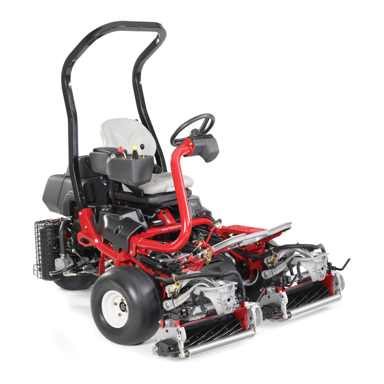
- Page 1 Form No. 3422-464 Rev B Greensmaster ® 3320 TriFlex ® Traction Unit Model No. 04530—Serial No. 403144001 and Up *3422-464* B Register at www.Toro.com. Original Instructions (EN)
- Page 2 This product complies with all relevant European Whenever you need service, genuine Toro parts, or directives; for details, please see the separate product additional information, contact an authorized Toro specific Declaration of Conformity (DOC) sheet. distributor and have the model and serial numbers of your product ready.
-
Page 3: Table Of Contents
Contents Electrical System Maintenance ......38 Electrical System Safety ........38 Servicing the Battery......... 38 Safety ............... 4 Locating the Fuses ........... 39 General Safety ........... 4 Jump-Starting the Machine....... 39 Safety and Instructional Decals ......5 Drive System Maintenance ........40 Setup .............. -
Page 4: Safety
Safety This machine has been designed in accordance with EN ISO 5395 and ANSI B71.4-2017 and meets these standards when you complete the setup procedures. General Safety This product is capable of amputating hands and feet and of throwing objects. Using this product for purposes other than its intended use could prove dangerous to you and bystanders. -
Page 5: Safety And Instructional Decals
Safety and Instructional Decals Safety decals and instructions are easily visible to the operator and are located near any area of potential danger. Replace any decal that is damaged or missing. decal115-8155 decal115-8203 115-8155 115-8203 1. Warning—read the Operator's Manual, do not prime or use 1. - Page 6 decal133-8062 133-8062 decal119-9346 119-9346 1. Press the pedal to unlock. 2. Read the Operator's Manual for more information. decal138-9695 138-9695 1. Engine speed—Fast 7. Reel speed—Neutral 2. Engine speed—Slow 8. Reel—Transport 3. Lower and engage the reels. 9. Reel—Mow 4. Raise and disengage the reels. 10.
- Page 7 decal132-9550 132-9550 1. Choke 3. Engine—run 2. Engine—start 4. Engine—stop decalbatterysymbols Battery Symbols Some or all of these symbols are on your battery. 1. Explosion hazard 6. Keep bystanders a safe distance away from the battery. 2. No fire, open flame, or 7.
- Page 8 decal131-2046 131-2046 1. Double lights 3. Off 2. Single light decal136-8505 136-8505 Replaces Decal 136-8506 for CE Machines Note: This machine complies with the industry standard stability test in the static lateral and longitudinal tests with the maximum recommended slope indicated on the decal. Review the instructions for operating the machine on slopes in the Operator’s Manual as well as the conditions in which you would operate the machine to determine whether you can operate the machine in the...
- Page 9 decal115-8156 115-8156 1. Reel height 3. 8–blade cutting unit 5. 14–blade cutting unit 7. Fast 2. 5–blade cutting unit 4. 11–blade cutting unit 6. Reel speed 8. Slow decal119-9345 119-9345...
-
Page 10: Setup
Series Traction Unit (Part No. 119-1691 Install the optional oil cooler. [purchased separately]) Grass-basket hook Install the grass-basket hooks. Flange bolts Gauge bar Cutting unit (obtain from your authorized Toro distributor) Install the cutting units and counter Grass basket weights. Electric-reel-motor counterweight Capscrew O-ring –... -
Page 11: Installing The Roll Bar
Torque the fasteners to 136 to 149 N∙m (100 to 110 ft-lb). Use the 3 bolts that you previously removed to secure the right side cover to the machine. Installing the Roll Bar Parts needed for this procedure: Roll bar Installing the Seat Bolt (1/2 x 3-3/4 inches) Flange nut (1/2 inch) -
Page 12: Installing The Steering Wheel
Locate the open connector on the main wire harness to the right of the seat and connect it to the wire harness that came with the seat. Route the seat wire harness around the seat Activating and Charging slides, ensuring that it is not pinched when you move the seat, and connect it to the port on the the Battery bottom of the seat. -
Page 13: Installing The Oil Cooler
secure them with the bolts and nuts (Figure Slide the rubber boot over the positive terminal to prevent a possible short from occurring. WARNING Incorrect battery cable routing could damage the tractor and cables, causing sparks. Sparks can cause the battery gasses to explode, resulting in personal injury. -
Page 14: Installing The Grass-Basket Hooks
Installing the Grass-Basket Installing the Cutting Units Hooks Parts needed for this procedure: Gauge bar Parts needed for this procedure: Cutting unit (obtain from your authorized Toro Grass-basket hook distributor) Flange bolts Grass basket Electric-reel-motor counterweight Procedure Capscrew O-ring Install the 6 grass-basket hooks onto the ends of the... -
Page 15: Setting The Clip-Control Feature
• Apply the CE warning decal (Part No. 136-8505) over the existing warning decal (Part No. 136-8506). • Apply the CE mark decal to the frame under the Setting the Clip-Control front of the seat (Figure 11). Feature No Parts Required Procedure The machine has a clip-control feature that varies the speed of the reels with the speed of the machine to... -
Page 16: Burnishing The Brakes
Product Overview Burnishing the Brakes No Parts Required Procedure Burnish the brakes; refer to Adjusting the Brakes (page 42). g014674 Figure 13 1. Engine 5. Steering wheel 2. Roll bar 6. Traction pedal 3. Control panel 7. Footrest 4. Seat 8. - Page 17 Throttle Lever The throttle lever (Figure 16) allows you to control the speed of the engine. Move the throttle lever toward the F position to increases the engine speed; move it toward the S position to decrease the engine speed. Note: You cannot shut off the engine using the throttle lever.
-
Page 18: Infocenter Control
Functional Control Lever InfoCenter Control The functional control lever (Figure 16) provides 2 Using the InfoCenter LCD Display traction selections plus a N position. You can EUTRAL shift from mow to transport or transport to mow (not The InfoCenter LCD display shows information about to neutral) while the machine is in motion;... - Page 19 Refer to the Service Controls the units used on the NITS Manual or your Authorized InfoCenter. The menu choices Toro Distributor for more are English or metric. information on the F AULTS Controls the language used ANGUAGE menu and the information on the InfoCenter.
- Page 20 Allows the distributor/engineer 0.150 ROTECTED ENUS to access protected menus by 0.200 inputting a passcode. 0.250 Controls the protected menus. ROTECTION ETTINGS 0.300 Resets the InfoCenter to ESET EFAULTS default settings. 0.375 Controls the raise delay time AISE ELAY 0.475 for the center cutting unit.
- Page 21 Faults menu that you or your distributor can use to manually as follows: identify the problem. Select the height-of-cut at which the cutting units For a list of faults, refer to your Authorized Toro are set. Distributor or the Service Manual. Choose the desired ground speed best suited for conditions.
-
Page 22: Specifications
Fuel-Shutoff Valve Cutting Unit Power Disconnect Connectors Close the fuel-shutoff valve (Figure 22), behind the seat and under the fuel tank, when storing or Before installing, removing, or working on the cutting transporting the machine on a truck or trailer. units, disconnect the cutting units from the power supply by separating the cutting unit power disconnect connectors... -
Page 23: Attachments/Accessories
Before Operation approved attachments and accessories. To ensure optimum performance and continued safety certification of the machine, use only genuine Toro Before Operation Safety replacement parts and accessories. Replacement parts and accessories made by other manufacturers... -
Page 24: Fuel Specification
Fuel Specification Filling the Fuel Tank Clean around the fuel-tank cap and remove it Fuel tank capacity: 26.6 L (7 US gallons) (Figure 24 Figure 25). Recommended Fuel: Unleaded gasoline with an octane rating of 87 or higher ((R+M)/2 rating method) Ethanol: Gasoline with up to 10% ethanol (gasohol) or 15% MTBE (methyl tertiary butyl ether) by volume is acceptable. -
Page 25: Performing Daily Maintenance
During Operation Important: Do not fill the fuel tank completely full. Install the cap. During Operation Safety Note: You will hear a click sound when the cap is secure. General Safety Wipe up any spilled fuel. • The owner/operator can prevent and is responsible for accidents that may cause personal injury or property damage. -
Page 26: Breaking In The Machine
– Park the machine on level ground. to the drive wheels may result in sliding and a loss of braking and steering. – Disengage the power take-off and lower the – Use extreme caution when operating attachments. the machine near drop-offs, ditches, –... -
Page 27: Checking The Machine After Starting The Engine
If fluid leaks continue to appear, contact Perform the following system checks daily to ensure that the interlock system is operating correctly: your authorized Toro distributor for assistance and, if necessary, replacement parts. Sit on the seat, move the traction pedal to the... -
Page 28: Driving The Machine Without Mowing
Driving the Machine without Move the functional-control lever to the M position or the T position and try to RANSPORT Mowing start the engine. The engine should not turnover or start, which • Ensure that the cutting units are fully raised. indicates that the interlock system is operating •... - Page 29 gaining the required timing necessary to minimize the cleanup mowing operation. Note: The delay in raising and lowering the center cutting unit depends on hydraulic fluid temperature. Cold hydraulic fluid results in a longer delay. As the fluid temperature increases, the delay time becomes shorter.
-
Page 30: After Operation
Cutting the Periphery and After Operation Finishing the Job Finish cutting the green by mowing the outer After Operation Safety periphery. Change the direction of cutting from the previous mowing. General Safety Note: Use the throttle lever to adjust the machine speed when you cut the periphery. -
Page 31: Inspecting And Cleaning After Mowing
Inspecting and Cleaning Towing the Machine after Mowing In case of an emergency, you can tow the machine for up to 0.4 km (1/4 mile). After mowing, thoroughly wash the machine with a Important: Do not tow the machine faster than 3 garden hose without a nozzle so that excessive water to 5 km/h (2 to 3 mph) to avoid damaging the drive pressure does not contaminate and damage the seals... -
Page 32: Maintenance
Carefully release pressure from components with stored energy. • To ensure safe, optimal performance of the machine, use only genuine Toro replacement parts. Replacement parts made by other manufacturers could be dangerous, and such use could void the product warranty. -
Page 33: Recommended Maintenance Schedule(S)
Recommended Maintenance Schedule(s) Maintenance Service Maintenance Procedure Interval • Torque the wheel nuts. After the first hour • Torque the wheel nuts. After the first 10 hours • Change the engine oil and filter. After the first 25 hours • Change the hydraulic-fluid filter. After the first 50 hours •... -
Page 34: Daily Maintenance Checklist
Daily Maintenance Checklist Duplicate this page for routine use. Maintenance Check Item For the week of: Mon. Tues. Wed. Thurs. Fri. Sat. Sun. Check the safety-interlock operation. Check the instrument operation Check the leak-detector alarm. Check the brake operation. Check the fuel level. Check the hydraulic-fluid level. -
Page 35: Lubrication
Lubrication Engine Maintenance Greasing the Machine Engine Safety • Shut off the engine before checking the oil or Service Interval: Every 400 hours adding oil to the crankcase. Lubricate the grease fitting with No. 2 lithium grease. • Do not change the governor speed or overspeed Wipe the grease fitting clean so that you do not the engine. -
Page 36: Servicing The Engine Oil
g005111 Figure 33 1. Dipstick 2. Filler cap g005126 Figure 32 1. Foam element 2. Paper element Unscrew the dipstick, pull it out of the tube, and check the oil level. Check the condition of the paper element. Clean If the oil level is low, remove the filler cap from it by gently tapping it on a flat surface or replace the valve cover and add oil into the engine it if needed. -
Page 37: Replacing The Spark Plugs
Fuel System Clean the threads of the drain plug, apply PTFE sealant, and install the drain plug (Figure 34). Maintenance Remove the oil filter (Figure 34). Apply a light coat of clean oil to the new filter gasket. Replacing the Fuel Filter Screw the filter on by hand until the gasket Service Interval: Every 800 hours (sooner if the fuel contacts the filter adapter, then tighten it 3/4 to 1... -
Page 38: Electrical System Maintenance
Electrical System WARNING Incorrect battery cable routing could damage Maintenance the tractor and cables, causing sparks. Sparks can cause the battery gasses to Electrical System Safety explode, resulting in personal injury. • Always disconnect the negative (black) • Disconnect the battery before repairing the battery cable before disconnecting the machine. -
Page 39: Locating The Fuses
Locating the Fuses Jump-Starting the Machine The fuses in the electrical system are located under If you need to jump start the machine, you can use the the seat (Figure 37). alternate-positive post (located on the starter solenoid) instead of the positive battery post (Figure 39). -
Page 40: Drive System Maintenance
If the wheel still turns when the Wheel nut torque specification: 95 to 122 N∙m (70 eccentric is at the maximum adjustment, to 90 ft-lb) contact your authorized Toro distributor Note: To ensure even distribution, torque the wheel or refer to the Service Manual for further nuts in a X pattern. -
Page 41: Adjusting The Mowing Speed
Adjusting the Mowing Speed The mow speed is set to 3.8 mph at the factory. You can adjust the forward moving speed from 0 to 8 km/h (0 to 5 mph). Loosen the jam nut on the trunnion bolt (Figure 42). -
Page 42: Brake Maintenance
5-gallon pails or 55-gallon drums. See the Parts Catalog or your authorized Toro distributor for part numbers.) Alternate fluids: If the Toro fluid is not available, other fluids may be used provided they meet all the following material properties and industry specifications. The use of synthetic fluid is not recommended. - Page 43 Mobil EAL EnviroSyn 46H is the only synthetic biodegradable fluid approved by Toro. This fluid is compatible with the elastomers used in Toro hydraulic systems and is suitable for a wide-range of temperature conditions. This fluid is compatible with conventional mineral oils, but for...
- Page 44 Every 800 hours Hydraulic Fluid Capacity: 25.7 L (6.8 US gallons) If the fluid becomes contaminated, have your authorized Toro distributor flush the system. Contaminated fluid looks milky or black when compared to clean fluid. Clean the area around the filter mounting area (Figure 45).
-
Page 45: Checking The Hydraulic Lines And Hoses
Checking the Hydraulic Lines and Hoses WARNING Hydraulic fluid escaping under pressure can penetrate skin and cause injury. • Get immediate medical help if fluid is injected into skin. • Ensure that all hydraulic fluid hoses and lines are in good condition and all hydraulic connections and fittings are tight before applying pressure to the hydraulic g229108... - Page 46 g229110 Figure 48 Leak Alert! g229112 1. Float switch 3. Fluid level (warm) Figure 49 (down—closed) Fluid level down 118 1. Clean rod or screwdriver 3. Press down on the float to 177 ml (4 to 6 oz) switch 2. Warning buzzer 2.
-
Page 47: Cutting Unit Maintenance
Installing the Electrical Cutting Unit Maintenance Counterweights Blade Safety Secure the electrical counterweight to the existing counterweight with 2 capscrews as shown in Figure Refer to and complete the procedure in Maintenance Safety (page 32). A worn or damaged blade or bedknife can break, and a piece could be thrown toward you or bystanders, resulting in serious personal injury or death. - Page 48 Close the latches down and around the cutting-unit bar and lock them in place (Figure 53). Note: You can hear a click and feel when the latches are properly locked in place. Coat the spline shaft of the cutting unit motor with clean grease (Figure 55).
-
Page 49: Checking The Reel-To-Bedknife Contact
Removing the Cutting Units Disconnect the cutting unit power disconnect couplers; refer to Cutting Unit Power Disconnect Connectors (page 22). CAUTION If you do not disconnect the power to the cutting units, someone could g036124 Figure 57 accidentally start the cutting unit, causing serious injury to hands and feet. -
Page 50: Backlapping The Reels
Backlapping the Reels Wash all lapping compound off of the cutting units. Adjust the cutting unit reel to bedknife as needed. Move the cutting-unit reel speed control WARNING to the desired mowing position. Contact with the reels or other moving parts can result in personal injury. -
Page 51: Storage
Storage If you wish to store the machine for a long period of time, the perform following steps: Always shut off the engine, remove the key (if equipped), wait for all moving parts to stop, and allow the machine to cool before adjusting, cleaning, storing, or repairing the machine. - Page 52 Notes:...
- Page 53 Notes:...
- Page 54 The Way Toro Uses Information Toro may use your personal information to process warranty claims, to contact you in the event of a product recall and for any other purpose which we tell you about. Toro may share your information with Toro's affiliates, dealers or other business partners in connection with any of these activities. We will not sell your personal information to any other company.
- Page 55 While the exposure from Toro products may be negligible or well within the “no significant risk” range, out of an abundance of caution, Toro has elected to provide the Prop 65 warnings. Moreover, if Toro does not provide these warnings, it could be sued by the State of California or by private parties seeking to enforce Prop 65 and subject to substantial penalties.
- Page 56 Countries Other than the United States or Canada Customers who have purchased Toro products exported from the United States or Canada should contact their Toro Distributor (Dealer) to obtain guarantee policies for your country, province, or state. If for any reason you are dissatisfied with your Distributor's service or have difficulty obtaining guarantee information, contact the Toro importer.