Table of Contents
Advertisement
ZS-RS70BT/RS70BTB
SERVICE MANUAL
Ver. 1.0 2013.08
CD player section
System
Compact disc digital audio system
Laser diode properties
Emission duration: Continuous
Laser output: Less than 44.6 μW
(This output is the value measurement at a
distance of 200 mm from the objective lens
surface on the optical pick-up block with 7 mm
aperture.)
Number of channels
2
Frequency response
20 Hz
20,000 Hz +1/–2 dB
Wow and flutter
Below measurable limit
Bluetooth section
Communication System
Bluetooth Specification Version 3.0
Output
Bluetooth Specification Power Class 2
Maximum communication range
1
Line of sight approx. 10 m*
Frequency band
2.4 GHz band (2.4000 GHz
2.4835 GHz)
Modulation method
FHSS
2
Supported Bluetooth Profiles*
A2DP (Advanced Audio Distribution Profile)
3
AVRCP*
(Audio/Video Remote Control Profile)
4
Supported codec*
SBC (Subband Codec)
1
*
The actual range will vary depending on factors
such as obstacles between devices, magnetic
fields around a microwave oven, static
electricity, reception sensitivity, aerial
performance, operating system, application
software, etc.
2
*
Blue tooth standard profiles provide the
specifications for Bluetooth communication
between devices.
*
3
Some oper ations may not be available
depending on the device.
4
*
Codec: Audio signal compression and
conversion format
Radio section (RS70BT)
Frequency range
Uruguay, Paraguay, Peru, Chile and Bolivia
models
FM: 87.5 MHz
108 MHz (100 kHz step)
87.5 MHz
108 MHz (50 kHz step)
AM: 530 kHz
1,610 kHz (10 kHz step)
531 kHz
1,602 kHz (9 kHz step)
Latin American models except for Uruguay,
Paraguay, Peru, Chile, Bolivia and Brazil models
FM: 87.5 MHz
108 MHz (100 kHz step)
AM: 530 kHz
1,710 kHz (10 kHz step)
9-893-795-01
Sony Corporation
2013H33-1
©
2013.08
Published by Sony Techno Create Corporation
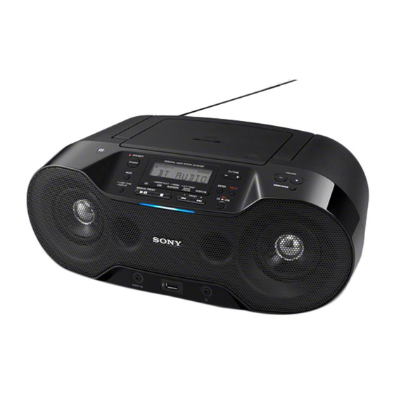
Photo: ZS-RS70BT
SPECIFICATIONS
Intermediate frequency
FM: 128 kHz
AM: 45 kHz
Antennas
FM: Telescopic antenna
AM: Built-in ferrite bar antenna
Radio section (RS70BTB)
Frequency range
DAB (Band-III): 174.928 MHz
239.200 MHz
FM: 87.5 MHz
108 MHz (50 kHz step)
Intermediate frequency
DAB (Band-III): 2.048 MHz
FM: 2.198 MHz
DAB (Band-III) frequency table (MHz)
Channel
Frequency
Channel
Frequency
5A
174.928
10N
210.096
5B
176.640
10B
211.648
5C
178.352
10C
213.360
5D
180.064
10D
215.072
6A
181.936
11A
216.928
6B
183.648
11N
217.088
6C
185.360
11B
218.640
6D
187.072
11C
220.352
7A
188.928
11D
222.064
7B
190.640
12A
223.936
7C
192.352
12N
224.096
7D
194.064
12B
225.648
8A
195.936
12C
227.360
8B
197.648
12D
229.072
8C
199.360
13A
230.784
8D
201.072
13B
232.496
9A
202.928
13C
234.208
9B
204.640
13D
235.776
9C
206.352
13E
237.488
9D
208.064
13F
239.200
10A
209.936
Antenna
Telescopic antenna
Input
AUDIO IN
Stereo mini jack
(USB) port
Type A, maximum current 500 mA, USB 2.0 Full
Speed compatible
Output
(headphones) stereo mini jack
For 16
32
impedance headphones
Model Name Using Similar Optical Pick-up Block
Optical Pick-up Block Name
Supported audio formats
Supported bit rates
MP3 (MPEG 1 Audio Layer-3):
32 kbps
320 kbps, VBR
WMA:
48 kbps
192 kbps, VBR
Sampling frequencies
MP3 (MPEG 1 Audio Layer-3):
32/44.1/48 kHz
WMA:
32/44.1/48 kHz
General (RS70BT)
Speaker
Full range, 8 cm dia., 3.2 , cone type (2)
Power output
2.3 W + 2.3 W (at 3.2 , 10% harmonic
distortion)
Power requirements
Uruguay, Paraguay, Peru, Chile and
Bolivia models
230 V AC, 50 Hz (AC power supply)
9 V DC (6 R14 (size C) batteries)
Latin American models except for Uruguay,
Paraguay, Peru, Chile, Bolivia and Brazil models
120 V AC, 60 Hz (AC power supply)
9 V DC (6 R14 (size C) batteries)
Power consumption
AC 16 W
1,
2
Battery Life*
*
Playback of CD
Approx. 7.5 hours
Playback of USB device
Approx. 7 hours (at 100 mA load)
Approx. 3.5 hours (at 500 mA load)
FM reception
Approx. 19 hours
Bluetooth
Approx. 10 hours
*
1
Measur ed by Sony standards. The actual
battery life may vary depending on the
circumstances of the unit or operating
conditions.
*
2
When using Sony alkaline batteries
Dimensions
Approx. 380 mm × 158 mm × 235 mm (W/H/D)
(incl. projecting parts)
Mass
Approx. 3.3 kg (incl. batteries)
PERSONAL AUDIO SYSTEM
AEP Model
UK Model
ZS-RS70BTB
E Model
ZS-RS70BT
NEW
EM101 RNSZS
General (RS70BTB)
Speaker
Full range, 8 cm dia., 3.2 , cone type (2)
Power output
2.3 W + 2.3 W (at 3.2 , 10% harmonic
distortion)
Power requirements
230 V AC, 50 Hz (AC power supply)
9 V DC (6 R14 (size C) batteries)
Power consumption
AC 16 W
1,
2
Battery Life*
*
Playback of CD
Approx. 7.5 hours
Playback of USB device
Approx. 7 hours (at 100 mA load)
Approx. 3.5 hours (at 500 mA load)
DAB reception
Approx. 9 hours
FM reception
Approx. 9 hours
Bluetooth
Approx. 10 hours
1
*
Measur ed by Sony standards. The actual
battery life may vary depending on the
circumstances of the unit or operating
conditions.
2
*
When using Sony alkaline batteries
Dimensions
Approx. 380 mm × 158 mm × 235 mm (W/H/D)
(incl. projecting parts)
Mass
Approx. 3.3 kg (incl. batteries)
Supplied accessories
AC power cord (1)
Protecting sheet (1)
Design and specifications are subject to change
without notice.
Advertisement
Table of Contents

Related Manuals for Sony ZS-RS70BT


Summary of Contents for Sony ZS-RS70BT
- Page 1 9 V DC (6 R14 (size C) batteries) Approx. 10 hours Line of sight approx. 10 m* 183.648 217.088 Measur ed by Sony standards. The actual Latin American models except for Uruguay, Frequency band battery life may vary depending on the 185.360 218.640...
- Page 2 COMPONENTS IDENTIFIED BY MARK 0 OR DOTTED LINE WITH MARK 0 ON THE SCHEMATIC DIAGRAMS AND IN THE PARTS LIST ARE CRITICAL TO SAFE OPERATION. REPLACE THESE COMPONENTS WITH SONY PARTS WHOSE PART NUMBERS APPEAR AS SHOWN IN THIS MANUAL OR IN SUPPLEMENTS PUBLISHED BY SONY.
-
Page 3: Table Of Contents
ZS-RS70BT/RS70BTB TABLE OF CONTENTS SERVICING NOTES 5-11. Schematic Diagram ..........- MAIN Section (1/3) (RS70BT) - ........37 5-12. Schematic Diagram DISASSEMBLY - MAIN Section (2/3) (RS70BT) - ........38 2-1. Disassembly Flow ............5-13. Schematic Diagram 2-2. Cabinet (Upper) Block ............ -
Page 4: Servicing Notes
ZS-RS70BT/RS70BTB SECTION 1 SERVICING NOTES NOTES ON HANDLING THE OPTICAL PICK-UP CHUCK PLATE JIG ON REPAIRING BLOCK OR BASE UNIT On repairing CD section, playing a disc without the CD lid, use The laser diode in the optical pick-up block may suffer electro- CHUCK PLATE JIG. - Page 5 ZS-RS70BT/RS70BTB MODEL IDENTIFICATION Connecting method Distinguish the destination by referring to the model number label. Procedure: 1. Turn on the NFC function of the smartphone. Model number label Part No. 2. If the smartphone OS is Android 2.3.3 or later, but earlier than Android 4.1, start the app “NFC Easy Connect”...
-
Page 6: Disassembly
ZS-RS70BT/RS70BTB SECTION 2 DISASSEMBLY • This set can be disassembled in the order shown below. 2-1. DISASSEMBLY FLOW 2-2. CABINET (UPPER) BLOCK (Page 7) 2-3. CABINET (FRONT) BLOCK-1 2-5. SPRING (CD) 2-6. CD BLOCK ASSY (Page 8) (Page 10) (Page 11) 2-4. -
Page 7: Cabinet (Upper) Block
ZS-RS70BT/RS70BTB Note: Follow the disassembly procedure in the numerical order given. 2-2. CABINET (UPPER) BLOCK 2 Lift up the telescopic antenna. 5 Open the CD lid. 1 Lift up the hundle. 3 five tapping screws (BV B2.6) 6 three tapping screws (BV B2.6) -
Page 8: Cabinet (Front) Block-1
ZS-RS70BT/RS70BTB 2-3. CABINET (FRONT) BLOCK-1 3 flexible flat cable (8 core) (CN804) 2 flexible flat cable (11P) (CN801) 6 connector (CN301) 1 flexible flat cable (14 core) 5 connector (CN807) (CN902) 4 connector – – (CN303) Note: When installing the flexible flat –... -
Page 9: Cabinet (Front) Block-2
ZS-RS70BT/RS70BTB 2-4. CABINET (FRONT) BLOCK-2 3 cabinet (front) block – Rear view – 1 battery lid 2 four tapping screws (BV B2.6) 2 tapping screw 2 tapping screw (BV B2.6) (BV B2.6) 2 three tapping screws (BV B2.6) – Rear view –... -
Page 10: Spring (Cd)
ZS-RS70BT/RS70BTB 2-5. SPRING (CD) 1 Open the CD lid. 4 CD lid assy CD lid spring (CD) 6 spring (CD) CD lid 3 shaft ditch 4 shaft 2 Remove the spring 3 shaft (CD) from the ditch of CD lid. -
Page 11: Cd Block Assy
ZS-RS70BT/RS70BTB 2-6. CD BLOCK ASSY 1 two tapping screw (PWH B2.6) 1 two tapping screw (PWH B2.6) 2 CD block assy – Cabinet (upper) block bottom view – 2-7. CD BOARD Note 1: Before disconnecting the flexible flat cable (16 core) of optical pick-up block, solder the short-land. -
Page 12: Optical Pick-Up (Em101 Rnszs) (Op1)
ZS-RS70BT/RS70BTB 2-8. OPTICAL PICK-UP (EM101 RNSZS) (OP1) 4 CD cover 3 claw Note: Four claws might be Upper side optical pick-up fixed by bond.When installing the CD cover, please fix four claws using the bond. Lower side vibration proof rubber... -
Page 13: Jack Board
ZS-RS70BT/RS70BTB 2-10. JACK BOARD 3 connector (CN305) 2 ferrite core with wire 1 tapping screw (PWH B2.6) 5 HOLD JACK board 6 JACK board – inet – 4 tapping screw 5 HOLD JACK board (BV B2.6) 4 tapping screw 4 tapping screw (BV B2.6) -
Page 14: Bluetooth Module (Bt1)
ZS-RS70BT/RS70BTB 2-11. BLUETOOTH MODULE (BT1) Note 1: When Bluetooth module is replaced, refer to “NOTE OF REPLACING THE Bluetooth MODULE OR RC-S711 (NFC)” on page 5. 3 Remove the SOFT board block in the direction of an arrow. Note 2: When installing the flexible flat 5 SOFT board block cable, ensure the colored line. -
Page 15: Loudspeaker (7.7 Cm) (L/R-Ch) (Sp101, Sp201)
ZS-RS70BT/RS70BTB 2-12. LOUDSPEAKER (7.7 cm) (L/R-CH) (SP101, SP201) Loudspeaker (7.7 cm) (R-ch) (SP201) setting Install the loudspeaker (7.7 cm) (R-ch) (SP201) in inside two ribs. 3 loudspeaker (7.7 cm) 2 three tapping screws (R-ch) (SP201) (BV B2.6) 1 Remove solder 3 loudspeaker (7.7 cm) -
Page 16: Tuner Board (Rs70Bt)/Dab Board (Rs70Btb)
ZS-RS70BT/RS70BTB 2-13. TUNER BOARD (RS70BT)/DAB BOARD (RS70BTB) 2 telescopic antenna (ANT1) flexible flat cable (11P) holder (PWB, TU) 1 screw (P M3) tape (sub material) TUNER board (RS70BT)/ DAB board (RS70BTB) 3 connector (CN903) – – 4 connector (CN808) tape (sub material) tape (sub material) 6 Remove the speaker TUNER/DAB board block in the direction of an arrow. -
Page 17: Main Board
ZS-RS70BT/RS70BTB 2-14. MAIN BOARD 5 tapping screw (BV B2.6) 5 tapping screw (BV B2.6) 5 two tapping screws (BV B2.6) 6 MAIN board Note: When installing the flexible flat cable, ensure the colored line. No slanting after insertion. 1 connector Insert is straight to the interior. -
Page 18: Fuse (F982), Power Board Block
ZS-RS70BT/RS70BTB 2-15. FUSE (F982), POWER BOARD BLOCK 5 two tapping screws (BV B2.6) 5 two tapping screws (BV B2.6) 6 POWER board block 5 two tapping screws (BV B2.6) 1 fuse (F982) 4 connector (CN982) 5 two tapping screws (BV B2.6) -
Page 19: Power Board, Fuse (F983)
ZS-RS70BT/RS70BTB 2-16. POWER BOARD, FUSE (F983) 2 power transformer block 1 Remove five solders. 3 fuse (F983) 4 POWER board... -
Page 20: Test Mode
ZS-RS70BT/RS70BTB SECTION 3 TEST MODE COLD RESET 4. Press the [ PAIRING BLUETOOTH] button, and the Blue- System μ-com is reset and EEPROM is cleared. tooth module fi rmware version is displayed. Note: The informations of Bluetooth and DAB are not initialized. - Page 21 ZS-RS70BT/RS70BTB AM TUNER STEP CHANGE DAB MANUAL MODE (AEP and UK models only) (Bolivian, Chilean, Paraguayan, Peruvian and Uruguay- Receiving mode can be changed to normal (Alphabetical) mode an models only) or manual mode. The AM tuning interval can be changed over 9 kHz or 10 kHz.
- Page 22 ZS-RS70BT/RS70BTB Bluetooth INFORMATION INITIALIZE ERP TEST (AEP and UK models only) Bluetooth information is initialized. The ERP audio signal detection check. Confi rm ERP test with reference to the following fl ow. Procedure: 1. Press the [POWER] (Except AEP and UK models)/[OPER- Procedure: ATE] (AEP and UK models) button to turn the power on.
- Page 23 ZS-RS70BT/RS70BTB CD ADJUSTMENT MONITOR MODE CD FACTORY MODE It can check the data of the result after automatic adjustment. Note 1: Do not enter the this mode while any other test mode is in prog- ress. Note 2: Do not enter any other test mode while the this mode is in prog- Procedure: ress.
- Page 24 ZS-RS70BT/RS70BTB CD SERVICE MODE [CD], [ MEMORY SELECT USB] (CD playing states): Use these keys to FE disturbance level setting. When [CD] is This mode can move the SLED of the optical pick-up, and also can pressed, the FE disturbance level is up. When [MEMORY SE- turn the optical pick-up laser power on and off.
-
Page 25: Electrical Checks
ZS-RS70BT/RS70BTB SECTION 4 ELECTRICAL CHECKS Connection Location: no mark: E41 model TUNER SECTION 0 dB = 1 V CD SECTION ): E92 and MX models – CD Board (Conductor Side) – AM FREQUENCY COVERAGE CHECK [AM] (RS70BT only) Note: 1. CD block is basically constructed to operate without adjustment. -
Page 26: Diagrams
ZS-RS70BT/RS70BTB SECTION 5 DIAGRAMS 5-1. BLOCK DIAGRAM - CD/USB Section - OPTICAL PICK-UP BLOCK (EM101 RNSZS) CD L (Page 27) 5 A IN RFOUT 1 EFMIN LCHO 7 B IN 17 TEIN RCHO R-CH 6 C IN 8 D IN... -
Page 27: Block Diagram - Main Section
ZS-RS70BT/RS70BTB 5-2. BLOCK DIAGRAM - MAIN Section - INPUT SELECTOR, ELECTRICAL VOLUME IC302 (Page 26) R-CH CD L 1 IV L CD J301 POWER AMP ICOUT L 13 R2 VOLIN L L OUT IC304 (RS70BT) J351 R-CH 5 IN L AU... -
Page 28: Block Diagram - Panel/Power Supply Section
ZS-RS70BT/RS70BTB 5-3. BLOCK DIAGRAM - PANEL/POWER SUPPLY Section - POWER AMP VCC SYSTEM CONTROLLER LIQUID CRYSTAL IC801 (3/3) DISPLAY DRIVER IC601 +3.3V CD +3.3V REGULATOR SEG0 – DATA 47 O-LCD-DATA LCD601 Q905 SEG31 LIQUID 48 O-LCD-WR I-REG3.3V-CHK CRYSTAL 49 O-LCD-CS COM1 –... - Page 29 ZS-RS70BT/RS70BTB THIS NOTE IS COMMON FOR PRINTED WIRING BOARDS AND SCHEMATIC DIAGRAMS. • Circuit Boards Location (In addition to this, the necessary note is printed in each block.) For Printed Wiring Boards. For Schematic Diagrams. TUNER board (RS70BT)/ DAB board (RS70BTB)
-
Page 30: Printed Wiring Board - Cd Board
ZS-RS70BT/RS70BTB 5-4. PRINTED WIRING BOARD - CD Board - • See page 29 for Circuit Boards Location. • : Uses unleaded solder. CD BOARD CD BOARD (COMPONENT SIDE) (CONDUCTOR SIDE) R503 C507 C504 C505 R505 IC703 OPTICAL PICK-UP BLOCK (1/2) -
Page 31: Schematic Diagram - Cd Board
ZS-RS70BT/RS70BTB 5-5. SCHEMATIC DIAGRAM - CD Board - • See page 50 for Waveforms. • See page 50 for IC Block Diagrams. • See page 54 for IC Pin Function Description. CD BOARD CN702 R518 C519 4700p TP701 TP702 R514... -
Page 32: Printed Wiring Board - Tuner Board (Rs70Bt)
ZS-RS70BT/RS70BTB 5-6. PRINTED WIRING BOARD - TUNER Board (RS70BT) - • See page 29 for Circuit Boards Location. • : Uses unleaded solder. TUNER BOARD IC905 C913 C914 JW12 (Page 36) MAIN BOARD CN903 ANT1 FM TELESCOPIC ANTENNA FFC3 FM test point... -
Page 33: Schematic Diagram - Tuner Board (Rs70Bt)
ZS-RS70BT/RS70BTB 5-7. SCHEMATIC DIAGRAM - TUNER Board (RS70BT) - • See page 50 for Waveforms. • See page 50 for IC Block Diagrams ANT1 FM TELESCOPIC ANTENNA TUNER BOARD 33nH 1000p 0.47 10uH BAV99 BAV99 BAV99 IC B/D L908 FM test... -
Page 34: Printed Wiring Board - Dab Board (Rs70Btb)
ZS-RS70BT/RS70BTB 5-8. PRINTED WIRING BOARD - DAB Board (RS70BTB) - • See page 29 for Circuit Boards Location. • : Uses unleaded solder. DAB BOARD IC371 C273 R276 R275 ANT1 FM TELESCOPIC R176 R175 ANTENNA JW910 JW911 C173 R173 JW909... -
Page 35: Schematic Diagram - Dab Board (Rs70Btb)
ZS-RS70BT/RS70BTB 5-9. SCHEMATIC DIAGRAM - DAB Board (RS70BTB) - • See page 50 for IC Block Diagrams. DAB BOARD (Page 42) ANT1 FM TELESCOPIC ANTENNA MAIN BOARD (2/3) CN903 BAV99 DAB1 C273 DAB MODULE 470p (DAB TUNER) R275 R276 4.7k... -
Page 36: Printed Wiring Boards - Main Section (Rs70Bt)
ZS-RS70BT/RS70BTB 5-10. PRINTED WIRING BOARDS - MAIN Section (RS70BT) - • See page 29 for Circuit Boards Location. • : Uses unleaded solder. SOFT BOARD MAIN BOARD (SIDE A) CN810 (NC) CN801 C855 FFC6 (E92, MX) (E41) (Page 46) IC802... -
Page 37: Schematic Diagram - Main Section (1/3) (Rs70Bt)
ZS-RS70BT/RS70BTB 5-11. SCHEMATIC DIAGRAM - MAIN Section (1/3) (RS70BT) - • See page 50 for IC Block Diagrams. MAIN BOARD (1/3) CN303 TP101 (Page 45) L-CH R124 R127 TP201 JACK ALEV DET R-CH BOARD R224 R227 CN304 CD RCH D102... -
Page 38: Schematic Diagram - Main Section (2/3) (Rs70Bt)
ZS-RS70BT/RS70BTB 5-12. SCHEMATIC DIAGRAM - MAIN Section (2/3) (RS70BT) - • See page 50 for IC Block Diagrams. MAIN BOARD (2/3) (Page 37) MAIN BOARD (1/3) Q904 2SD2394-F +6V REGULATOR 11.1 TP905 Q902 L907 R904 R903 R902 R901 KTA1273-Y-AT 100uH 2.2k... -
Page 39: Schematic Diagram - Main Section (3/3) (Rs70Bt)
ZS-RS70BT/RS70BTB 5-13. SCHEMATIC DIAGRAM - MAIN Section (3/3) (RS70BT) - • See page 50 for Waveforms. • See page 54 for IC Pin Function Description. MAIN BOARD (3/3) (Page 38) MAIN BOARD (2/3) TP812 C862 R403 R405 R407 C872 C874... -
Page 40: Printed Wiring Boards - Main Section (Rs70Btb)
ZS-RS70BT/RS70BTB 5-14. PRINTED WIRING BOARDS - MAIN Section (RS70BTB) - • See page 29 for Circuit Boards Location. • : Uses unleaded solder. SOFT BOARD MAIN BOARD (SIDE A) CN810 (NC) CN801 FFC6 (Page 46) 1-888-989- (11) CN802 C893 C855... -
Page 41: Schematic Diagram - Main Section (1/3) (Rs70Btb)
ZS-RS70BT/RS70BTB 5-15. SCHEMATIC DIAGRAM - MAIN Section (1/3) (RS70BTB) - • See page 50 for IC Block Diagrams. MAIN BOARD (1/3) ALEV DET CN303 TP101 (Page 45) L-CH R124 R127 JACK AUDIO_IN_CHK TP201 R-CH BOARD R224 R227 CN304 CD RCH... -
Page 42: Schematic Diagram - Main Section (2/3) (Rs70Btb)
ZS-RS70BT/RS70BTB 5-16. SCHEMATIC DIAGRAM - MAIN Section (2/3) (RS70BTB) - • See page 50 for IC Block Diagrams. MAIN BOARD (2/3) (Page 41) MAIN BOARD (1/3) Q904 2SD2394-F +6V REGULATOR 11.1 TP905 Q902 L907 KTA1273-Y-AT R904 R903 R902 R901 100uH 2.2k... -
Page 43: Schematic Diagram - Main Section (3/3) (Rs70Btb)
ZS-RS70BT/RS70BTB 5-17. SCHEMATIC DIAGRAM - MAIN Section (3/3) (RS70BTB) - • See page 50 for Waveforms. • See page 54 for IC Pin Function Description. MAIN BOARD (3/3) (Page 42) MAIN BOARD (2/3) TP812 C862 R403 R405 R407 C872 C874... -
Page 44: Printed Wiring Board - Connector Board
ZS-RS70BT/RS70BTB 5-18. PRINTED WIRING BOARD - CONNECTOR Board - 5-20. PRINTED WIRING BOARDS - JACK/LED (NFC) Boards - • See page 29 for Circuit Boards Location. • : Uses unleaded solder. • See page 29 for Circuit Boards Location. •... -
Page 45: Schematic Diagram - Jack/Led (Nfc) Boards
ZS-RS70BT/RS70BTB 5-21. SCHEMATIC DIAGRAM - JACK/LED (NFC) Boards - (RS70BT) JACK BOARD LED (NFC) BOARD FB601 R670 (RS70BT) CN304 D602 MAIN 1L434FV22D0TDF01 BOARD FB151 (2/3) L-CH J351 CN902 FB602 R671 D603 AUDIO IN (Page 38) FB251 1L434FV22D0TDF01 R-CH D602 - 606... -
Page 46: Printed Wiring Boards - Key Section
ZS-RS70BT/RS70BTB 5-22. PRINTED WIRING BOARDS - KEY Section - • See page 29 for Circuit Boards Location. • : Uses unleaded solder. (RS70BT) (RS70BTB) MAIN BOARD MAIN BOARD RC-S711 CN801 CN801 (NFC) (Page 36) (Page 40) KEY A BOARD FFC6... -
Page 47: Schematic Diagram - Key Section
ZS-RS70BT/RS70BTB 5-23. SCHEMATIC DIAGRAM - KEY Section - • See page 50 for IC Block Diagrams. KEY A BOARD S608 R606 R607 R608 R609 R610 R611 2.2k 3.3k 6.8k AUTO RRESET RADIO FM/AM (RS70BT) S607 S609 S610 S611 S612 S613... -
Page 48: Printed Wiring Boards - Power Board
ZS-RS70BT/RS70BTB 5-24. PRINTED WIRING BOARDS - POWER Board - • See page 29 for Circuit Boards Location. • : Uses unleaded solder. (RS70BT) (RS70BTB) J981 J981 - AC IN - AC IN POWER BOARD POWER BOARD FH985 FH985 F983 F983... -
Page 49: Schematic Diagram - Power Board
ZS-RS70BT/RS70BTB 5-25. SCHEMATIC DIAGRAM - POWER Board - (RS70BT) POWER BOARD F983 CN982 T2.0AL 250V BAT+ BAT– J981 DRY BATTERY SIZE “C” - AC IN (IEC DESIGNATION R14) T981 6PCS. 9V POWER F982 JW984 TRANSFORMER T3.15AL 250V JW983 TOTAL CURRENT... - Page 50 ZS-RS70BT/RS70BTB • Waveforms • IC Block Diagrams – CD Board – – TUNER Board – – CD Board – IC701 LC786950T-US-H IC701 2 (RF OUT) IC1 3 (GP03/DCLK) (CD play mode) CLOCK EFMIN 1 C2F (LRSY) 1 Vp-p GENERATOR MP3/PCM OUTPUT CONTROL 30.8 s...
- Page 51 ZS-RS70BT/RS70BTB IC703 BA5826HFP-E2 IC704 NCP380HSNAJAAT1G VO1(–) BLOCKING D.BUFF CONTROL VO4(–) VO1(+) IN 1 D.BUFF LEVEL D.BUFF SHIFT VO4(+) D.BUFF LEVEL CURRENT ILIM SHIFT LIMITER GND 2 GATE DRIVER RESET IN4' THERMAL CONTROL LOGIC EN 3 FLAG /FLAG SHUT-DOWN BLOCK AND TIMER...
- Page 52 ZS-RS70BT/RS70BTB IC905 S-T111B33MC-OGSTFG VOUT ON/OFF OVER CURRENT PROTECTOR REFERENCE ON/OFF VOLTAGE CIRCUIT CIRCUIT – DAB Board – IC905 BD33HA3WEFJ-E2 IC906 BU12TD3WG-TR VIN 1 VREF VOUT OVER CURRENT PROTECT N.C. SOFT START DISCHARGE STBY STBY THERMAL SHUTDOWN – MAIN Board –...
- Page 53 ZS-RS70BT/RS70BTB IC401 BU4053BCF-E2 IC901 NJW4152GM1-A (TE2) PV+ 1 14 X PULSE BY PULSE BUFFER 12 X0 UVLO BINARY TO 1 OF 2 DECODER WITH INHIBIT FREQUENCY STANDBY INHIBIT REGULATOR CONTROL ON/OFF LEVEL CONVERTER ON/OFF ER.AMP SOFT START 10 B RT 4 IN–...
- Page 54 ZS-RS70BT/RS70BTB • IC Pin Function Description CD BOARD IC702 LC87F1JJ2AU-SQFP-H (USB CONTROLLER) Pin No. Pin Name Description Not used Reset signal input from the system controller “L”: reset Sub system clock input terminal Fixed at “H” in this unit Sub system clock output terminal...
- Page 55 ZS-RS70BT/RS70BTB MAIN BOARD IC801 LC87F7NJ2AVUEJ-2H (SYSTEM CONTROLLER) (RS70BT) Pin No. Pin Name Description O-USB RES Reset signal output to the USB controller “L”: reset M-MUTE Muting on/off control signal output to the coil/motor drive “L”: muting on O-CD DO Serial data output to the CD-MP3 processor...
- Page 56 ZS-RS70BT/RS70BTB Pin No. Pin Name Description 67 to 74 Not used O-BT RESET Reset signal output to the Bluetooth module “L”: reset I-BT-MUTE Muting on/off control signal input from the Bluetooth module “L”: muting on I-BT-RTS Request to send signal input from the Bluetooth module...
- Page 57 ZS-RS70BT/RS70BTB MAIN BOARD IC801 LC87F7NP6AVUEJ-2H (SYSTEM CONTROLLER) (RS70BTB) Pin No. Pin Name Description O-USB RES Reset signal output to the USB controller “L”: reset M-MUTE Muting on/off control signal output to the coil/motor drive “L”: muting on O-CD DO Serial data output to the CD-MP3 processor...
- Page 58 ZS-RS70BT/RS70BTB Pin No. Pin Name Description I-BT-MUTE Muting on/off control signal input from the Bluetooth module “L”: muting on I-BT-RTS Request to send signal input from the Bluetooth module O-BT-CTS Clear to send signal output to the Bluetooth module O-UART-SW Serial data selection signal output to the data selector “L”: DAB, “H”: Bluetooth...
-
Page 59: Exploded Views
ZS-RS70BT/RS70BTB SECTION 6 EXPLODED VIEWS Note: • -XX and -X mean standardized parts, so • Color Indication of Appearance Parts Ex- The components identifi ed by mark 0 they may have some difference from the ample: or dotted line with mark 0 are critical for original one. -
Page 60: Cabinet (Upper) Section
ZS-RS70BT/RS70BTB 6-2. CABINET (UPPER) SECTION MAG1 not supplied not supplied S801 FFC2 CD block section Ref. No. Part No. Description Remark Ref. No. Part No. Description Remark 3-252-828-01 SCREW (B2.6), (+) PWH TAPPING A-1956-123-A LID, CD ASSY 3-252-827-01 SCREW (B2.6), (+) BV TAPPING... -
Page 61: Cd Block Section
ZS-RS70BT/RS70BTB 6-3. CD BLOCK SECTION (including sled motor, spindle motor) S701 FFC1 Ref. No. Part No. Description Remark Ref. No. Part No. Description Remark A-1954-886-A CD BOARD, COMPLETE 4-196-587-02 COVER, CD 3-254-151-01 SCREW (B2.6), (+) P TAPPING FFC1 1-832-404-21 CABLE, FLEXIBLE FLAT (16 CORE) -
Page 62: Battery Lid Section
ZS-RS70BT/RS70BTB 6-4. BATTERY LID SECTION • Rear view JACK board section MAIN board section Ref. No. Part No. Description Remark Ref. No. Part No. Description Remark 4-465-251-01 LID, BATTERY 3-252-827-01 SCREW (B2.6), (+) BV TAPPING... -
Page 63: Jack Board Section
ZS-RS70BT/RS70BTB 6-5. JACK BOARD SECTION • Rear view cabinet (front) section FFC5 not supplied (HOLD JACK board) not supplied (CONNECTOR board) FFC4 FFC7 RC-S711 not supplied not supplied (NFC) (HOLD JACK board) (HOLD JACK board) bluetooth module Note: When Bluetooth module is replaced, refer to “NOTE OF REPLACING THE Bluetooth MODULE OR RC-S711 (NFC)”... -
Page 64: Cabinet (Front) Section
ZS-RS70BT/RS70BTB 6-6. CABINET (FRONT) SECTION • Rear view not supplied (HOLD KEY board) SP201 not supplied SP101 253 253 Note: Please cut out and use SPACER (200 × 130) (Ref. No. 253) for a specified size when you exchange it for new parts. -
Page 65: Main Board Section
ZS-RS70BT/RS70BTB 6-7. MAIN BOARD SECTION ANT1 FFC3 (RS70BT) not supplied (SOFT board) FFC8 TUNER board (RS70BTB) DAB1 not supplied cabinet (rear) section DAB board Ref. No. Part No. Description Remark Ref. No. Part No. Description Remark A-1954-879-A MAIN BOARD, COMPLETE (RS70BTB) -
Page 66: Cabinet (Rear) Section
ZS-RS70BT/RS70BTB 6-8. CABINET (REAR) SECTION not supplied 353 353 not supplied T981 Front side F983 F982 – Bottom view – Ref. No. Part No. Description Remark Ref. No. Part No. Description Remark TERMINAL (A (+, −)), BATTERY A-1954-871-A POWER BOARD, COMPLETE (RS70BTB) -
Page 67: Electrical Parts List
ZS-RS70BT/RS70BTB SECTION 7 ELECTRICAL PARTS LIST Note: • Due to standardization, replacements in • CAPACITORS : Mexican model uF: μF the parts list may be different from the When indicating parts by reference num- parts specifi ed in the diagrams or the com- •... - Page 68 ZS-RS70BT/RS70BTB CONNECTOR Ref. No. Part No. Description Remark Ref. No. Part No. Description Remark C789 1-164-858-11 CERAMIC CHIP 22PF R736 1-216-864-11 SHORT CHIP C790 1-164-850-11 CERAMIC CHIP 10PF 0.5PF R737 1-218-941-81 METAL CHIP 1/16W C791 1-164-850-11 CERAMIC CHIP 10PF 0.5PF...
- Page 69 ZS-RS70BT/RS70BTB JACK KEY (VOL) Ref. No. Part No. Description Remark Ref. No. Part No. Description Remark A-1954-877-A DAB BOARD, COMPLETE (RS70BTB) R273 1-216-833-11 METAL CHIP 1/10W ******************** R274 1-216-829-11 METAL CHIP 4.7K 1/10W R275 1-216-833-11 METAL CHIP 1/10W 3-249-551-02 HOLDER (PWB TU)
- Page 70 ZS-RS70BT/RS70BTB KEY (VOL) KEY A Ref. No. Part No. Description Remark Ref. No. Part No. Description Remark < SWITCH > R606 1-216-819-11 METAL CHIP 1/10W R607 1-216-821-11 METAL CHIP 1/10W S618 1-786-726-11 SWITCH, TACTILE (VOLUME +) R608 1-216-821-11 METAL CHIP...
- Page 71 ZS-RS70BT/RS70BTB KEY A LED (NFC) MAIN Ref. No. Part No. Description Remark Ref. No. Part No. Description Remark S607 1-786-726-11 SWITCH, TACTILE (CD) R677 1-216-825-11 METAL CHIP 2.2K 1/10W S608 1-786-726-11 SWITCH, TACTILE R678 1-216-841-11 METAL CHIP 1/10W ( AUTO PRESET RADIO FM/AM) (RS70BT)
- Page 72 ZS-RS70BT/RS70BTB MAIN Ref. No. Part No. Description Remark Ref. No. Part No. Description Remark C213 1-126-947-11 ELECT 47uF C422 1-162-968-91 CERAMIC CHIP 0.0047uF C214 1-118-290-11 CERAMIC CHIP 0.001uF C423 1-162-915-11 CERAMIC CHIP 10PF 0.5PF C216 1-127-715-11 CERAMIC CHIP 0.22uF C424 1-162-968-91 CERAMIC CHIP 0.0047uF...
- Page 73 ZS-RS70BT/RS70BTB MAIN Ref. No. Part No. Description Remark Ref. No. Part No. Description Remark C848 1-162-915-11 CERAMIC CHIP 10PF 0.5PF CN807 1-779-282-41 CONNECTOR, FFC (LIF (NON-ZIF)) 14P C849 1-162-927-11 CERAMIC CHIP 100PF CN808 1-779-279-11 CONNECTOR, FFC (LIF (NON-ZIF)) 11P C850 1-118-289-11 CERAMIC CHIP 0.1uF...
- Page 74 ZS-RS70BT/RS70BTB MAIN Ref. No. Part No. Description Remark Ref. No. Part No. Description Remark L704 1-400-135-11 INDUCTOR R137 1-216-829-11 METAL CHIP 4.7K 1/10W L801 1-400-135-11 INDUCTOR (RS70BTB) L802 1-469-757-21 INDUCTOR 10uH R138 1-216-864-11 SHORT CHIP L805 1-469-847-11 INDUCTOR 100uH R139...
- Page 75 ZS-RS70BT/RS70BTB MAIN Ref. No. Part No. Description Remark Ref. No. Part No. Description Remark R317 1-216-845-11 METAL CHIP 100K 1/10W R446 1-216-864-11 SHORT CHIP (RS70BTB) R447 1-216-864-11 SHORT CHIP R318 1-216-845-11 METAL CHIP 100K 1/10W R448 1-216-864-11 SHORT CHIP (RS70BTB)
- Page 76 ZS-RS70BT/RS70BTB MAIN POWER Ref. No. Part No. Description Remark Ref. No. Part No. Description Remark R824 1-216-833-11 METAL CHIP 1/10W R885 1-216-864-11 SHORT CHIP R825 1-216-864-11 SHORT CHIP R826 1-216-864-11 SHORT CHIP R886 1-216-821-11 METAL CHIP 1/10W R888 1-216-817-11 METAL CHIP...
- Page 77 ZS-RS70BT/RS70BTB POWER SOFT TUNER Ref. No. Part No. Description Remark Ref. No. Part No. Description Remark < CONNECTOR > 1-126-947-11 ELECT 47uF 1-164-227-11 CERAMIC CHIP 0.022uF CN982 1-822-674-11 HEADER ASSEMBLY FOR PRINTED WI C913 1-165-908-11 CERAMIC CHIP 1uF C914 1-165-908-11 CERAMIC CHIP 1uF <...
- Page 78 ZS-RS70BT/RS70BTB Ref. No. Part No. Description Remark MAG1 1-452-899-11 MAGNET 0 OP1 1-856-515-11 OPTICAL PICK-UP (EM101 RNSZS) (Including sled motor, spindle motor) S701 1-572-085-21 SWITCH, LEAF (LIMIT) S801 1-692-960-11 SWITCH, PUSH (1 KEY) (CD LID OPEN/CLOSE DETECT) SP101 1-858-925-11 LOUDSPEAKER (7.7 cm) (L-ch)
- Page 79 ZS-RS70BT/RS70BTB MEMO...
- Page 80 ZS-RS70BT/RS70BTB REVISION HISTORY Checking the version allows you to jump to the revised page. Also, clicking the version at the top of the revised page allows you to jump to the next revised page. Ver. Date Description of Revision 2013.08...