Star Micronics TUP500 Series Product Specifications Manual
Hide thumbs
Also See for TUP500 Series:
- Specifications (2 pages) ,
- Quick start manual (16 pages) ,
- Technical manual (70 pages)

Related Manuals for Star Micronics TUP500 Series


Summary of Contents for Star Micronics TUP500 Series
- Page 1 Product Specifications Manual TUP500 Series Rev. 0.00 Star Micronics Co., Ltd. Special Products Division...
-
Page 2: Table Of Contents
Contents GENERAL DESCRIPTION CONFIGURATION 2 . 1. Basic Configuration and Descriptions of Modules 2.1.1. Basic Configuration 2.1.2. Thermal Mechanism Module 2.1.3. Presenter Module 2.1.4. Control PCB Module 2.1.5. Power Connector Cable Module 2.1.6. Roll Paper Supply Module 2 . 2. Optional Parts Selectable for the Modules BASIC SPECIFICATIONS 3 . - Page 3 5 . 4. Noise 5 . 5. Dust 5 . 6. Installation Posture RELATED RULES 6 . 1. Compatible Specifications 6 . 2. Environmental Ordinances USAGE EXAMPLE (LAYOUT EXAMPLE) 7 . 1. Control Board Layout 7.1.1. Control Board Layout 1 7.1.2.
- Page 4 12.3. Circuit Example 12-12 13. DIP SWITCH SPECIFICATIONS 13-1 1 3 .1 . Main Board DIPSW 1 13-1 1 3 .2 . Main Board DIPSW 2 13-3 1 3 .3 . RS232 Interface Board DIPSW 13-4 14. MSW SPECIFICATIONS 14-1 1 4 .1 .
-
Page 5: General Description
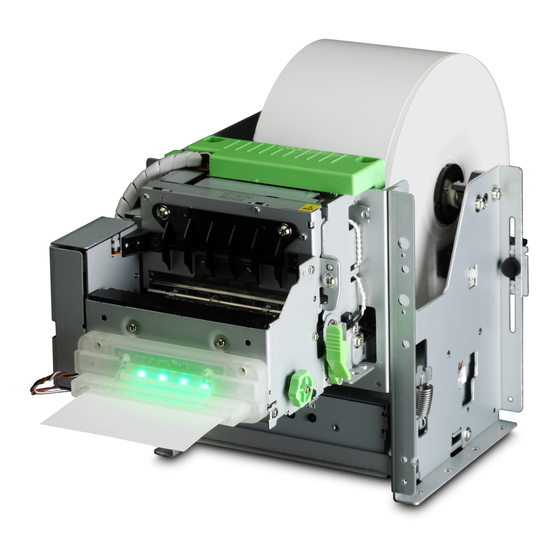
1. GENERAL DESCRIPTION The TUP500 series is a line-thermal unit printer capable of high speed printing that employs a thermal line dot printing system and is composed of a unit comprising thermal roll paper storage. This type is used, embedded in electronic devices such as games, ATM, and information kiosks. -
Page 6: Configuration
This is composed of the connector that connects the optional power adapter set to the control board, and the power switch. 2.1.6. Roll Paper Supply Module This supports the thermal roll paper on a shaft and functions to supply paper to the thermal mechanism module. TUP500 Series Product Specifications... -
Page 7: Optional Parts Selectable For The Modules
IFBD - HU05 Control PCB TBD500-24-A TMP542-24-A Presenter Unit PR521-24-A Damper Roller B Unit DRU-T500B Power PCB PBD-5 Near-end Sensor Unit NEU-T500 Operation PCB Unit OPA-T900 TBD500-24-A IFBD - HD03 TBD500-24J1-A IFBD-HC03 IFBD-HN03 IFBD-HE05 IFBD - HU05 TUP500 Series Product Specifications... -
Page 8: Basic Specifications
82.5 mm. Maximum 49 Positions 12 x 24 fonts Maximum 65 Positions 9 x 24 fonts Maximum 37 Positions 16 x 24 fonts Maximum 24 Positions 24 x 24 fonts *Only for Chinese Characters (6) Character Spacing TUP500 Series Product Specifications... - Page 9 Friction Feed Method Presenter Module Roller Friction Feed Method Note Models not equipped with a presenter adopt the thermal mechanism paper feed specifications. (9) Paper Feed Pitch: 0.125 mm *Paper feed pulse motor step (2-2 Phase Excitation) TUP500 Series Product Specifications...
- Page 10 (12) Print Head: Line Thermal Print Head (13) Presenter: With Recovery Function Notes: This does not apply to models not installed with the presenter. (14) Emulation: (1) Star Line Mode (2) Star Page Mode (3) ESC/POS Mode TUP500 Series Product Specifications...
-
Page 11: Character Specifications And Bar Code Specifications
1.5mm x 3mm Note Conforms to GB2312 JIS First and Second Standard Chinese Characters conform to JIS X 0208-1990/-1997. <Installed Bar Codes> 1D Bar UPC-A Codes UPC-E JAN/EAN-8 JAN/EAN-13 CODE39 CODE93 CODE128 CODABAR(NW-7) 2D Bar PDF417 Codes TUP500 Series Product Specifications... -
Page 12: Star Page Mode
1.5mm x 3mm Note Conforms to GB2312 JIS First and Second Standard Chinese Characters conform to JIS X 0208-1990/-1997. <Installed Bar Codes> 1D Bar UPC-A Codes UPC-E JAN/EAN-8 JAN/EAN-13 CODE39 CODE93 CODE128 CODABAR(NW-7) 2D Bar PDF417 Codes TUP500 Series Product Specifications... -
Page 13: Esc/Pos Mode
IBM Expanded Characters Note Conforms to GB2312 JIS First and Second Standard Chinese Characters conform to JIS X 0208-1990/-1997. <Installed Bar Codes> 1D Bar UPC-A Codes UPC-E JAN/EAN-8 JAN/EAN-13 CODE39 CODE93 CODE128 CODABAR(NW-7) 2D Bar PDF417 Codes TUP500 Series Product Specifications... -
Page 14: Paper Specifications
The shaft core material should be made of paper. If a plastic paper tube is used for the core material, the roll paper holder will be worn causing the core to come off of the holder. TUP500 Series Product Specifications... - Page 15 Depending on the type of paper used, the desired print quality may not be attained even if the head position is adjusted as described below. In such cases, try two head position settings and use with the position setting that gives you good results. Change the print density as required. TUP500 Series Product Specifications...
- Page 16 Carefully check the operations using your layout and print media. Sliding Direction Sliding Paper Guide Scale a Lever Scale b Scale c Scale d Fig. 3.3.1.7 Adjusting the Paper Guide TUP500 Series Product Specifications...
- Page 17 Depending on the thickness of the paper, its length and the ambient environment, it might be appropriate to mount at position (2). See Fig. 3.3.1.11. The loop guide will not be used, but keep it where you will not lose it. TUP500 Series Product Specifications 3-10...
- Page 18 Loop Guide Floating Cutter Loop Guide Weight Bar F ig. 3 .3.1 .8. F ig. 3 .3.1 .9. Positioning A Loop Guide Screw Screw Hooks F ig. 3.3.1.10. F ig. 3.3.1.11. TUP500 Series Product Specifications 3-11...
- Page 19 57.5±0.5 4 mm per side: Total 8 mm 50mm 79.5±0.5 4 mm per side: Total 8 mm 72mm 4 mm per side: Total 8 mm 74mm 82.5±0.5 1.25mm per side: Total 2.5 mm 80mm * TUP500 Series Product Specifications 3-12...
-
Page 20: Black Mark Specifications
F ig. 3 .3.2 . B la c k M ark S pecificatio ns (1) Black Mark Pitch (Dimension A) Black mark pitch can be set to the following range. CONFIGURA- Black Mark Pitch (Dimen- TION sion A) TUP592 75 to 300 mm TUP542 45 to 300 mm TUP500 Series Product Specifications 3-13... - Page 21 Use a setting printing range that will not exceed the black mark pitch. (10) Example Setting of the Printing Region The following shows a printing range setting example when not reverse feeding paper. TUP500 Series Product Specifications 3-14...
- Page 22 3mm + (100 mm × 0.03) = Min. 6 mm The print range of the paper feed direction should be max. 82mm. (10) Sensor Adjustment To use black marks, adjust the sensor with the black mark paper you use. TUP500 Series Product Specifications 3-15...
-
Page 23: Thermal Mechanism Module
Micro-switch Detects that the cover (between Head and Platen) is closed. (4) Cutter Home Position Detection: Micro-switch Notes: The paper out detector duals as the black mark detector. In such cases, some restrictions exist for black mark pitch detection. TUP500 Series Product Specifications 3-16... -
Page 24: Presenter Module
(1) Format: DC Brush Motor (2) Drive Voltage: 24 VDC ± 10% 3.5.3. Sensors (1) Paper Detector 1: Reflective Type Photo-sensor (2) Paper Detector 2: Reflective Type Photo-sensor (3) Paper Detector 3: Reflective Type Photo-sensor TUP500 Series Product Specifications 3-17... -
Page 25: Roll Paper Supply Module
F ig. 3.6.2.1. A dapter M ounting on the R oll P aper H older Notes: Adapter L is an accessory of the optional damper roller B unit (DRU-T500B), so if using the roll paper inner diameter Ø3 inch paper tube, purchase the optional damper roller B unit (DRU-T500B). TUP500 Series Product Specifications 3-18... - Page 26 See Fig. 3.6.2.2.C. for the roll paper holder (fastening side) setting position to handle paper widths of 79.5 mm. Position the edge of the roll paper holder onto the central position of the reference d position. Position the roll paper holder edge on the scale c F ig. 3.6.2.2.C . TUP500 Series Product Specifications 3-19...
- Page 27 The default setting support 1 inch paper tubes and paper widths 82.5 mm. If the setting position is incorrect, the roll paper will be supplied improperly to the mecha- nism which in turn causes paper transport problems. Thus, it is should be properly ad- justed. TUP500 Series Product Specifications 3-20...
-
Page 28: Near-End Detector
Therefore, design the frame so that the printer is unaffected by this light when this printer is used by being incorporated in a frame designed by the end user. TUP500 Series Product Specifications 3-21... -
Page 29: Reliability Specifications
300,000 Cuts Note: The contents above are values when using the recommended thermal paper. When using a different type of paper, reliability is not guaranteed. • Presenter Module Number of receipt issues: 1 million receipts TUP500 Series Product Specifications 3-22... - Page 30 Mechanical life is expressed as the number of lines in section 3.7.1. The number of lines of MCBF is not intended to represent service life. The above provides the numerical values for reliability specifications when all use the recommended thermal paper. Reliability cannot be guaranteed if different paper is used. TUP500 Series Product Specifications 3-23...
-
Page 31: External Specifications
See Fig. 4.1.2.A and Fig. 4.1.2.B. on the separate sheets. 4.1.3. Mass Unit Name Mass TUP592-24 Approx. 2.5 kg TUP542-24 Approx. 2.3 kg TMP542-24A Approx. 0.7 kg Notes: Weights do not include roll paper or accessories (including optional parts). TUP500 Series Product Specifications... - Page 32 (When using Ex. Diam. Ø150 Roll Paper) 246.3 (When NE Sensor Unit is Mounted) 234.1 (When NE Sensor Unit is Not Mounted) 117.5 116.8 17.1 PAPER WIDTH CENTER Power Connector I/F Option Power 116.8 17.1 124.2 Fig. 4.1.2.A. TUP592 External View TUP500 Series Product Specifications...
- Page 33 (Ext. Diam. Ø150 Roller Paper ) (When NE Sensor Unit is Mounted) (When NE Sensor Unit is Not Mounted) 116.8 17.1 PAPER WIDTH CENTER Power Connector I/F (Optional) 116.8 17.1 68.6 133.7 Fig. 4.1.2.B TUP542 External View TUP500 Series Product Specifications...
-
Page 34: Operating Unit Specifications
The direction for accessing the DIP switches will vary according to the layout of the con- trol board (card chassis). It is necessary to remove the card chassis (U) to access the DIP switches. See secton 12.1 for the DIP switch positions. TUP500 Series Product Specifications... -
Page 35: Ambient Specifications
(In the recommended packaging.) (1) Temperature: -20 to 60°C (2) Humidity: 10˚C to 90% RH (*No condensation) Note: The combination of 40°C and 90% RH (no condensation) is considered the worst values regarding high temperatures and humidity. TUP500 Series Product Specifications... -
Page 36: Emc (Electromagnet Compatibility)
Level 2 EN61000-4-4 (Voltage Peak: 1.0 KV) (Voltage Peak: 0.5KV) Repeat Ratio: 5 KHz) Repeat Ratio: 5 KHz) (4) Lightening Surge Test Testing Levels Standards Cited Line-to-Line Line-to-Earth Level 2 Level 3 EN61000-4-5 (Voltage: 1.0KV) (Voltage: 2.0KV) TUP500 Series Product Specifications... - Page 37 70% between 25/30 cycles 0% between 250/300 cycles (8) Impulse Noise Test Test Specifications Tolerance Level When Connected to PC Voltage: PE Phase 1 kV, L/N Phase 0.5 kV (ASCII continuous printing) Pulse Width: 100 ns TUP500 Series Product Specifications...
-
Page 38: Vibration/Falling Shocks
Tolerance Range of Setup Posture ±3° Notes: The printer was designed to conditions for a horizontal layout. If the printer I used when setup outside of the tolerance range, paper conveyance problems will occur and paper jams will occur. TUP500 Series Product Specifications... -
Page 39: Related Rules
2002/96/EC (The WEEE mark is a CENELEC EN50419 standard) • Packing and Packing Disposal Directives 94/62/EC Supports the following Chinese environmental ordinances. Electronics and Information Products Pollution Control Management Laws Requested Items (SJ/T 11363-2006, SJ/T 11364-2006, GB18455-2001) TUP500 Series Product Specifications... -
Page 40: Usage Example (Layout Example)
When using the printer outside of the recommended layout, printer performance some- times cannot be guaranteed. Design your layout to observe the layout precautions as outlined in this manual. To use a different layout that the one recommended, contact Star Micronics. TUP500 Series Product Specifications... -
Page 41: Horizontal Type Layout
Determine your final layout by actually trying to transport the type of paper you intend to use. To use the maximum diameter Ø254 roll paper, strictly observe the recommended layout. To use a different layout that the one recommended, contact Star Micronics. 7.2.2. Vertical Type Layout (1) This layout places the TUP500 and the optional large diameter roll paper holder (RHU-T500) in a vertical manner. - Page 42 (Ext. Diam 150 Roll Paper) 246.3 (When NE Sensor Unit is Mounted) 234.1 (When NE Sensor Unit is Not Mounted) 117.5 116.8 17.1 PAPER WIDTH CENTER 38.1 17.1 116.8 124.2 Fig. 7.1.1 Control Panel Layout 1 TUP500 Series Product Specifications...
- Page 43 (Ext. Diam Ø150 Roll Paper) (When NE Sensor Unit is Mounted) 246.3 234.1 (When NE Sensor Unit is Not Mounted) 117.5 116.8 17.1 PAPER WIDTH CENTER 38.1 116.8 17.1 124.2 Fig. 7.1.2 Control Panel Layout 2 TUP500 Series Product Specifications...
- Page 44 Sectional View E-E Fig. 7. 2. E xternal View of R H U-T500 TUP500 Series Product Specifications...
- Page 45 (Ext. Diam. Ø254 Roll Paper) Fig. 7.2.1.A. Horizontal Layout of TUP592 F ig. 7.2.1.A . H orizontal Layout of T U P 592 TUP500 Series Product Specifications...
- Page 46 F ig. 7.2.1.B . H orizontal Layout of TUP542 TUP500 Series Product Specifications...
- Page 47 Damper Roller Unit (Ex. Diam. Ø254 Roll Paper) F ig. 7.2.2.A . Vertical Layout of T U P 592 TUP500 Series Product Specifications...
- Page 48 Damper Roller Unit F ig. 7.2.2.B . Vertical Layout of T U P 542 TUP500 Series Product Specifications...
-
Page 49: Printer Setup
(see Fig. 7.2 on the separate sheet) to fasten both units. When doing so, align a with a’, b with b’, c with c’ and d with d’ for assembly. Also, it is recommended both using M4 screws and nuts with washers. TUP500 Series Product Specifications... - Page 50 The spring base comprised in the large diameter roll paper holder unit (RHU-T500) cannot be used in the vertical type layout. The friction springs (2 springs) will be fastened directly to the user side frame. TUP500 Series Product Specifications...
-
Page 51: Assembly Of The Large Roll Paper Holder Unit (Ruh-T500, Optional)
(RHUT500) so use the parts mounted on the printer. See section 8.5 for details on adjusting the position of the near-end sensor. TUP500 Series Product Specifications... - Page 52 The cable coming out from the near-end sensor unit should be clamp back so that it does not inter- fere with the roll paper. Also, when wiring the cable, adequately protect the material from the sharp edges of the frames. Fig. 8.2.2.D. shows the recommended cable path and clamping position. F ig. 8.2.1.A . TUP500 Series Product Specifications...
- Page 53 F ig. 8.2.1.B . TUP500 Series Product Specifications...
- Page 54 F ig. 8.2.1.C . TUP500 Series Product Specifications...
- Page 55 F ig. 8.2.1.D . TUP500 Series Product Specifications...
- Page 56 F ig. 8.2.1.E . TUP500 Series Product Specifications...
- Page 57 F ig. 8.2.2.A . TUP500 Series Product Specifications...
- Page 58 F ig. 8.2.2.B . TUP500 Series Product Specifications 8-10...
- Page 59 F ig. 8.2.2.C . TUP500 Series Product Specifications 8-11...
- Page 60 F ig. 8.2.2.D . TUP500 Series Product Specifications 8-12...
-
Page 61: Fastening The Friction Spring
Fit the friction spring between the top and bottom guide rail on the spring base to fasten the friction spring. At this time, be careful that the friction spring is not riding up on the guide rail when fastened. TUP500 Series Product Specifications 8-13... - Page 62 B and B’ so that the central position of the notch is not mis-positioned with the central position of the guide as shown in Fig. 8.3.1.C. Fasten the friction spring using the M3 screw. Position the notch on Position the notch on center of the scale center of the scale F ig. 8.3.1.C . TUP500 Series Product Specifications 8-14...
- Page 63 A so that the central position of the notch is not mis-positioned with the central position of the guide as shown in Fig. 8.3.1.E. Fasten the friction spring using the M3 screw. Position the notch on Position the notch on the center of the scale the center of the scale F ig. 8.3.1.E . TUP500 Series Product Specifications 8-15...
-
Page 64: When Not Using The Spring Base
(RHU-T500) and the friction spring layout. See the drawing to fasten the friction spring. Notes: Two M3 screws are recommended for fastening the friction spring. F ig. 8.3.2.A . F or 82.5 m m P aper W idth TUP500 Series Product Specifications 8-16... - Page 65 F ig. 8.3.2.B . F or 79.5 m m P aper W idth F ig. 8.3.2.C . F or 57.5 m m P aper W idth TUP500 Series Product Specifications 8-17...
- Page 66 F ig. 8.3.2.D . F or 45 m m P aper W idth TUP500 Series Product Specifications 8-18...
-
Page 67: Adjusting The Near-End Sensor Unit
(RHU-T500), is basically the same as that used in method (1). However, be aware that the difference in the setting position of the roll paper (the position to mount the roll paper bushing) makes the adjustment position different. TUP500 Series Product Specifications 8-19... - Page 68 [Ex. 2] When using a Ø25.4 paper core inner diameter on the vertical layout of item 7.2.2. Adjust the central position of the notch on the near-end sensor to the scale g shown in Fig. 8.5.2.B. TUP500 Series Product Specifications 8-20...
- Page 69 Width Direction Fixing Screw F ig. 8.4.1.A . 2 to 5 mm Roll Paper Edge Near-end Sensor Edge Near-end Sensor Movement Direction F ig. 8.4.1.B . TUP500 Series Product Specifications 8-21...
- Page 70 Width Direction Fixing Screw Scale c Fig. 8.4.2.A. Eyemark (1) Near-end Sensor Plate Eyemark (Notch) Scale a Scale b Scale c Scale d Scale e Scale f Scale g Scale h Scale i Scale j Fig. 8.4.2.B. TUP500 Series Product Specifications 8-22...
-
Page 71: Handling The Printer Unit
1, to securely lock it. At this time, it is dangerous to use the apparatus without it being completely locked, so be very careful. Notes: Also, when the frame for fastening the mechanism is closed, be careful not to get your hands or fingers caught. TUP500 Series Product Specifications... - Page 72 Handle F ig. 9.1.A . F ig. 9.1.B . TUP500 Series Product Specifications...
- Page 73 Thermal Side (Recording Side) F ig. 9.1.C . Bushing F ig. 9.1.D . TUP500 Series Product Specifications...
- Page 74 F ig. 9.1.E . TUP500 Series Product Specifications...
- Page 75 F ig. 9.1.F. Damper Roller Paper Insertion Inlet Paper Guide F ig. 9.1.G . TUP500 Series Product Specifications...
-
Page 76: Maintenance Method
See the following pages for releasing the cutter lock and opening the platen unit. Fig. 9.5.2 shows a schematic view of a model equipped with the presenter. TUP500 Series Product Specifications... -
Page 77: Releasing A Locked Cutter
Procedure (2) Rotate the emergency knobs in the direction of the arrows on the top of the auto-cutter unit case to return the cutter blades to their home position. The emergency knob should be rotated using a tweezers, screwdriver or ball-point pen to prevent accidents. TUP500 Series Product Specifications... -
Page 78: Precautions For Designing
(11) If the printing or paper feed are temporarily terminated, paper feeding may be disrupted in several dot lines when starting printing, when data is input and printing is started. This particularly affects printing bit images. TUP500 Series Product Specifications... - Page 79 Paper Discharge Guide F ig. 9.3 TUP500 Series Product Specifications...
-
Page 80: Precautions For Handling
Avoid sudden changes of the environment even if the ambient temperature and humidity are within standard. (21) Do not store or use the printer in locations that are dusty, oily or exposed to metallic dust. TUP500 Series Product Specifications 9-10... - Page 81 Never unnecessarily disassemble the printer or its parts. When performing maintenance, always check that the power has been turned OFF before starting your work. (25) The TUP500 series handles all paper widths within specifications. However, the width of paper on the same mechanism (auto-cutter) is limited to one type. (26) LPS electrical power is used as the drive power for this printer.
-
Page 82: Precautions Concerning Safety
Control Council for Interference by Information Technology Equipment (VCCI). There is the possibility that using this printer in a home environment can cause electromagnetic interference. In such cases, the user may be required to take the appropriate steps to remedy the situation. TUP500 Series Product Specifications 9-12... -
Page 83: Circuit General Specifications
Peak: Approx. 5.9 A Peak: Approx. 7.4 A Average: Approx. 1.1 A Average: Approx. 2.9 A Low Peak Current Mode Peak: Approx. 4.4 A Peak: Approx. 4.6 A (*) Continuous mat printing should be within 10 seconds. TUP500 Series Product Specifications 10-1... -
Page 84: Circuit Configuration
Presenter Driver Flash ROM 1MByte x 16 bits Sensor Sensor Circuit SRAM 256KByte x 8 bits External Device Driver 256KByte SRAM x 8 bits External Device +3.3V 3 Pin Regulator DC-DC Converter +24V Sub-board Power Unit TUP500 Series Product Specifications 11-1... -
Page 85: 1 .2 . Description Of Units
The printer mechanism is composed of a print head, paper feed motor, detectors, a presenter and paper feed unit. (12) External Device Preparation is not particularly prescribed, but I/O (open drain) for general use and an I/O are available on the control board. TUP500 Series Product Specifications 11-2... -
Page 86: Circuit Connection Specifications
CN33: For NE Sensor (Photo-sensor) Connection CN42: For Operation Panel Connection CN34: For External Drive Circuit Connection CN11: For Sub-board Connection CN22: For Head Drive CN21: For Head Drive CN23: For Mechanism Drive CN31: For Presenter Unit Drive TUP500 Series Product Specifications 12-1... - Page 87 Functions Not Connected P-GND Not Connected Not Connected P-GND M-GND Head Data Latch Signal P-GND Not Connected Head Data Transfer Clock P-GND M-GND N. C. Not Connected Remarks Compatible Cable: 30723190 Cable U (B) TMP5 TUP500 Series Product Specifications 12-2...
- Page 88 Sensor Detection Signals S-GND GND- Compatible Housing: PHR-2 Japan Solderless Terminal Remarks Compatible Cable: SPH-002T-P0.5 S (Japan Solderless Terminal) Example Spare Sensor (Mechanical Type) Circuit P H R -2 O P T G N D TUP500 Series Product Specifications 12-3...
- Page 89 S-GND Remarks Compatible Cable: 30721070 Cable U 3 x 900 C TUP9 NE Sensor (Photo-sensor) Circuit P H R -4 V C C V C C G P 2S 40 220 1/10W G N D TUP500 Series Product Specifications 12-4...
- Page 90 G L3K G 8 G L3K G 8 G L3K G 8 TR 1 O U T1 K TC 3875 TR 2 O U T2 K TC 3875 M-G N D N . C . 5,6,7,8,9,10 TUP500 Series Product Specifications 12-5...
- Page 91 Signal Name Signal Name Description) Description) Pin Signal 3.3V 3.3V Paper Feed Switch Names and Functions S-GND LED2 ERROR LED LED1 POWER LED Error Cancel Switch Compatible Housing: PHR-6 (JST) Remarks Compatible Connector: SPH-002T-P0.5 S (JST) TUP500 Series Product Specifications 12-6...
-
Page 92: Sub-Board
Used Function (General Function (General Pin Signal Signal Name Signal Name Description) Description) Names and Functions +24V M-GND Compatible Housing: 51144-0200 (Compatible Terminal: 50539-8000) Remarks Compatible Cable: 30721450 Cable U 2 x 60 CC TSP8 TUP500 Series Product Specifications 12-7... -
Page 93: Operation Board
Pin Signal 3.3V 3.3V Paper Feed Switch Names and Functions LED1 POWER LED (Green) Error Cancel Switch LED2 ERROR LED (Red) S-GND S-GND Compatible Housing: PHR-6R Remarks Compatible Housing: 30721760 Cable U 6X220CC TUP9 TUP500 Series Product Specifications 12-8... -
Page 94: External Drawing
12.2. External Drawing 12.2.1. Main Board +0.1 2- 3.7 +0.1 CN41 2-0.8 6- 2 +0.1 TUP500 Series Product Specifications 12-9... -
Page 95: Sub-Board
12.2.2. Sub-board +0.1 +0.1 18.5 TUP500 Series Product Specifications 12-10... -
Page 96: Operation Board
12.2.3. Operation Board TUP500 Series Product Specifications 12-11... -
Page 97: Circuit Example
12.3. Circuit Example See the circuit diagrams for TBD500 and PBD-5, OPA-T900. TUP500 Series Product Specifications 12-12... -
Page 98: Dip Switch Specifications
DIPSW1-5 USB Mode Printer Class Vendor Class DIPSW1-6 BUSY Condition Reception Buffer Full/OFF-LINE Reception Buffer Full DIPSW1-7 (Reserved) DIPSW1-8 NE Sensor Contact State (*3) Non-contact Contact DIPSW1-9 Low Peak Current Mode Invalid Valid DIPSW1-10 (Reserved) TUP500 Series Product Specifications 13-1... - Page 99 STAR Line Mode STAR Page Mode (Reserved) ESC/POS Mode *3) NE Sensor Connection Be aware that operations are not guaranteed if the state set using this bit and the actual NE sensor contact state are different. TUP500 Series Product Specifications 13-2...
- Page 100 13.2 . Main Board DIPSW 2 DIPSW2 Function DIPSW2-1 (Reserved) DIPSW2-2 (Reserved) DIPSW2-3 (Reserved) DIPSW2-4 (Reserved) TUP500 Series Product Specifications 13-3...
-
Page 101: 3 .3 . Rs232 Interface Board Dipsw
DIPSW1-4 Parity Check Invalid Valid DIPSW1-5 Parity Selection Even DIPSW1-6 Handshake DTR Mode Xon/Xoff Mode DIPSW1-7 (Reserved) DIPSW1-8 (Reserved) *1) Baud Rate Settings DIPSW1-1 DIPSW1-2 Baud Rate 9600 bps 4800 bps 19200 bps 38400 bps TUP500 Series Product Specifications 13-4... -
Page 102: Msw Specifications
Mode Invalid Invalid Japanese Character ANK Mode (When MSW 0-5 = “1”) Valid Invalid SHIFT-JIS Chinese Character Mode (When MSW 0-5 = “0”) Invalid Valid JIS Chinese Character Mode Valid Valid JIS Chinese Character Mode TUP500 Series Product Specifications 14-1... - Page 103 If SHIFT-JIS/JIS mixed mode is selected, the printer processes data as 2-byte code. When JIS Mode is selected, and the reception data is 0 x 21-0x7E, it processes reception data as 2-byte code along with the next data. TUP500 Series Product Specifications 14-2...
- Page 104 • When installed with Hangul (Korean) characters, the international character setting is fixed to “Korea (n = 13)” as default. *2) Font Types (Font-A, Font-B) Large font settings can be made independently in Star Line mode and ESC/POS mode. TUP500 Series Product Specifications 14-3...
- Page 105 “0” 11mm Standard Top Page “1” After full cut, executes return feed prior to printing “2” 13mm Adds 2mm of empty space to top of print after a full cut. “3” 11mm Standard Top Page TUP500 Series Product Specifications 14-4...
- Page 106 Low Speed: Max. 80 mm/sec “3” High Speed: Max. 220 mm/sec However, when the print region setting is less than 72 mm, the maximum is 180 mm/sec. See section 3.1 Print Specifications for details on other restrictions. TUP500 Series Product Specifications 14-5...
- Page 107 <GS> V n, <GS> V m n Page mode is invalid. BM Detection Command: <GS><FF>, <FF> (When BM is valid.) Invalid during macro Print Startup Command: <ESC><GS> g a m n (a=0) registration and execution TUP500 Series Product Specifications 14-6...
- Page 108 30 (3+24+3) dot 19 Positions Character MSW3-4 Character Character Sizes Font-A Printing Positions Types (Font + Right Space) (When Print Region is set to 72 mm) 13 (12+1) dot 44 Positions 15 (12+3) dot 38 Positions TUP500 Series Product Specifications 14-7...
- Page 109 (reserved) “4E” Codepage 3021 (Bulgarian) (reserved) “4F” Codepage 3041 (Maltese) (reserved) “FF” User Setting ← (Blank Code Page) This function is valid only when set for SBCS and DBCS setting is fixed to code page. TUP500 Series Product Specifications 14-8...
- Page 110 42mm “2B” 43mm “2C” 44mm “46” 70mm “47” 71mm “48” 72mm “49” 73mm “4A” 74mm “4B” 75mm “4C” 76mm “4D” 77mm “4E” 78mm “4F” 79mm “50” 80mm “51” 72mm “52” 72mm “FE” 72mm “FF” 72mm TUP500 Series Product Specifications 14-9...
- Page 111 *2) Print Mode When DIPSW1-9 Low Peak Current mode is valid, this setting is ignored and Low Peak Current mode is set. MSW4-9 MSW4-8 Print Mode “0” Single-color “1” 2-colors “2” Double Resolution “3” (Reserved) TUP500 Series Product Specifications 14-10...
- Page 112 MSW5-F MSW5-E Snout Function “0” Snout Function OFF “1” Snout Function ON (When printing and presenter is operating) “2” Snout Function ON (Error) “3” Snout Function ON (When printing and presenter is operating + Error) TUP500 Series Product Specifications 14-11...
- Page 113 • When printing and presenter is operating ON Time: 100 msec; Off: 100 msec • ERROR: ON Time: 100 msec; Off: 100 msec This MSW is valid only when the presenter and snout are connected. When the snout is not connected, the snout function cannot turn ON. TUP500 Series Product Specifications 14-12...
- Page 114 Use this function to select to enable retry. Also, when a presenter is installed, auto-loading is possible if paper is pulled out once, without a presenter paper jam error occurring, even if auto-loading fails. A presenter paper jam error occurs when auto-loading fails when retry is disabled. TUP500 Series Product Specifications 14-13...
- Page 115 *2) ASB Functions This function is valid only when using a serial I/F, parallel I/F and USB I/F. MSW7-C ASB Functions Parallel, Serial ASB Invalid USB Vendor Class ASB Valid USB Printer Class ASB Valid ASB Invalid TUP500 Series Product Specifications 14-14...
- Page 116 Specifies Format Loaded When (See table below) × ○ × Power is Turned ON Specifies Format Loaded When Power is Turned ON MSW8-1 MSW8-0 “0” No format specified “1” Specifies format 1 “2” Specifies format 2 “3” (Reserved) TUP500 Series Product Specifications 14-15...
- Page 117 *4) NE Sensor Input Signal Level This function specifies the NE sensor input signal level when NE is outputting. Valid only when an NE sensor is connected. (The NE sensor is set using DIPSW1-8.) ) TUP500 Series Product Specifications 14-16...
-
Page 118: Operating Specifications
No Switch Input: PE/BM Sensor Adjustment Mode Presenter Sensor Adjustment Mode NE Sensor Adjustment Mode When ONLINE Paper Conveyed While SW is Input Printer Reset (Hold 2 Seconds) Error Error Cancelled Paper Discharge Printer Reset (Input 2 Seconds) TUP500 Series Product Specifications 15-1... - Page 119 However, this function can damage the print head so do not over use it. Push Push Executes printer reset. After pushing SW2, push SW1. (2 Secs.) (2 Secs.) TUP500 Series Product Specifications 15-2...
-
Page 120: 5 .2 . Led Specifications
Non-recoverable Error → Recoverable Error → Auto-recover Error → Warning Display → On-Line <LED Output Example Cutter Error > Cutter Error > Cutter Error > Power LED (Green) Error LED (Red) Flashing Flashing Flashing Cycle: Cycle Cycle T = 0.125 sec TUP500 Series Product Specifications 15-3... -
Page 121: 5 .3 . Error Specifications
3-2-3) Auto-loading Operation Startup 4) Online Recovery Operation Execution BM Error Flashing Cycle Black Mark Paper Size Error Replace Black Mark Paper for 1.0 seconds (White detected over 400 mm long) Readjust with Sensor Adjustment Mode TUP500 Series Product Specifications 15-4... -
Page 122: Non-Recoverable Errors
Detection of Head Thermistor Erroneous Value Repair Error for 3.0 seconds Power Voltage Errors Flashing Cycle Power Voltage Error Value Detected 1) Power OFF for 4.0 seconds 2) Check power status 3) Power ON 4) Same error occurs 5) Repair TUP500 Series Product Specifications 15-5... -
Page 123: 5 .4 . Sensor Adjustment Mode Specifications
It is necessary to adjust each time the printer enters the sensor adjustment mode. There is a point where the LED flashes instantly. That is not an adjustment position. There is a point where the LED lights completely. That is the adjustment position. TUP500 Series Product Specifications 15-6... -
Page 124: Command Specifications And Character Codes
COMMAND SPECIFICATIONS AND CHARACTER CODES 16.1 . STAR Line Mode Refer to the “STAR Line Mode Command Specifications for Line Thermal Printers” for details. TUP500 Series Product Specifications 16-1... - Page 125 16.2 . STAR Page Mode Refer to the “STAR Page Mode Command Specifications for Line Thermal Printers” for details. TUP500 Series Product Specifications 16-2...
- Page 126 16.3 . ESC/POS Mode Refer to the “ESC/POS Mode Command Specifications for Line Thermal Printers” for details. TUP500 Series Product Specifications 16-3...
- Page 127 OVERSEAS SUBSIDIARY COMPANIES SPECIAL PRODUCTS DIVISION STAR MICRONICS AMERICA, INC. STAR MICRONICS CO., LTD. 1150 King Georges Post Road, Edison, NJ 08837-3729 536 Nanatsushinya, Shimizu-ku, Shizuoka, U.S.A. 424-0066 Japan Tel: (int+1)-732-623-5555, Fax: (int+1)-732-623-5590 Tel: (int+81)-54-347-0112 Fax: (int+81)-54-347-0409 STAR MICRONICS EUROPE LTD.