Star Micronics TSP100LAN Hardware Manual
Tsp 100 futureprnt
Hide thumbs
Also See for TSP100LAN:
- Manual (36 pages) ,
- Software manual (173 pages) ,
- Hardware manual (37 pages)

Related Manuals for Star Micronics TSP100LAN


Summary of Contents for Star Micronics TSP100LAN
- Page 1 TSP100LAN Hardware Manual...
- Page 2 Low Voltage Directive of the European Communities as of 2001. The above statement applies only to printers marketed in EU. Trademark acknowledgments TSP100LAN: Star Micronics Co., Ltd. Notice • All rights reserved. Reproduction of any part of this manual in any form whatsoever, without STAR’s express permission is forbidden.
-
Page 3: Table Of Contents
TABLE OF CONTENTS 1. Unpacking and Installation ........................1 1-1. Unpacking ..............................1 1-2. Choosing a place for the printer ......................2 2. Parts Identification and Nomenclature ....................3 3. Setup ..............................4 3-1. Connecting the Ethernet Cable to the Printer ..................4 3-2. -
Page 4: Unpacking And Installation
1. Unpacking and Installation 1-1. Unpacking After unpacking the unit, check that all the necessary accessories are included in the package. LAN cable Switch cover Power cord Paper roll holder Screws Rubber feet CD-ROM Holder plate Installation sheet Printer Roll paper Fig. -
Page 5: Choosing A Place For The Printer
1-2. Choosing a place for the printer Before actually unpacking the printer, you should take a few minutes to think about where you plan to use it. Remember the following points when doing this. ✓ Choose a firm, level surface where the printer will not be exposed to vibration. ✓... -
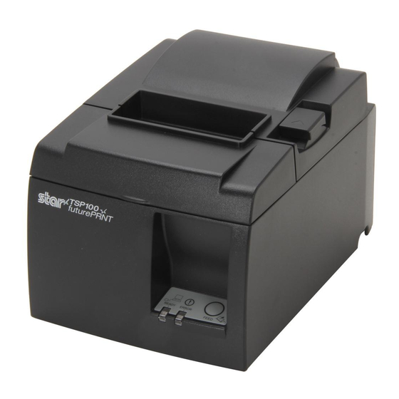
Page 6: Parts Identification And Nomenclature
2. Parts Identification and Nomenclature Printer cover Open this cover to load or replace paper. Cover open lever Pull this lever in the direction of the arrow to open the printer cover. Power switch Used to turn on/off Control panel power to the printer. -
Page 7: Setup
3. Setup 3-1. Connecting the Ethernet Cable to the Printer (1) Make sure the printer is turned off. (2) Connect the ethernet cable to the connector on the rear panel of the printer. – 4 –... -
Page 8: Connecting To A Peripheral Unit
3-2. Connecting to a Peripheral Unit You can connect a peripheral unit to the printer using a modular plug. The following describes how to install the ferrite core and make the actual connection. See “Modular plug” on page 25 for details about the type of modular plug that is required. Note that this printer does not come with a modular plug or wire, so it is up to you to obtain one that suits your needs. -
Page 9: Loading The Paper Roll
3-3. Loading the Paper Roll 3-3-1. Using 79.5 mm Width Paper Roll Be sure to use roll paper that matches the printer’s specification. When using a paper roll with an 57.5 mm width, install the paper roll holder as described on the following page. - Page 10 3-3-2. Using 57.5 mm Width Paper Roll When using a paper roll with 57.5 mm width, install the supplied paper guide on the printer. To change the effective print width (roll paper width), change the setting of the Print Width in the Configuration.
- Page 11 Caution Symbol A label with these symbols is placed near the thermal head. Never touch the ther- mal head immediately after printing, because it may be hot. Never touch the thermal head with your hands because it can generate static elec- tricity, which can damage the device in the thermal head.
-
Page 12: Connecting The Ethernet Cable To The Pc
12) Do not forcibly pull on the interface cable, power cable, or cash drawer cable that is connect- ed. To detach a connector, make sure to grasp it at the connector portion, without applying excessive stress on the connector at the printer. Notes on Using the Auto Cutter 1) To print after a cut, feed 1 mm (8-dot line) or more of paper. -
Page 13: Installing The Printer Software
3-5. Installing the Printer Software Here is the procedure for installing the printer driver and utility software, which are stored on the supplied CD-ROM. The procedure applies to the Windows operating systems shown below. • Windows 2000 • Windows XP •... -
Page 14: Connecting The Power Cord
3-6. Connecting the Power Cord Note: Before connecting/disconnecting the power cord, make sure that power to the printer and all the devices connected to the printer is turned off. Also make sure the power cable plug is disconnected from the AC outlet. (1) Check the label on the back or bottom of the printer to make sure its voltage matches that of the AC outlet. -
Page 15: Turning Power On
3-7. Turning Power On Make sure that the Power cord has been connected as described in 3-6. Turn ON the power switch located on the left side of the printer. When the switch is turned ON, the READY lamp will flash on the control panel. The READY lamp will light up when the printer is connected to the network. -
Page 16: Attaching The Accessories
4. Attaching the Accessories The following accessories do not necessarily have to be attached. Attach them if necessary. • Holder plate • Rubber feet • Switch cover 4-1. Attaching the Holder Plate • The holder plate is attached to the printer using the included screws and is hooked onto screws that are installed into the wall. - Page 17 (1) Attach the holding plate to the printer. Then tighten the two screws that were supplied to secure it in place. (2) Position the printer over the screws, etc., on the wall and then slide it downward to set it in place. 2 to 3 mm After setting the printer in place, check the screws on the wall again to make sure...
-
Page 18: Attaching The Rubber Feet
4-2. Attaching the Rubber Feet (1) Attach the four rubber feet in the positions shown in the figure. Ensure that any soiling has been completely wiped off before attaching the rubber feet. (2) Push the cover open lever, and open the printer cover. -
Page 19: Switch Cover Installation
4-3. Switch Cover Installation It is not necessary to install the switch cover. Only install it if it is necessary for you. By installing the switch cover, the following become possible. • Preventing the power switch from being operated by mistake. •... -
Page 20: Thermal Roll Paper Specification
5. Thermal Roll Paper Specification When consumable parts have run out, use those specified below. 5-1. Roll paper specification Thermal paper Thickness: 65~85 µm (excluding Mitsubishi HiTec F5041) Width: 79.5±0.5 mm (57.5±0.5 mm when the paper roller holder is used) Outer roll diameter: ø83 mm or less Take up paper roll width: 80 mm or (58 mm when the paper roller holder is used) + 0.5... -
Page 21: Control Panel And Other Functions
6. Control Panel and Other Functions 6-1. Control Panel 1 READY lamp (Green LED) Lights up when the printer is properly con- nected to the network. 2 ERROR lamp (Red LED) Indicates various errors in combination with POWER lamp. 3 FEED button 3 FEED button 2 ERROR lamp (Red LED) Press the FEED button to feed roll paper. - Page 22 3) Paper cut error Error Description READY Lamp ERROR Lamp Recovery Conditions Paper cut error Flashes at Recovered by turning the power OFF, 0.125-second eliminating the cause of the error such as intervals jammed paper, returning the cutter to its home position, and turning the power ON (see 7-3).
-
Page 23: Self-Printing
6-3. Self-Printing Test Printing Turn the power ON while holding the FEED button depressed. Test printing is performed. The version number, the switch settings and the network informations are printed. After the printer starts printing, release your hand from the FEED button. After self-printing is completed, the printer will start in the normal mode. -
Page 24: Preventing And Clearing Paper Jams
7. Preventing and Clearing Paper Jams 7-1. Preventing Paper Jams The paper should not be touched during ejection and before it is cut. Pressing or pulling the paper during ejection may cause a paper jam, paper cutting failure or line feed failure. 7-2. -
Page 25: Releasing A Locked Cutter (Auto Cutter Mode Only)
7-3. Releasing a Locked Cutter (Auto Cutter Mode only) If the auto cutter locks up or fails to cut the paper, follow the steps below. WARNING Since working on the cutter may be dangerous, be sure to turn off the printer first. (1) Set the power switch to OFF to turn off the printer. - Page 26 (4) If the cutter is locked, insert a Philips screwdriver into the Philips screw hole on the side of the cutter, and turn it in the direction of the arrow shown on the right, in order to return the cutter to its normal position. (5) Open the printer cover, remove any jammed paper, and then reinstall the paper roll.
-
Page 27: Periodical Cleaning
8. Periodical Cleaning Printed characters may become partially unclear due to accumulated paper dust and dirt. To prevent such a problem, paper dust collected in the paper holder and paper transport section and on the surface of the thermal head must be removed periodically. Such cleaning is recommended to be carried out once six month or one million lines. -
Page 28: Peripheral Unit Drive Circuit
9. Peripheral Unit Drive Circuit Peripheral unit drive circuit connector only connects to peripheral units such as cash drawers, etc. Do not connect it to a telephone. Use cables which meet the following specifications. Peripheral Drive Connector Signal Modular plug Pin No. - Page 29 Notes: 1. Pin 1 must be shield drain wire connected to peripheral device frame ground. 2. It is not possible to drive two drives simultaneously. 3. The peripheral drive duty must satisfy the following: ON time / (ON time + OFF time) 0.2 4.
-
Page 30: Specifications
10. Specifications 10-1. General Specifications (1) Printing method Direct line thermal printing (2) Print speed Max. 1000 dots/sec. (125 mm/sec.) (3) Dot density 203 dpi: 8 dots/mm (0.125 mm/dot) (4) Printing width Max. 72 mm (5) Roll paper Refer to chapter 5 for details on the recommended roll paper. Paper width:79.5±0.5 mm (57.5±0.5 mm when the paper roll holder is used) Roll diameter: ø83 mm or less... -
Page 31: Auto Cutter Specifications
10-2. Auto Cutter Specifications (1) Cutting frequency Max. 20 cuts per minute 65~85 µm (2) Thickness of paper 10-3. Ethernet Interface (1) General Specification Conforms to IEEE802.3 / Conforms to IEEE802.3u (2) Communication Media 10 Base-T / 100 Base-TX (3) Communication Speed 10 / 100 Mbps (4) Protocol TCP/IP v4... -
Page 32: Environmental Requirements
10-5. Environmental Requirements (1) Operating Temperature 5°C to 45°C Humidity 10% to 90% RH (without condensation) (%RH) 34°C90% RH 40°C65% RH 45°C50% RH Ope rating e nvironment range Temperature (°C) Ope rating tempe rature and humidity range (2) Transport/storage (except for paper) Temperature -20°C to 60°C Humidity... -
Page 33: Reliability
10-6. Reliability 1) Life Mechanical : 20 million lines Head : 100 million pulses, 100 km (±15% max. average head resistance fluctuation) For 2-color printing, 50 million pulses, 50 km (±15% max. average head resistance fluctuation) Auto cutter : 1 million cuttings (provided the paper thickness is between 65 and 85 µm) * All the reliability values indicated above are based on the use of the recommended thermal paper. -
Page 34: Dip Switch Settings
11. DIP Switch Settings There are DIP switches located on the bottom of the printer and various settings can be per- formed as shown in the following table. When changing the settings, use the following procedure. (1) Turn the printer off and disconnect the power cable plug from the AC outlet. (2) Remove the screw, and then remove the DIP switch cover on the bottom of the printer. - Page 35 (4) Turn switch 1-4 ON and turn the printer power ON. Note: The following functions are disabled when switch 1-4 is OFF. Therefore, make sure to turn switch 1-4 back ON. • Printing (However, test printing is enabled.) • TELNET server –...
- Page 36 OVERSEAS SUBSIDIARY COMPANIES STAR MICRONICS AMERICA, INC. 1150 King Georges Post Road, Edison, NJ 08837-3729 U.S.A. Tel: (int+1)-732-623-5555, Fax: (int+1)-732-623-5590 ELECTRONIC PRODUCTS DIVISION STAR MICRONICS EUROPE LTD. STAR MICRONICS CO., LTD. Star House, Peregrine Business Park, Gomm Road, 536 Nanatsushinya, Shimizu-ku, Shizuoka, High Wycombe, Bucks, HP13 7DL, U.K.