Table of Contents
Advertisement
R410A Full DC Inverter Split Duct Type Technical Manual
MCAC-UTSM-201503
R410A Full DC Inverter Split Duct 50Hz
Side Air-discharge Type
Service Manual
Applicable Model:
Indoor unit
Outdoor unit
MHC-96HWD1N1(A)
MOUA-96HD1N1-R
Midea reserves the right to discontinue, or change specification or designs at any time without
notices and without incurring obligations.
Advertisement
Chapters
Table of Contents
Troubleshooting

Related Manuals for Midea MHC-96HWD1N1(A)


Summary of Contents for Midea MHC-96HWD1N1(A)
- Page 1 R410A Full DC Inverter Split Duct 50Hz Side Air-discharge Type Service Manual Applicable Model: Indoor unit Outdoor unit MHC-96HWD1N1(A) MOUA-96HD1N1-R Midea reserves the right to discontinue, or change specification or designs at any time without notices and without incurring obligations.
-
Page 2: Table Of Contents
R410A Full DC Inverter Split Duct Type Technical Manual MCAC-UTSM-201503 Content Part. 1 General information ......2 Part. 2 Outdoor Unit ........5 Part. 3 Indoor Unit ......... 11 Part. 4 Installation & Troubleshooting ..23 Part. 5 Controller ........... 53... -
Page 3: Part. 1 General Information
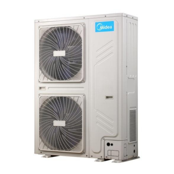
MCAC-UTSM-201503 R410A Full DC Inverter Split Duct Type Technical Manual Part. 1 General information 1. Model Names of Indoor/Outdoor Units ........3 2. External Appearance ............. 3 3. Nomenclature ............... 4... - Page 4 R410A Full DC Inverter Split Duct Type Technical Manual MCAC-UTSM-201503 1. Model Names of Indoor/Outdoor Units Indoor unit Outdoor unit Type Model Power supply Model Power supply Hi-static pressure 220-240V~, 1Ph, MHC-96HWD1N1(A) MOUA-96HD1N1-R 380-415V~, 3Ph, 50Hz duct type 50Hz 2. External Appearance 2.1 Indoor units MHC-96HWD1N1(A) 2.2 Outdoor unit...
- Page 5 H: Heat pump Nominal cooling capacity (96×1,000Btu/h) Series number: C type High static pressure duct type Midea 3.2 Outdoor unit: M O U A - 96 H D1 N1 - R Power supply: 380~415V 3Ph 50Hz Refrigerant type - N1: R410A...
-
Page 6: Part. 2 Outdoor Unit
R410A Full DC Inverter Split Duct Type Technical Manual MCAC-UTSM-201503 Part. 2 Outdoor Unit 1. Specifications ..............6 2. Dimension (Unit:mm) ............7 3. Refrigerant circuit ..............8 4. Wiring Diagrams ..............9 5. Electric Characteristics ............9 6. Sound Levels ..............10 7. -
Page 7: Specifications
MCAC-UTSM-201503 R410A Full DC Inverter Split Duct Type Technical Manual 1. Specifications Model MOUA-96HD1N1-R Power supply V, Ph, Hz 380-415V~, 3Ph, 50Hz Ambient temp in cooling ° C -15~48 Ambient temp in heating ° C -15~24 Rated input (Whole units) 11,700 Rated current (Whole units) Compressor... -
Page 8: Dimension (Unit:mm)
R410A Full DC Inverter Split Duct Type Technical Manual MCAC-UTSM-201503 2. Dimension (Unit:mm) 1120... -
Page 9: Refrigerant Circuit
MCAC-UTSM-201503 R410A Full DC Inverter Split Duct Type Technical Manual 3. Refrigerant circuit Electronic Condensor expansion valve High pressure switch High pressure liquid accumulator Oil seperator Evaporator Oil return capilary Compressor Low pressure Low pressure switch liquid accumulator can... -
Page 10: Wiring Diagrams
R410A Full DC Inverter Split Duct Type Technical Manual MCAC-UTSM-201503 4. Wiring Diagrams 5. Electric Characteristics Outdoor Unit Power Supply Compressor Model Voltage Min. Max. TOCA MOUA-96HD1N1-R 380-415V 342V 440V 15.4 0.17 Remark: MCA: Min. Current Amps. (A) TOCA: Total Over-current Amps. (A) MFA: Max. -
Page 11: Sound Levels
MCAC-UTSM-201503 R410A Full DC Inverter Split Duct Type Technical Manual 6. Sound Levels Front 1.3m Unit Number Model Noise level under three speeds of fan (dB(A)) MOUA-96HD1N1-R 7. Accessories Accessory name of outdoor unit Qty. Purpose Connection pipe Connecting pipe of system Curved connection pipe... -
Page 12: Part. 3 Indoor Unit
R410A Full DC Inverter Split Duct Type Technical Manual MCAC-UTSM-201503 Part. 3 Indoor Unit 1. Features ................12 2. Specifications ..............13 3. Dimensions (Unit: mm) ............14 4. Wiring Diagrams ..............15 5. Capacity Table ..............18 6. Static Pressure Curve ............19 7. -
Page 13: Features
MCAC-UTSM-201503 R410A Full DC Inverter Split Duct Type Technical Manual 1. Features 1.1 Compace design & Convenient installation Convenient installation, hidden in the ceiling, unit installation is not hindered by the location of lighting fixtures or room structure. Air inlet and outlet flanges are standard and easy for duct connection. -
Page 14: Specifications
R410A Full DC Inverter Split Duct Type Technical Manual MCAC-UTSM-201503 2. Specifications Model MHC-96HWD1N1(A) Power supply V, Ph, Hz 220~240V,1Ph,50Hz Capacity 28,000 Cooling Input 9,000 3.11 Capacity 31,500 Heating Input 8,500 3.71 Rated input Rated current Model WZDK750-38GS-W Brand Panasonic Indoor fan motor Quantity Speed... -
Page 15: Dimensions (Unit:mm)
MCAC-UTSM-201503 R410A Full DC Inverter Split Duct Type Technical Manual 3. Dimensions (Unit:mm) Air outlet duct connection screw hole location diagram 1138 Return air duct rivet screw hole location diagram... -
Page 16: Wiring Diagrams
R410A Full DC Inverter Split Duct Type Technical Manual MCAC-UTSM-201503 4. Wiring Diagrams... - Page 17 MCAC-UTSM-201503 R410A Full DC Inverter Split Duct Type Technical Manual...
- Page 18 R410A Full DC Inverter Split Duct Type Technical Manual MCAC-UTSM-201503...
-
Page 19: Capacity Table
MCAC-UTSM-201503 R410A Full DC Inverter Split Duct Type Technical Manual 5. Capacity Table Cooling mode: Indoor temperature Outdoor temperature (DB ° C) DB (° C) WB (° C) 21.0 28.0 35.0 43.0 46.0 52.0 54.0 Tcc(kW) 28.84 27.44 26.04 24.92 24.08 22.68 21.00... -
Page 20: Static Pressure Curve
R410A Full DC Inverter Split Duct Type Technical Manual MCAC-UTSM-201503 6. Static Pressure Curve The corresponding table of electronic control dial code and static pressure range is shown below. For Setting Static pressure ENC2 Code 81~120 121~150 High static pressure 0~50 51~80 Factory Setting... - Page 21 MCAC-UTSM-201503 R410A Full DC Inverter Split Duct Type Technical Manual Static curve (ENC2) 2 High air Medium air Low air 3000 3500 4000 4500 5000 5500 6000 air flow (m Static curve (ENC2) 3 High air Medium air Low air 3000 3500 4000...
-
Page 22: Electric Characteristics
R410A Full DC Inverter Split Duct Type Technical Manual MCAC-UTSM-201503 7. Electric Characteristics Indoor Unit Power Supply Model Voltage Min. Max. MHC-96HWD1N1(A) 220-240V 198V 254V 0.75 Note: MCA: Min. Current Amps. (A) MFA: Max. Fuse Amps. (A) IFM: Indoor Fan Motor kW: Fan Motor Rated Output (kW) FLA: Full Load Amps. -
Page 23: Accessories
MCAC-UTSM-201503 R410A Full DC Inverter Split Duct Type Technical Manual 9. Accessories Accessory name of indoor unit Qty. Purpose Owner’ manual Installation manual Sealing tape Sealed tube interface Water connective pipe Connect to water drainage pipe Protective sleeve for refrigerant inlet and outlet pipes Wired controller Copper nut Connect to liquid-side pipe... -
Page 24: Part. 4 Installation & Troubleshooting
R410A Full DC Inverter Split Duct Type Technical Manual MCAC-UTSM-201503 Part. 4 Installation & Troubleshooting 1. Notes ................. 24 2. Installation of Duct Type Indoor Units ........ 25 3. Installation of Outdoor Units ..........29 4. Connection of Refrigerant Pipe .......... 32 5. -
Page 25: Notes
MCAC-UTSM-201503 R410A Full DC Inverter Split Duct Type Technical Manual 1. Notes CAUTION: Install the unit where enough space of installation and maintenance is available. Install the unit where the ceiling is horizontal and enough for bearing the weight of the indoor unit. ... -
Page 26: Installation Of Duct Type Indoor Units
R410A Full DC Inverter Split Duct Type Technical Manual MCAC-UTSM-201503 2. Installation of Duct Type Indoor Units 2.1 Installating space Ensure enough space required for installation and maintenance. (Unit:mm) Maintenance space 600mmX600mm Inspection orifice Gas side liquid side outlet Side view (Pipes) - Page 27 MCAC-UTSM-201503 R410A Full DC Inverter Split Duct Type Technical Manual 2.2 Install Φ10 pendant bolts or ground bolts Pendant bolt hole 4-12x25 (Unit:mm) Use Φ10 or bigger screws. The screw material is high-quality carbon steel (whose surface is zinc plated or undergoes other rustproof treatment) or stainless steel.
- Page 28 R410A Full DC Inverter Split Duct Type Technical Manual MCAC-UTSM-201503 C. New concrete roughcast Set it with embedded bushes or embedded bolts. D. Steel beam and girder structure Set and use supportive angle steel. Suspended bolt Supportive Pendant bolt angle steel 2.3 Suspending the indoor unit Use a hoisting device to hoist the indoor unit, align it with the installation screw, adjust the horizontality and then tighten it.
- Page 29 MCAC-UTSM-201503 R410A Full DC Inverter Split Duct Type Technical Manual especially in the noise-sensitive spaces such as meeting rooms. For connection of the flange plane, use non-flammable canvas adapter to prevent transmission of vibration. For its size, see the indoor unit outline diagram. Use M6X20 screws (configured on site) for connection.
-
Page 30: Installation Of Outdoor Units
R410A Full DC Inverter Split Duct Type Technical Manual MCAC-UTSM-201503 CAUTION Rubbish is easy to accumulate at drain stream trap. Make sure to install a plug or other things which is easy to clean. 2. Test draining Open the clapboard of indoor unit, pour the water in to see whether it drain smoothly and whether there is water leakage. - Page 31 MCAC-UTSM-201503 R410A Full DC Inverter Split Duct Type Technical Manual Parallel connect the front with rear sides >6000 >3000 >1000 >4000 >300 3.2 Moving and installation Since the gravity center of the unit is not at its physical center, so please be careful when lifting it with a sling.
- Page 32 R410A Full DC Inverter Split Duct Type Technical Manual MCAC-UTSM-201503 pipe to completecentralized drainage installation. Sealing ring for the water outlet union pipe Waterproof chassis cover 3.4 Install the connecting pipe of outdoor Check whether the height drop between the indoor unit and outdoor unit, the length of refrigerant pipe, and the number of the bends meet the following requirements: The indoor and outdoor connecting pipe interface and power line outlet Vavious piping and viring patterns can be selected,such as out from the front ,the back the side ,and...
-
Page 33: Connection Of Refrigerant Pipe
MCAC-UTSM-201503 R410A Full DC Inverter Split Duct Type Technical Manual C and D is connecting pipes interface of indoor and outdoor units Check point of indoor unit Check point of outdoor unit 3.6 Heat Insulation Do the heat insulation to the pipes of air side and liquid side separately. The temperature of the pipes of air side and liquid side when cooling, for avoiding condensation please do the heat insulation fully. -
Page 34: Electric Connection
R410A Full DC Inverter Split Duct Type Technical Manual MCAC-UTSM-201503 4.2 Allowed length of refrigerant pipe and height difference Outdoor unit Allowed value Max. actual length of pipe (L) Outdoor Height difference (upper) between indoor unit and outdoor Outdoor Max. pipe length L ≤ 50m unit (H) (lower) Indoor unit... - Page 35 MCAC-UTSM-201503 R410A Full DC Inverter Split Duct Type Technical Manual The wiring must be performed by professional technicians according to the circuit diagram labels. Distribute the wires according to the relevant electric technical standards promulgated by the State, and set the Residual Current-operated Circuit Breaker (RCCB) properly. ...
-
Page 36: Duct Design Scheme
R410A Full DC Inverter Split Duct Type Technical Manual MCAC-UTSM-201503 6. Duct Design Scheme Examples of construction and ventilation pipeline design scheme (Flowering hidden series.) Construction and ventilation pipeline design scheme... -
Page 37: Trial Run
MCAC-UTSM-201503 R410A Full DC Inverter Split Duct Type Technical Manual 7. Trial Run Please conduct in accordance with the nameplate of Trial Run Tenor on the electric control box. Perform the trial run only after the outdoor unit has been powered on for over 12 hours. ... -
Page 38: Trouble Shooting
R410A Full DC Inverter Split Duct Type Technical Manual MCAC-UTSM-201503 8. Trouble shooting 8.1 Outdoor unit malfunction and protection codes Error Content Note /code Phase sequence error Indoor & outdoor unit communication error Ambient temperature T4/pipe temperature T3 sensor error Voltage error Discharge sensor error Outdoor unit address is wrong... - Page 39 MCAC-UTSM-201503 R410A Full DC Inverter Split Duct Type Technical Manual 8.2 Troubleshooting E1: Phase sequence error E1: Phase sequence error The 3-phase sequence of power supply is wrong. (The A, B, C terminal of three-phase Exchange any two of the power supply should meet compressor phase sequence requirement.
- Page 40 R410A Full DC Inverter Split Duct Type Technical Manual MCAC-UTSM-201503 E2: Indoor & outdoor unit communication error E2: Indoor units and outdoor unit communication error Communication wires P, Q, E are Reconnect the communication short circuit or disconnected (Measure wires the resistance among P Q and E, the normal resistance is 120Ω)
- Page 41 MCAC-UTSM-201503 R410A Full DC Inverter Split Duct Type Technical Manual E4: Ambient temp. T4/pipe temp. T3 sensor error/ E7: Discharge temp. sensor T7 error E4: T3/T4/T7 sensor error T3/T4/T7 port on main Fasten the T3/T4 port control board is loose T3/T4/T7 sensor is short circuit or disabled (Using...
- Page 42 R410A Full DC Inverter Split Duct Type Technical Manual MCAC-UTSM-201503 E5: Voltage error E5: Voltage error Voltage of power supply is too high or too low (the normal voltage between A Provide normal power supply and N (B and N, C and N) should be 163V~268V) Check the high voltage circuit.
- Page 43 MCAC-UTSM-201503 R410A Full DC Inverter Split Duct Type Technical Manual E8: Outdoor unit address is wrong E8: Outdoor unit address is wrong The addresses should be set less The ODU's address is more than 3 or than 3 and differently be set repeatedly ...
- Page 44 R410A Full DC Inverter Split Duct Type Technical Manual MCAC-UTSM-201503 H8: High pressure sensor error When the discharge pressure is lower than 0.3MPa, the system will display H8 error, the ODU in standby. When the discharge pressure is back to normal, H8 disappears and normal operation resumes. H8: High pressure sensor error High pressure sensor connection Fasten the connection port...
- Page 45 MCAC-UTSM-201503 R410A Full DC Inverter Split Duct Type Technical Manual P0: Top temperature protection of compressor P4: Discharge temperature protection Notes: There are three times in 100 minutes, ‘H6’ will be displayed. Repower-on, the protection will be canceled. At the same time, the reason of protection should be settled.
- Page 46 R410A Full DC Inverter Split Duct Type Technical Manual MCAC-UTSM-201503 P1: High temperature protection or high temperature protection of discharge sensor P1: High pressure protection The heat exchange of condenser is not good. It may be caused by dirty Check the system and heat changer, abnormal ODU fan fixed up the error...
- Page 47 MCAC-UTSM-201503 R410A Full DC Inverter Split Duct Type Technical Manual P3: Over-current protection of compressor P3: When the current of inverter compressor is over12A, the system will display P3 protection, the ODU in standby. When the current goes back to normal range, P3 disappears and normal operation resumes. P3: Compressor current protection Make sure the ratio of connectable The indoor load is too large①...
- Page 48 R410A Full DC Inverter Split Duct Type Technical Manual MCAC-UTSM-201503 P5: Pipe temperature protection P5: Pipe temperature protection T3 port on main control board is loose Fasten the T3 port T3 sensor is short circuit or disabled Replace the sensor Make sure the ratio of connectable The indoor load is too large IDU is less than 130% or add ODU...
- Page 49 MCAC-UTSM-201503 R410A Full DC Inverter Split Duct Type Technical Manual P6: Inverter module protection P6, L0~L9 error codes can’t display on digital tube automatically, these error codes will display on digital tube only through SW3 button (pressure SW3 ten times, every one second for a time) If the system display three times P6 protection in 60 minutes, the system will stop and display H4 error code.
- Page 50 R410A Full DC Inverter Split Duct Type Technical Manual MCAC-UTSM-201503 1) L0 troubleshooting Step 1: Compressor check Measure the resistance between each two of U, V, W terminals of the compressor, all the resistance should be the same and equal to 0.9~5 Ohms. (Fig. A and Fig. B) Measure the resistance between each of U, V, W terminals of the compressor to ground (Fig.
- Page 51 MCAC-UTSM-201503 R410A Full DC Inverter Split Duct Type Technical Manual 2) L1/L4 troubleshooting Step 1: Check the DC voltage between 1 and 2 terminal, the normal value should be 510V~580V, if the voltage is lower than 510V, go to step 2. Step 2: Check whether the wires of rectifier circuit are loose or not.
- Page 52 R410A Full DC Inverter Split Duct Type Technical Manual MCAC-UTSM-201503 3) L2 troubleshooting Step 1: Check the DC voltage between 1 and 2 terminal, the normal value should be 510V~580V, if the voltage is higher than 580V, go to step 2. Step 2: Check the voltage between the two electrolytic capacitors, the normal value should be 510V~580V.
- Page 53 MCAC-UTSM-201503 R410A Full DC Inverter Split Duct Type Technical Manual Step 2: Disconncet the power wiring from the compressor(named compressor A) of the faulted system(named system A). If there is a system running normally nearby(named system B): Extend the power line of the inverter compressor of system B, connect compressor A to the control box of system B, make sure that the U, V, W terminals are connected in right order, then start system B.
-
Page 54: Part. 5 Controller
R410A Full DC Inverter Split Duct Type Technical Manual MCAC-UTSM-201503 Part. 5 Controller 1. Wireless Remote Controller (Optional) ........ 54 2. Wired Controller: KJR-29B1/BK-E (Standard) ..... 54 3. Weekly Wired Controller: KJR-120C/BW-E (Optional) ..66... - Page 55 MCAC-UTSM-201503 R410A Full DC Inverter Split Duct Type Technical Manual 1. Wired Controller: KJR-29B1/BK-E (Standard) KJR-29B1/BK-E 1.1 Wired controller specifications Model KJR-29B/BK-E Power Supply Voltage 5.0V DC Ambient Temperature Range -5° C~43° C Ambient Humidity Range RH40%~RH90% Performance Features 1. Operating mode: cool, heat, dry, fan and auto. 2.
- Page 56 R410A Full DC Inverter Split Duct Type Technical Manual MCAC-UTSM-201503 1.2 Wired controller outlook Air Filter Cleaning Follow Me Icon Remiding Icon Operating Mode Locking Icon Transmitting Icon Function Icon Timer/Clock Setting Display Area Temperature Operating Fan Speed Operating Ico n Swing Icon ON/OFF MODE Button...
- Page 57 MCAC-UTSM-201503 R410A Full DC Inverter Split Duct Type Technical Manual When the unit is turned on, press the On/Off button, the unit will be turned off the operating icon lights off. 3) Set the operating mode Press the mode button to set the operating mode, after each button press the operating mode will circle as follow: 4) Fan speed setting...
- Page 58 R410A Full DC Inverter Split Duct Type Technical Manual MCAC-UTSM-201503 than 10 hours, each press will increase or decrease 1 hour, the maximum timer setting is 24 hours. After finish adjusting the timer on setting, press the button or wait for 5 seconds to confirm and exit the timer on setting.
- Page 59 MCAC-UTSM-201503 R410A Full DC Inverter Split Duct Type Technical Manual 9) Lock the wired controller Press the temperature adjusting buttons simultaneously, the wired controller enters into locking state, and the locking icon will be lighted up. Under the locking state, the wired controller will not respond to the buttons pressing and the control instruction from the wireless remote controller.
- Page 60 R410A Full DC Inverter Split Duct Type Technical Manual MCAC-UTSM-201503 When the system is running and the operating mode is AUTO, COOL or HEAT, press the button will activate the follow-me function; press this button again to deactivate the function. Operating mode changeover will deactivate the function as well. When the follow-me function is activated, the icon will be light up, the wired controller will display room temperature read from local sensor, and transmit the temperature value to the...
- Page 61 MCAC-UTSM-201503 R410A Full DC Inverter Split Duct Type Technical Manual Plastic expansion pipe For mounting on the wall Plastic screw bar For fixing on the 86 electrician box. Switching wires for signal receiving For connecting the signal receiving board and board 4-core shield wire.
- Page 62 R410A Full DC Inverter Split Duct Type Technical Manual MCAC-UTSM-201503 Rear view: Wiring principle sketch: Wiring figure: Connect two terminals of embedded 4-core shielding wire with the switching wires of wired controller and signal receiving board. Make sure the sequence of 4 terminals (A, B, C and D) should correspond to the wire sequence of signal switching wires (A, B, C and D).
- Page 63 MCAC-UTSM-201503 R410A Full DC Inverter Split Duct Type Technical Manual The tightening torque range of screw is: 0.8~1.2N· m (8~12kgf· cm). Wired controller back cover installation Use straight head screwdriver to insert into the buckling position in the bottom of wired controller, and spin the screwdriver to take down the back cover.
- Page 64 R410A Full DC Inverter Split Duct Type Technical Manual MCAC-UTSM-201503 Use cross head screws to fix the wired controller bottom cover in the electrical box through the screw bar. Make sure the wired controller bottom cover is on the same level after installation, and then install the wired controller back to the bottom cover.
- Page 65 MCAC-UTSM-201503 R410A Full DC Inverter Split Duct Type Technical Manual Avoid the water enter into the wired controller, use trap and putty to seal the connectors of wires during wiring installation. When under installation, reserve certain length of the connecting wire for convenient to take down the wired controller while during maintenance. ...
- Page 66 R410A Full DC Inverter Split Duct Type Technical Manual MCAC-UTSM-201503 Wired controller initial parameter setting Change the related functions of the controller through adjusting the initial parameters. The wired controller initial parameter includes two codes ‘XY”. The first code ‘X’ means the function class, the second code ‘Y’...
- Page 67 MCAC-UTSM-201503 R410A Full DC Inverter Split Duct Type Technical Manual 2. Touch key centralized controller: CCM30 CCM30 is new designed and it is a touch key centralized controller. It can be connected up to 64 indoor units, and the connection length can be up to 1200m. The CCM30 centralized controller has the air filter cleaning reminding function and it is convenient to remind users to clean the air filter.
- Page 68 R410A Full DC Inverter Split Duct Type Technical Manual MCAC-UTSM-201503 2.1 General functions and description (1) Query key Any time when you press the key, the selected operation mode is to query the operational state of the air conditioner. By default, the first in-service air conditioner will be queried. (1) Setting key In other display modes, press this key can enter the setting mode.
- Page 69 MCAC-UTSM-201503 R410A Full DC Inverter Split Duct Type Technical Manual (3) Fan key Under the setting operation mode, press this key to set the fan of the indoor unit to run in the automatic, high, medium or low level of air. →...
- Page 70 R410A Full DC Inverter Split Duct Type Technical Manual MCAC-UTSM-201503 and its data displays, when the key is pressed. If this key is long pressed, the address will increase one by one. In the setting mode, if it is in the single operation mode, when the key is pressed, the next in-service air conditioner will be selected.
- Page 71 MCAC-UTSM-201503 R410A Full DC Inverter Split Duct Type Technical Manual Press this key; the setting temperature will increase 1℃. If you hold down the key " ", the setting temperature will increase one by one. When reached the highest allowed to set temperature, it cannot increase. ②...
- Page 72 R410A Full DC Inverter Split Duct Type Technical Manual MCAC-UTSM-201503 Any time when the reset key is pressed, the centralized controller will reset. The result is the same as the result of restoring power-on after power failure. (18) Lock key Any time when this key is pressed, the selected air conditioner can be locked or unlocked.
- Page 73 MCAC-UTSM-201503 R410A Full DC Inverter Split Duct Type Technical Manual 2.3 Other operations ※ Various locking functions 1. Centralized controller locking The centralized controller locking state will be recorded when powered off. It won't dismiss when re-power on until receiving the unlocking order. 1) Effect ①...
- Page 74 R410A Full DC Inverter Split Duct Type Technical Manual MCAC-UTSM-201503 from remote controller or wired controller, until unlocking. ② The air conditioner can be operated by the centralized controller. 2) Operation ① Can lock or unlock through the computer. ② Can operate by a centralized controller. In the centralized controller setting interface, press LOCK key to lock or unlock.
- Page 75 MCAC-UTSM-201503 R410A Full DC Inverter Split Duct Type Technical Manual 1 second later, the system enters normal display state. The centralized controller is in the main page display state and displays the first page, and searches the in-service air conditioners in the network. Once the search is finished, the centralized controller enters the mode setting page, and sets the first in-service air conditioner by default.
- Page 76 R410A Full DC Inverter Split Duct Type Technical Manual MCAC-UTSM-201503 can choose the air conditioner. 2) Use "MODE", "FAN", "ADD" "Reduce" key to set the operating mode and operating parameters, such as fan speed, setting temperature etc. 3) Use " "...
- Page 77 MCAC-UTSM-201503 R410A Full DC Inverter Split Duct Type Technical Manual centralized controller will send the default ON order to all air conditioners. The default ON order is: cooling mode, high fan speed, setting temperature is 24℃ or 76℉, operates the swinging function. ※...
- Page 78 R410A Full DC Inverter Split Duct Type Technical Manual MCAC-UTSM-201503 ② Press " " to confirm parameter selection (details parameter codes' corresponding time refer to table 2.3). ③ After setting successfully, the function selection icon and parameter selection icon will be lighted on, the screen will display “Setting successfully”...
- Page 79 MCAC-UTSM-201503 R410A Full DC Inverter Split Duct Type Technical Manual Dial code With the optional No the optional function function Notes: 1. For the new series product, we can connect the indoor CCM controller via XYE port of master outdoor unit of every refrigerant system.
- Page 80 R410A Full DC Inverter Split Duct Type Technical Manual MCAC-UTSM-201503 T2B sensor malfunction T2A sensor malfunction T1 sensor malfunction Communication malfunction Phase sequence disorder or loss of power phase Communication malfunction between centralized controller and PC(gateway) Communication malfunction between centralized controller and functional module Communication malfunction between centralized controller and network interface module Communication malfunction between network interface module and main control board...
- Page 81 MCAC-UTSM-201503 R410A Full DC Inverter Split Duct Type Technical Manual Temp. of compressor is abnormal Condenser high-temperature protection Anti-cool air or defrost protection Evaporator temperature protection 2.5 General display data entries 1) General display data is displayed in all display pages. ...
- Page 82 R410A Full DC Inverter Split Duct Type Technical Manual MCAC-UTSM-201503 2) Data display handling Indoor unit code (address) display: display range: 00~63, and with # being luminous concurrently. Indoor temperature display: display range: 00~99° C (or 99℉). The indoor temperature is displayed concurrently.
- Page 83 MCAC-UTSM-201503 R410A Full DC Inverter Split Duct Type Technical Manual 3) LCD display description Description of the main page The LCD displays the main page, 60 air conditioners are in service, of which 28 are powered on and 32 off.
- Page 84 R410A Full DC Inverter Split Duct Type Technical Manual MCAC-UTSM-201503 In the matrix, only the big and small black dots at (00+, 00) and (00+, 01) are luminous. It indicates the in-service and power-on state of the air conditioners with the addresses of 00 and 01. The centralized controller communicates with the computer normally.
- Page 85 MCAC-UTSM-201503 R410A Full DC Inverter Split Duct Type Technical Manual In the matrix, only the big and small black dots at (00+, 00) and (16+, 15) illuminate. It indicates the in-service state of the air conditioner power on, with the addresses 00 and 31. The centralized controller communicates with the computer normally.
- Page 86 R410A Full DC Inverter Split Duct Type Technical Manual MCAC-UTSM-201503 48.5 CCM30/BKE-A CE-CCM30/BKE-A CCM30/BKE-B CE-CCM30/BKE-B...
- Page 87 MCAC-UTSM-201503 R410A Full DC Inverter Split Duct Type Technical Manual ※ Installation diagram ※ Terminal instruction F O R C E D O N E N G . ST O P L and N port 198V~242V (50 / 60HZ) Emergent stop switch Emergent start switch Communication port with computer Communication port with indoor unit...