Table of Contents
Advertisement
Quick Links
600, 630
Membranventil
Kunststoff , DN 12 - 50
Diaphragm Valve
Plastic, DN 12 - 50
ORIGINAL EINBAU- UND MONTAGEANLEITUNG
DE
INSTALLATION, OPERATING AND
GB
MAINTENANCE INSTRUCTIONS
GEMÜ 600
GEMÜ 630
GEMÜ 630
Antriebsgröße Code 2-4
Antriebsgröße Code 2-4
Antriebsgröße Code 1
Actuator size Code 2-4
Actuator size Code 2-4
Actuator size Code 1
600, 630
Advertisement
Table of Contents

Related Manuals for GEM 600


Summary of Contents for GEM 600
- Page 1 600, 630 Membranventil Kunststoff , DN 12 - 50 Diaphragm Valve Plastic, DN 12 - 50 ORIGINAL EINBAU- UND MONTAGEANLEITUNG INSTALLATION, OPERATING AND MAINTENANCE INSTRUCTIONS GEMÜ 600 GEMÜ 630 GEMÜ 630 Antriebsgröße Code 2-4 Antriebsgröße Code 2-4 Antriebsgröße Code 1...
-
Page 2: Table Of Contents
EC Declaration of conformity General information General safety information Information for service General information and operating personnel Prerequisites to ensure that the GEMÜ valve Warning notes functions correctly: Symbols used Definition of terms Correct transport and storage Intended area of use... -
Page 3: Information For Service And Operating Personnel
fi rst. DANGER Strictly observe the safety data sheets or the safety regulations that are valid for the media used. In cases of uncertainty: Consult the nearest GEMÜ sales offi ce. 600, 630 23 / 44... -
Page 4: Symbols Used
Condition as supplied actuated and operated. to customer Control function The GEMÜ diaphragm valve is supplied as a The possible actuation functions of the separately packed component. diaphragm valve. 600, 630 24 / 44... -
Page 5: Technical Data
4.0 - 6.0 0 - 10 0 - 6 46.0 All pressures are gauge pressures. Kv values determined acc. to IEC 534 standard, inlet pressure 6 bar, ∆p 1 bar, PVC-U valve body and soft elastomer diaphragm. 600, 630 25 / 44... -
Page 6: Order Data
Flare connection with PVDF union nut Union ends with Integrated mounting plate Code DIN insert (for IR butt welding) With integrated mounting plate (MG 10 / GEMÜ 630) Material code 20, N5 Without mounting plate (MG 10 / GEMÜ 630) Valve body material Code... -
Page 7: Manufacturer's Information
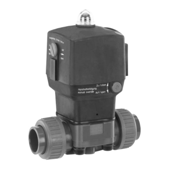
Manufacturer's information Functional description GEMÜ 600 / 630 is a plastic diaphragm Transport valve with a 2/2-way body. The valve has a piston actuator and an optical position Only transport the diaphragm valve by indicator as standard. "Normally closed suitable means. Do not drop. Handle (NC)", "Normally open (NO)"... -
Page 8: Installation And Connection
See chapter 6 "Technical data". 11.1 Installing the diaphragm valve WARNING The equipment is subject to pressure! Construction - GEMÜ 630 Risk of severe injury or death! Actuator size Code 1 ® Only work on depressurized plant. Actuator WARNING... - Page 9 6. Connect the other side of the valve 3. Allow butt weld spigots to cool down. body 2 to the piping 4, too. 4. Reassemble the valve body and the actuator with diaphragm (see chapter 12.4). 600, 630 29 / 44...
- Page 10 2. Connect the valve body to the piping. 5. Only use connector elements made of approved materials! Installation - Flare connection: 6. Tighten the bolts diagonally! 1. Also refer to GEMÜ FlareStar brochure ® and GEMÜ fl are and assembly instructions for preparation and connection of fl...
-
Page 11: Control Functions
Double acting (DA) 4: Control medium (close) For connectors 2 / 4 see pictures on the left 11.4 Optical position indicator Connector 2 GEMÜ 600 Connector 4 Valve open Valve closed Connector 2 The diaphragm valve is equipped with an optical position indicator. -
Page 12: Setting The Stroke Limiter
Set the toothed wheel 2 of the stroke limiter with a screwdriver as required. 11.6 Manual override GEMÜ 600 The diaphragm valve is equipped with a 12.1 Valve disassembly (removing manual override for control function 1 (NC). actuator from body) Only actuate the manual override in case 1. -
Page 13: Removing The Diaphragm
4. Replace damaged parts (only use described above. genuine parts from GEMÜ). 12.3 Mounting the diaphragm Diaphragm size 10 (only GEMÜ 630): The compressor is loose. Compressor and 12.3.1 General information actuator fl ange seen from below: Important: Compressor -... -
Page 14: General Information
Backing Diaphragm pin the recess of the compressor. diaphragm 6. If it is diffi cult to screw it in, check the thread, replace damaged parts (only use Diaphragm face Diaphragm boss genuine parts from GEMÜ). 600, 630 34 / 44... -
Page 15: Actuator Mounting On The Valve Body
Diaphragms degrade in the course retighten the bolts 18 (see chapter of time. After valve installation 20 "Sectional drawings and spare and commissioning you must parts"). retighten the bolts 18 (see chapter 20 "Sectional drawings and spare parts"). 600, 630 35 / 44... -
Page 16: Inspection And Servicing
Returns must be made with a completed by improper handling or third-party declaration of return. actions. If not completed, GEMÜ cannot process In case of doubt, contact GEMÜ before credits or commissioning. repair work 1. Use appropriate protective gear as but will dispose of the goods at the specifi... -
Page 17: Troubleshooting / Fault Clearance
Connect control medium Valve doesn't open or doesn't open fully Valve diaphragm incorrectly Remove actuator, check diaphragm mounted mounting, replace if necessary GEMÜ 600: Stroke limiter ** Reset stroke limiter incorrectly set Actuator spring faulty Replace actuator (for control function NO) - Page 18 Sectional drawings and spare parts GEMÜ 600 Optical position indicator Connector 4 / vent hole for c.f. 1 (NC) Connector 2 / vent hole for c.f. 2 (NO) Leak detection hole Item Name Order description Valve body O-ring K 600...
- Page 19 Leak detection hole Item Name Order description Valve body Actuator size 1: O-ring K 610... diaphragm size 10 Actuator size 2-4: Insert K 600... from diaphragm size 25 Union nut Diaphragm 600...M Bolt 630...S30 Washer Actuator 9630... 600, 630 39 / 44...