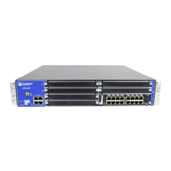
Juniper SRX650 Hardware Manual
Services gateway
Hide thumbs
Also See for SRX650:
- Hardware manual (182 pages) ,
- Quick start (4 pages) ,
- Installing (2 pages)

Related Manuals for Juniper SRX650


Summary of Contents for Juniper SRX650
- Page 1 SRX650 Services Gateway Hardware Guide Modified: 2018-07-05 Copyright © 2018, Juniper Networks, Inc.
- Page 2 END USER LICENSE AGREEMENT The Juniper Networks product that is the subject of this technical documentation consists of (or is intended for use with) Juniper Networks software. Use of such software is subject to the terms and conditions of the End User License Agreement (“EULA”) posted at https://www.juniper.net/support/eula/.
-
Page 3: Table Of Contents
SRX650 Services Gateway Front Panel ........18... - Page 4 Required Tools and Parts for Unpacking the SRX650 Services Gateway ..65 Unpacking the SRX650 Services Gateway ....... 65 Verifying Parts Received with the SRX650 Services Gateway .
- Page 5 SRX650 Services Gateway Grounding Specifications ..... . 81 Grounding the SRX650 Services Gateway ....... 82 Chapter 17 Connecting the SRX650 Services Gateway to External Devices .
- Page 6 Gateway ............136 Resetting the SRX650 Services Gateway ....... 136...
- Page 7 Agency Approvals and Regulatory Compliance Information ... . 197 SRX650 Services Gateway Agency Approvals ......197 SRX650 Services Gateway Acoustic Noise Compliance Statements .
- Page 8 SRX650 Services Gateway Hardware Guide viii Copyright © 2018, Juniper Networks, Inc.
- Page 9 Chassis Description ..........17 Figure 2: SRX650 Services Gateway Front Panel ......18 Figure 3: SRX650 Services Gateway Slot Numbers .
- Page 10 SRX650 Services Gateway Hardware Guide Figure 22: Connecting to the Console Port on the SRX650 Services Gateway . . 104 Part 5 Replacing Components Chapter 23 Replacing the Services and Routing Engine (SRE) Module ... . . 143 Figure 23: Removing the Services and Routing Engine (SRE) .
- Page 11 Table 3: Software Features and Licenses ....... . . 5 Table 4: SRX650 Services Gateway PoE Specifications ..... 9 Chapter 2 Hardware Component Overview .
- Page 12 Chapter 16 Grounding the SRX650 Services Gateway ......81 Table 23: Grounding Cable Specifications for the SRX650 Services Gateway . . . 82 Chapter 17 Connecting the SRX650 Services Gateway to External Devices .
-
Page 13: About The Documentation
® To obtain the most current version of all Juniper Networks technical documentation, see the product documentation page on the Juniper Networks website at https://www.juniper.net/documentation/ If the information in the latest release notes differs from the information in the documentation, follow the product Release Notes. -
Page 14: Table 1: Notice Icons
SRX650 Services Gateway Hardware Guide Table 1: Notice Icons Icon Meaning Description Informational note Indicates important features or instructions. Caution Indicates a situation that might result in loss of data or hardware damage. Warning Alerts you to the risk of personal injury or death. -
Page 15: Documentation Feedback
We encourage you to provide feedback, comments, and suggestions so that we can improve the documentation. You can provide feedback by using either of the following methods: Online feedback rating system—On any page of the Juniper Networks TechLibrary site , simply click the stars to rate the https://www.juniper.net/documentation/index.html content, and use the pop-up form to provide us with information about your experience. -
Page 16: Requesting Technical Support
7 days a week, 365 days a year. Self-Help Online Tools and Resources For quick and easy problem resolution, Juniper Networks has designed an online self-service portal called the Customer Support Center (CSC) that provides you with the following features: Find CSC offerings: https://www.juniper.net/customers/support/... - Page 17 About the Documentation For international or direct-dial options in countries without toll-free numbers, see https://www.juniper.net/support/requesting-support.html Copyright © 2018, Juniper Networks, Inc. xvii...
- Page 18 SRX650 Services Gateway Hardware Guide xviii Copyright © 2018, Juniper Networks, Inc.
-
Page 19: Overview
Overview Introduction on page 3 Hardware Component Overview on page 11 Chassis Description on page 17 Interface Module Description on page 27 Cooling System Description on page 31 Power System Description on page 33 Copyright © 2018, Juniper Networks, Inc. - Page 20 SRX650 Services Gateway Hardware Guide Copyright © 2018, Juniper Networks, Inc.
-
Page 21: Introduction
The services gateway provides cost-effective, scalable integration of routing, security, and other mid-range applications for these sites. The SRX650 Services Gateway has a modular 2U chassis that fits a 19-inch rack with a depth of approximately 18.1 inches. It contains a rear-pluggable Services and Routing Engine (SRE) module that provides robust performance for mid-range applications, particularly routing and security services. -
Page 22: Srx650 Services Gateway Software Features And Licenses
SRX650 Services Gateway Description on page 3 Documentation Accessing the SRX650 Services Gateway on page 10 SRX650 Services Gateway Software Features and Licenses on page 4 SRX650 Services Gateway Chassis on page 17 SRX650 Services Gateway Software Features and Licenses... -
Page 23: Table 3: Software Features And Licenses
Virtual private LAN service (VPLS) Multicast VLAN NOTE: MPLS is available in both packet-based mode and selective packet mode. Internet IPv4 protocols IPv6 routing and forwarding IP address Static addresses management Dynamic Host Configuration Protocol (DHCP) 8 Copyright © 2018, Juniper Networks, Inc. - Page 24 SRX650 Services Gateway Hardware Guide Table 3: Software Features and Licenses (continued) Feature Category Feature Encapsulation Ethernet: Media access control (MAC) encapsulation 802.1p tagging Point-to-Point Protocol over Ethernet (PPPoE) Circuit cross-connect (CCC) Translational cross-connect (TCC) Synchronous Point-to-Point Protocol (PPP) Frame Relay High-Level Data Link Control (HDLC) 802.1Q filtering and forwarding...
- Page 25 Junos OS command-line interface (CLI)—For services gateway configuration and management through the console through Telnet, or SSH Simple Network Management Protocol version 1 (SNMPv1), SNMPv2, and SNMPv3 Network and Security Manager (NSM) J-Flow flow monitoring and accounting Copyright © 2018, Juniper Networks, Inc.
-
Page 26: Srx650 Services Gateway Power Over Ethernet Overview
Commit scripts Operation scripts Event policies Hot-swappable GPIMs and XPIMs are hot-swappable on the SRX650 Services Gateway. Bypass ports LAN bypass ports are not supported on the SRX Series Services Gateways. Related SRX650 Services Gateway Description on page 3... -
Page 27: Table 4: Srx650 Services Gateway Poe Specifications
Voice over IP (VoIP) and IP phones and wireless access points. The PoE ports for the SRX650 Services Gateway reside on the individual XPIMs. The SRX650 Services Gateway supports the following XPIMs with PoE:... -
Page 28: Accessing The Srx650 Services Gateway
SRX650 Services Gateway Hardware Guide Related SRX650 Services Gateway Gigabit-Backplane Physical Interface Modules on page 27 Documentation SRX650 Services Gateway Power Supply on page 33 SRX650 Services Gateway Back Panel on page 24 Accessing the SRX650 Services Gateway You can use two user interfaces to monitor, configure, troubleshoot, and manage the... -
Page 29: Hardware Component Overview
Hardware Component Overview SRX650 Services Gateway Services and Routing Engine 6 on page 11 SRX650 Services Gateway Boot Devices and Dual-Root Partitioning Scheme on page 14 SRX650 Services Gateway Services and Routing Engine 6 The Services and Routing Engine (SRE) module provides processing power for security... -
Page 30: Figure 1: Services And Routing Engine
SRX650 Services Gateway Hardware Guide Figure 1: Services and Routing Engine SRE 6 Services and Routing Engine 6 USB 0 USB 1 OFFLINE RESET CONFIG CF ACT ALARM POWER STATUS COMPACT FLASH CONSOLE Table 5 on page 12 provides information about the SRE components. -
Page 31: Hardware Component Overview
Off indicates SRE high availability is not enabled. AUX port NOTE: The Auxiliary port is not supported on the SRX650 Services Gateway. CONSOLE port Connects a laptop to the services gateway for CLI management. The port uses an RJ-45 serial connection, is configured as data terminal equipment (DTE), and supports the RS-232 (EIA) standard. -
Page 32: Scheme
Installing the SRE on the SRX650 Services Gateway on page 75 SRX650 Services Gateway Back Panel on page 24 SRX650 Services Gateway Boot Devices and Dual-Root Partitioning Scheme The SRX650 Services Gateway can boot from the following storage media (in order of priority): Internal CompactFlash card (default; always present) - Page 33 When the SRX650 Services Gateway powers up, it tries to boot the Junos OS from the default storage media. If the device fails to boot from the default storage media, it tries to boot from the alternate storage media.
- Page 34 SRX650 Services Gateway Hardware Guide Copyright © 2018, Juniper Networks, Inc.
-
Page 35: Chassis Description
SRX650 Services Gateway Front Panel on page 18 SRX650 Services Gateway Back Panel on page 24 SRX650 Services Gateway Chassis The SRX650 Services Gateway chassis is a rigid sheet metal structure that houses all the other hardware components. Table 6 on page 17 provides information about the physical specifications for the services gateway. -
Page 36: Srx650 Services Gateway Front Panel
Grounding the SRX650 Services Gateway on page 82 SRX650 Services Gateway General Safety Guidelines and Warnings on page 165 SRX650 Services Gateway Front Panel The front panel of the SRX650 Services Gateway includes the following components: Front panel LEDs Electrostatic discharge (ESD) wrist strap outlet... -
Page 37: Table 7: Srx650 Services Gateway Front Panel Components
Figure 3 on page Table 7 on page 19 provides information about the front panel components of the services gateway. Table 7: SRX650 Services Gateway Front Panel Components Number Component Location Description Mounting brackets... - Page 38 SRX650 Services Gateway Hardware Guide Table 7: SRX650 Services Gateway Front Panel Components (continued) Number Component Location Description SRE/ACE LED 1.0 Left side of the The SRE/ACE 1.0 LED has the front chassis panel following indicator colors: Green and steadily on indicates: SRE1 is functioning normally.
- Page 39 Chapter 3: Chassis Description Table 7: SRX650 Services Gateway Front Panel Components (continued) Number Component Location Description 8 GPIM slots: Left side of the All slots support GPIMs. front chassis panel Slots 2 and 6 support XPIMs. GPIM slots 1 through...
- Page 40 SRX650 Services Gateway Hardware Guide Table 7: SRX650 Services Gateway Front Panel Components (continued) Number Component Location Description HA SYS LED Left side of the The High Availability (HA SYS) LED front chassis panel has the following indicator colors: Green and steadily on indicates that all configured HA links are available.
- Page 41 Chapter 3: Chassis Description Table 7: SRX650 Services Gateway Front Panel Components (continued) Number Component Location Description SRE/ACE LED 1.1 Left side of the The SRE/ACE 1.1 LED has the front chassis panel following indicator colors: Green and steadily on indicates ACE 1.1 half slot is functioning...
-
Page 42: Srx650 Services Gateway Back Panel
SRX650 Services Gateway Back Panel on page 24 SRX650 Services Gateway Services and Routing Engine 6 on page 11 SRX650 Services Gateway Back Panel The back panel of the SRX650 Services Gateway consists of the following components: Two power supply slots SRE slot... -
Page 43: Table 8: Srx650 Services Gateway Back Panel Components
Chapter 3: Chassis Description Table 8: SRX650 Services Gateway Back Panel Components Number Component Location Description Usage 2 power supply Left side of The power supply Power supplies are slots. Each power back panel provides power to the hot-swappable and... - Page 44 SRX650 Services Gateway Hardware Guide Table 8: SRX650 Services Gateway Back Panel Components (continued) Number Component Location Description Usage Fan tray (built-in Right of the Contains four 80 mm Cools the services component) back panel fans. gateway and its components. The fan tray is hot-swappable.
-
Page 45: Interface Module Description
1 to 4, or the top four slots 5 to 8. Figure 5 on page 28 shows how the slots on the front panel of the SRX650 Services Gateway are numbered. Copyright © 2018, Juniper Networks, Inc. -
Page 46: Figure 5: Srx650 Services Gateway Slot Numbers
Since the services gateway GPIMs communicate with the backplane at various performance levels, you must install them in the correct slots. Related SRX650 Services Gateway Front Panel on page 18 Documentation SRX650 Services Gateway Power over Ethernet Overview on page 8 Copyright © 2018, Juniper Networks, Inc. -
Page 47: Interface Module Description
Chapter 4: Interface Module Description Installing a Double-High, Double-Wide Gigabit-Backplane Physical Interface Module on the SRX Series Services Gateway Interface Modules Reference for Branch SRX Series Copyright © 2018, Juniper Networks, Inc. - Page 48 SRX650 Services Gateway Hardware Guide Copyright © 2018, Juniper Networks, Inc.
-
Page 49: Cooling System Description
SRX650 Services Gateway Cooling System on page 31 SRX650 Services Gateway Cooling System The fan controller is the cooling system component provided in the SRX650 Services Gateway to keep all components within the acceptable temperature range. The services gateway has a single fan tray that contains four 80 mm fans. - Page 50 SRX650 Services Gateway Hardware Guide Copyright © 2018, Juniper Networks, Inc.
-
Page 51: Power System Description
SRX650 Services Gateway Power Supply on page 33 SRX650 Services Gateway Power Supply The SRX650 Services Gateway uses either one AC or one DC power supply unit (PSU). The services gateway is equipped with one AC power supply (see Figure 9 on page 33). -
Page 52: Figure 10: Single Dc Power Supply For The Srx650 Services Gateway
SRX650 Services Gateway Hardware Guide Figure 10: Single DC Power Supply for the SRX650 Services Gateway The power supplies produce and distribute different output voltages to the services gateway components according to their voltage requirements. The available power supply components are listed in... -
Page 53: Power System Description
SRX650 Services Gateway Front Panel on page 18 SRX650 Services Gateway Back Panel on page 24 SRX650 Services Gateway Cooling System on page 31 Troubleshooting the Power System on the SRX650 Services Gateway on page 132 Copyright © 2018, Juniper Networks, Inc. - Page 54 SRX650 Services Gateway Hardware Guide Copyright © 2018, Juniper Networks, Inc.
-
Page 55: Site Planning And Specifications
Site Planning and Specifications Planning and Preparing the Site on page 39 Rack Requirements on page 43 Cabinet Requirements on page 51 Power Requirements and Specifications on page 53 Cable Specifications and Pinouts on page 59 Copyright © 2018, Juniper Networks, Inc. - Page 56 SRX650 Services Gateway Hardware Guide Copyright © 2018, Juniper Networks, Inc.
-
Page 57: Planning And Preparing The Site
Planning and Preparing the Site Site Preparation Checklist for the SRX650 Services Gateway on page 39 General Site Installation Guidelines for the SRX650 Services Gateway on page 41 SRX650 Services Gateway Environmental Specifications on page 42 Site Preparation Checklist for the SRX650 Services Gateway... -
Page 58: Table 10: Site Preparation Checklist For Srx650 Services Gateway
SRX650 Services Gateway Hardware Guide Table 10: Site Preparation Checklist for SRX650 Services Gateway Installation (continued) Performed Item or Task Additional Information Date Notes Verify that “SRX650 Services environmental Gateway Environmental factors such Specifications” on page 42 temperature and humidity... -
Page 59: General Site Installation Guidelines For The Srx650 Services Gateway
Documentation Installation Overview for the SRX650 Services Gateway on page 63 General Site Installation Guidelines for the SRX650 Services Gateway on page 41 General Site Installation Guidelines for the SRX650 Services Gateway The following precautions help you plan an acceptable operating environment for your... -
Page 60: Srx650 Services Gateway Environmental Specifications
SRX650 Services Gateway Chassis on page 17 Documentation SRX650 Services Gateway Cabinet Size and Clearance Requirements on page 51 SRX650 Services Gateway Rack Size and Strength Requirements on page 47 Clearance Requirements for Airflow and Hardware Maintenance of the SRX650 Services... -
Page 61: Rack Requirements
Rack-Mounting Requirements and Warnings on page 43 SRX650 Services Gateway Rack Size and Strength Requirements on page 47 SRX650 Services Gateway Spacing of Mounting Bracket and Flange Holes on page 47 Clearance Requirements for Airflow and Hardware Maintenance of the SRX650 Services... - Page 62 Les directives ci-dessous sont destinées à assurer la protection du personnel: Le rack sur lequel est monté le Juniper Networks services gateway doit être fixé à la structure du bâtiment. Si cette unité constitue la seule unité montée en casier, elle doit être placée dans le bas.
-
Page 63: Rack Requirements
Le seguenti direttive vengono fornite per garantire la sicurezza personale: Il Juniper Networks services gateway deve essere installato in un telaio, il quale deve essere fissato alla struttura dell'edificio. Questa unità deve venire montata sul fondo del supporto, se si tratta dell'unica unità... - Page 64 Om ställningen är försedd med stabiliseringsdon skall dessa monteras fast innan enheten installeras eller underhålls på ställningen. Related SRX650 Services Gateway General Safety Guidelines and Warnings on page 165 Documentation Copyright © 2018, Juniper Networks, Inc.
-
Page 65: Srx650 Services Gateway Rack Size And Strength Requirements
SRX650 Services Gateway Cabinet Size and Clearance Requirements on page 51 Site Preparation Checklist for the SRX650 Services Gateway on page 39 SRX650 Services Gateway Spacing of Mounting Bracket and Flange Holes on page 47 Connecting the SRX650 Services Gateway to the Building Structure on page 69... -
Page 66: Clearance Requirements For Airflow And Hardware Maintenance Of The Srx650 Services Gateway
Clearance Requirements for Airflow and Hardware Maintenance of the SRX650 Services Gateway When planning the installation site for the SRX650 Services Gateway, you need to allow sufficient clearance around the rack. When planning the installation site for the services gateway, consider the following: For the cooling system to function properly, the airflow around the chassis must be unrestricted. -
Page 67: Figure 11: Airflow Through The Chassis
Site Preparation Checklist for the SRX650 Services Gateway on page 39 SRX650 Services Gateway Rack Size and Strength Requirements on page 47 General Site Installation Guidelines for the SRX650 Services Gateway on page 41 Copyright © 2018, Juniper Networks, Inc. - Page 68 SRX650 Services Gateway Hardware Guide Copyright © 2018, Juniper Networks, Inc.
-
Page 69: Cabinet Requirements
SRX650 Services Gateway Cabinet Airflow Requirements on page 52 SRX650 Services Gateway Cabinet Size and Clearance Requirements You can install the SRX650 Services Gateway in a 19 in (48.3 cm) cabinet as defined in Cabinets, Racks, Panels, and Associated Equipment (document number EIA-310-D) published by the Electronic Industries Alliance ( http://www.ecaus.org/eia/site/index.html... -
Page 70: Srx650 Services Gateway Cabinet Airflow Requirements
Gateway on page 48 SRX650 Services Gateway Cabinet Airflow Requirements When you mount the SRX650 Services Gateway in a cabinet, you must ensure that ventilation through the cabinet is sufficient to prevent overheating. Consider the following when planning for chassis cooling: Ensure that the cool air supply you provide through the cabinet can adequately dissipate the thermal output of the services gateway. -
Page 71: Power Requirements And Specifications
SRX650 Services Gateway Electrical Wiring Guidelines on page 53 SRX650 Services Gateway Supported AC Power Cords on page 54 SRX650 Services Gateway DC Power Supply Electrical Specifications on page 56 SRX650 Services Gateway AC Power Supply Electrical Specifications on page 56... -
Page 72: Srx650 Services Gateway Supported Ac Power Cords
SRX650 Services Gateway Hardware Guide Table 13: Site Electrical Wiring Guidelines for the SRX650 Services Gateway (continued) Site Wiring Factor Guideline Radio frequency To reduce or eliminate the emission of RFI from your site wiring: interference (RFI) Use twisted-pair cable with a good distribution of grounding conductors. -
Page 73: Power Requirements And Specifications
Related SRX650 Services Gateway Power Supply on page 33 Documentation Clearance Requirements for Airflow and Hardware Maintenance of the SRX650 Services Gateway on page 48 SRX650 Services Gateway Electrical Wiring Guidelines on page 53 Site Preparation Checklist for the SRX650 Services Gateway on page 39... -
Page 74: Srx650 Services Gateway Dc Power Supply Electrical Specifications
SRX650 Services Gateway Hardware Guide SRX650 Services Gateway DC Power Supply Electrical Specifications The DC power supply electrical specifications for the SRX650 Services Gateway are listed in Table 15 on page Table 15: DC Power Supply Electrical Specifications for the SRX650 Services Gateway... -
Page 75: Srx650 Services Gateway Dc Power Cable Specifications
Related SRX650 Services Gateway Power Supply on page 33 Documentation Clearance Requirements for Airflow and Hardware Maintenance of the SRX650 Services Gateway on page 48 SRX650 Services Gateway Electrical Wiring Guidelines on page 53 Site Preparation Checklist for the SRX650 Services Gateway on page 39... -
Page 76: Srx650 Services Gateway Power Requirements
SRX650 Services Gateway Hardware Guide SRX650 Services Gateway Power Requirements The electrical and power requirements for the SRX650 Services Gateway provide information about the factors you must consider while planning the electrical wiring and power availability at your site. These requirements cover the following areas:... -
Page 77: Cable Specifications And Pinouts
Interface Cabling and Wiring Specifications for the SRX650 Services Gateway on page 59 RJ-45 Connector Pinouts for the SRX650 Services Gateway Ethernet Port on page 59 RJ-45 Connector Pinouts for the SRX650 Services Gateway Console Port on page 60 Interface Cabling and Wiring Specifications for the SRX650 Services Gateway The network interfaces supported on the services gateway accept different kinds of network cables. -
Page 78: Rj-45 Connector Pinouts For The Srx650 Services Gateway Console Port
Termination network Termination network RJ-45 Connector Pinouts for the SRX650 Services Gateway Console Port The port on the front panel labeled CONSOLE is an autosensing 10/100-Mbps Ethernet RJ-45 receptacle that accepts an RJ-45 cable for connecting the services gateway to a management LAN (or other device that supports out-of-band management). -
Page 79: Initial Installation And Configuration
Installing the Services Gateway on page 71 Grounding the SRX650 Services Gateway on page 81 Connecting the SRX650 Services Gateway to External Devices on page 85 Providing Power to the SRX650 Services Gateway on page 91 Performing Initial Configuration on page 97... - Page 80 SRX650 Services Gateway Hardware Guide Copyright © 2018, Juniper Networks, Inc.
-
Page 81: Installation Overview
Installation Overview Installation Overview for the SRX650 Services Gateway on page 63 Required Tools and Parts for Installing the SRX650 Services Gateway on page 63 SRX650 Services Gateway Autoinstallation Overview on page 64 Installation Overview for the SRX650 Services Gateway After you have prepared the site for installation and unpacked the SRX650 Services Gateway, you are ready to install the device. -
Page 82: Srx650 Services Gateway Autoinstallation Overview
Installation Overview for the SRX650 Services Gateway on page 63 Documentation Required Tools and Parts for Installing the SRX650 Services Gateway on page 63 Grounding the SRX650 Services Gateway on page 82 SRX650 Services Gateway Software Configuration Overview on page 97... -
Page 83: Unpacking The Services Gateway
Installation Overview for the SRX650 Services Gateway on page 63 Unpacking the SRX650 Services Gateway The SRX650 Services Gateway is shipped in a cardboard carton and secured with foam packing material. The carton also contains an accessory box and quick start instructions. -
Page 84: Verifying Parts Received With The Srx650 Services Gateway
Save the shipping carton and packing materials in case you need to move or ship the services gateway at a later time. Related Required Tools and Parts for Unpacking the SRX650 Services Gateway on page 65 Documentation Preparing the SRX650 Services Gateway for Rack-Mount Installation on page 69... -
Page 85: Table 21: Parts List For A Fully Configured Srx650 Services Gateway
Component Quantity 2U SRX650 Services Gateway chassis with 8 GPIM slots, 1 SRE slot, and 1 multi-use processor slot; 2 power supply slots; 1 fan tray with fans; and 4 10/100/1000 base-T ports. Includes blank covers for GPIM (8 covers for GPIM slots), SRE, multi-use processor, and power supply slots. - Page 86 SRX650 Services Gateway Hardware Guide Related Required Tools and Parts for Unpacking the SRX650 Services Gateway on page 65 Documentation Preparing the SRX650 Services Gateway for Rack-Mount Installation on page 69 Unpacking the SRX650 Services Gateway on page 65 Copyright © 2018, Juniper Networks, Inc.
-
Page 87: Installing The Mounting Hardware
Installation Overview for the SRX650 Services Gateway on page 63 Connecting the SRX650 Services Gateway to the Building Structure Always secure the rack in which you are installing the SRX650 Services Gateway to the structure of the building. If your geographical area is subject to earthquakes, bolt the rack to the floor. - Page 88 SRX650 Services Gateway Rack Size and Strength Requirements on page 47 Site Preparation Checklist for the SRX650 Services Gateway on page 39 SRX650 Services Gateway Spacing of Mounting Bracket and Flange Holes on page 47 Copyright © 2018, Juniper Networks, Inc.
-
Page 89: Installing The Services Gateway
Installing the Air Filter on the SRX650 Services Gateway on page 74 Installing the SRE on the SRX650 Services Gateway on page 75 Installing an AC Power Supply on the SRX650 Services Gateway on page 77 Installing a DC Power Supply on the SRX650 Services Gateway on page 78... -
Page 90: Installing The Srx650 Services Gateway In A Rack
171 Installing the SRX650 Services Gateway in a Rack You can front-mount the SRX650 Services Gateway in a rack. The mounting brackets are an optional accessory. Many types of racks are acceptable, including four-post (telco) racks, enclosed cabinets, and open-frame racks. -
Page 91: Installing The Fan Tray On The Srx650 Services Gateway
Chapter 15: Installing the Services Gateway SRX650 Services Gateway Spacing of Mounting Bracket and Flange Holes on page 47 Installing the Fan Tray on the SRX650 Services Gateway To install the fan tray, perform the following steps: Attach an electrostatic discharge (ESD) grounding strap to your bare wrist and connect the strap to one of the ESD points on the chassis. -
Page 92: Installing The Air Filter On The Srx650 Services Gateway
SRX650 Services Gateway Hardware Guide Installing the Air Filter on the SRX650 Services Gateway To install the air filter: Attach an electrostatic discharge (ESD) grounding strap to your bare wrist and connect the strap to one of the ESD points on the chassis. For more information about ESD, “Preventing Electrostatic Discharge Damage to the SRX650 Services Gateway”... -
Page 93: Installing The Sre On The Srx650 Services Gateway
Chapter 15: Installing the Services Gateway Figure 15: Tightening Captive Screws Related Removing the Air Filter on the SRX650 Services Gateway on page 152 Documentation Required Tools and Parts for Replacing Hardware Components on the SRX650 Services Gateway on page 141... -
Page 94: Figure 16: Installing The Services And Routing Engine (Sre)
SRX650 Services Gateway Back Panel on page 24 Documentation Removing the SRE from the SRX650 Services Gateway on page 143 SRX650 Services Gateway Services and Routing Engine 6 on page 11 Powering On the SRX650 Services Gateway on page 94... -
Page 95: Installing An Ac Power Supply On The Srx650 Services Gateway
Figure 17: Installing an AC Power Supply on the SRX650 Services Gateway Related Removing an AC Power Supply from the SRX650 Services Gateway on page 145 Documentation Connecting an AC Power Cord to the SRX650 Services Gateway on page 92... -
Page 96: Installing A Dc Power Supply On The Srx650 Services Gateway
Orient the power supply so that the locking lever is on the left as shown in Figure 18 on page Figure 18: Installing a DC Power Supply on an SRX650 Services Gateway Using both hands, slide the power supply straight into the chassis until the power supply is fully seated in the chassis slot. - Page 97 If more than one power supply is being installed, turn on all power supplies at the same time. Related Required Tools and Parts for Replacing Hardware Components on the SRX650 Services Documentation Gateway on page 141 Copyright © 2018, Juniper Networks, Inc.
- Page 98 SRX650 Services Gateway Hardware Guide Removing a DC Power Supply on the SRX650 Services Gateway on page 147 Removing a DC Power Supply Cable from the SRX650 Services Gateway on page 148 Copyright © 2018, Juniper Networks, Inc.
-
Page 99: Grounding The Srx650 Services Gateway
CHAPTER 16 Grounding the SRX650 Services Gateway Required Tools and Parts for Grounding, Powering On, and Powering Off the SRX650 Services Gateway on page 81 SRX650 Services Gateway Grounding Specifications on page 81 Grounding the SRX650 Services Gateway on page 82... -
Page 100: Grounding The Srx650 Services Gateway
Grounding the SRX650 Services Gateway on page 82 Documentation Connecting the SRX650 Services Gateway to the AC Power Supply on page 91 Powering On the SRX650 Services Gateway on page 94 Powering Off the SRX650 Services Gateway on page 95... - Page 101 Powering On the SRX650 Services Gateway on page 94 Documentation Powering Off the SRX650 Services Gateway on page 95 Required Tools and Parts for Grounding, Powering On, and Powering Off the SRX650 Services Gateway on page 81 SRX650 Services Gateway General Safety Guidelines and Warnings on page 165...
- Page 102 SRX650 Services Gateway Hardware Guide Copyright © 2018, Juniper Networks, Inc.
-
Page 103: Connecting The Srx650 Services Gateway To External Devices
Connecting the Modem to the Console Port on the SRX650 Services Gateway on page 86 Connecting the CLI at the User End for the SRX650 Services Gateway on page 87 Connecting the Modem at the SRX650 Services Gateway End on page 88... -
Page 104: Figure 19: Console Cable Connector
Connecting to the SRX650 Services Gateway from the CLI Remotely on page 106 Documentation Connecting the Modem at the SRX650 Services Gateway End on page 88 Connecting the CLI at the User End for the SRX650 Services Gateway on page 87 Copyright © 2018, Juniper Networks, Inc. -
Page 105: Connecting The Cli At The User End For The Srx650 Services Gateway
Chapter 17: Connecting the SRX650 Services Gateway to External Devices Connecting the CLI at the User End for the SRX650 Services Gateway To connect to the CLI through a dial-up modem connected to the console port on the SRX650 Services Gateway: Connect a modem at your remote location to a management device. -
Page 106: Connecting The Modem At The Srx650 Services Gateway End
Connecting the Modem at the SRX650 Services Gateway End Before you can connect a dial-up modem to the console port on the SRX650 Services Gateway, you must configure the modem to accept a call on the first ring and to accept DTR signals. - Page 107 Connecting to the SRX650 Services Gateway from the CLI Remotely on page 106 Documentation Connecting the Modem to the Console Port on the SRX650 Services Gateway on page 86 Connecting the CLI at the User End for the SRX650 Services Gateway on page 87 Copyright © 2018, Juniper Networks, Inc.
- Page 108 SRX650 Services Gateway Hardware Guide Copyright © 2018, Juniper Networks, Inc.
-
Page 109: Providing Power To The Srx650 Services Gateway
Do not mix AC and DC power supplies within the same services gateway. Damage to the device might occur. The 645 W AC power supply with PoE support is available for the SRX650 Services Gateway. You connect AC power to the services gateway by attaching the power cord from the AC power source to the AC appliance inlet located on the power supply. -
Page 110: Connecting An Ac Power Cord To The Srx650 Services Gateway
168 Grounding the SRX650 Services Gateway on page 82 Organizing Interface Cables on the SRX650 Services Gateway on page 85 SRX650 Services Gateway General Safety Guidelines and Warnings on page 165 Connecting an AC Power Cord to the SRX650 Services Gateway... -
Page 111: Connecting The Srx650 Services Gateway To The Dc Power Supply
CAUTION: Do not mix AC and DC power supplies within the same services gateway. Damage to the device might occur. The 645 W DC power supply with PoE support is available for the SRX650 Services Gateway. WARNING: Before performing the following procedure, ensure that power is removed from the DC circuit. -
Page 112: Powering On The Srx650 Services Gateway
Documentation page 168 Grounding the SRX650 Services Gateway on page 82 Organizing Interface Cables on the SRX650 Services Gateway on page 85 SRX650 Services Gateway General Safety Guidelines and Warnings on page 165 Powering On the SRX650 Services Gateway To power on the services gateway: Ensure that you have connected the power supply to the device. -
Page 113: Powering Off The Srx650 Services Gateway
Chapter 18: Providing Power to the SRX650 Services Gateway Insert the plug of the power supply adapter into an AC or DC power source receptacle. a. Using AC Power supply—Insert the appliance coupler end of the power cord into the appliance inlet on the power supply and the power cord plug into an external AC power source receptacle. - Page 114 SRX650 Services Gateway Hardware Guide NOTE: Forced shutdown is not supported on the SRX650 Services Gateway. After powering off a power supply, wait at least 60 seconds before turning it back on. After powering on a power supply, wait at least 10 seconds before turning it off.
-
Page 115: Performing Initial Configuration
Connecting to the SRX650 Services Gateway from the CLI Remotely on page 106 Viewing Factory-Default Settings of the SRX650 Services Gateway on page 106 Configuring Basic Settings for the SRX650 Services Gateway with the CLI or the J-Web Interface on page 113... -
Page 116: Srx650 Services Gateway Basic Settings
Documentation Connecting to the SRX650 Services Gateway Setup Wizard on page 100 Connecting to the SRX650 Services Gateway from the CLI Locally on page 104 Connecting to the SRX650 Services Gateway from the CLI Remotely on page 106 SRX650 Services Gateway Basic Settings Table 27 on page 99 provides information on basic connectivity settings. -
Page 117: Performing Initial Configuration
Boston or Azores NOTE: For Common Criteria compliance, you must configure NTP to provide accurate timestamps for system log messages. For more information, see the Configuration Guides for Junos OS Public Sector Certifications Copyright © 2018, Juniper Networks, Inc. -
Page 118: Connecting To The Srx650 Services Gateway Setup Wizard
Connecting to the SRX650 Services Gateway from the CLI Remotely on page 106 Connecting to the SRX650 Services Gateway Setup Wizard If you plan to use the setup wizard to configure the SRX650 Services Gateway, you must connect through the built-in Ethernet port 0/1 as shown in Figure 20 on page 100. -
Page 119: Figure 21: Ethernet Cable Connector (Rj-45)
The upper left area of the wizard page shows where you are in the setup process. Click a field in the wizard page to display information about that field in the lower left area of the page. Copyright © 2018, Juniper Networks, Inc. -
Page 120: Srx650 Services Gateway Secure Web Access Overview
Performing Initial Software Configuration on the SRX650 Services Gateway Using the Documentation Setup Wizard Connecting to the SRX650 Services Gateway from the CLI Locally on page 104 Connecting to the SRX650 Services Gateway from the CLI Remotely on page 106 SRX650 Services Gateway Secure Web Access Overview You can manage a services gateway remotely through the J-Web interface. -
Page 121: Srx650 Services Gateway Secure Cli Access Overview
Interface on page 113 SRX650 Services Gateway Secure CLI Access Overview Telnet allows you to connect to the SRX650 Services Gateway and access the CLI to execute commands from a remote system. Telnet connections are not encrypted and therefore can be intercepted. -
Page 122: Connecting To The Srx650 Services Gateway From The Cli Locally
SRX650 Services Gateway Software Configuration Overview on page 97 Connecting to the SRX650 Services Gateway from the CLI Locally If you plan to use the CLI to configure the SRX650 Services Gateway, you must connect through the console port, as shown in Figure 22 on page 104. -
Page 123: Table 28: Port Settings
None Stop bits Flow control None Power on the services gateway by pressing the Power button on the front of the services gateway. Verify that the POWER LED on the front panel turns green. Copyright © 2018, Juniper Networks, Inc. -
Page 124: Connecting To The Srx650 Services Gateway From The Cli Remotely
Connecting to the SRX650 Services Gateway from the CLI Remotely on page 106 Connecting to the SRX650 Services Gateway from the CLI Remotely You can connect an SRX650 Services Gateway to the CLI from a remote location through two dial-up modems:... - Page 125 SRX240 Services Gateway. % vi srx240-poe-16xge-factory.conf The following sample output displays the factory-default configuration on an SRX240 Services Gateway: ## $Id: $ ## Copyright (c) 2009, Juniper Networks, Inc. ## All rights reserved. Copyright © 2018, Juniper Networks, Inc.
- Page 126 SRX650 Services Gateway Hardware Guide system { autoinstallation { delete-upon-commit; traceoptions { level verbose; flag { all; interfaces { ge-0/0/0 { bootp; services { ssh; telnet; dhcp { router { 192.168.1.1; pool 192.168.1.0/24 { address-range low 192.168.1.2 high 192.168.1.254; propagate-settings ge-0/0/0.0;...
- Page 127 0 { family ethernet-switching { vlan { members vlan-trust; ge-0/0/6 { unit 0 { family ethernet-switching { vlan { members vlan-trust; ge-0/0/7 { unit 0 { family ethernet-switching { vlan { members vlan-trust; Copyright © 2018, Juniper Networks, Inc.
- Page 128 SRX650 Services Gateway Hardware Guide ge-0/0/8 { unit 0 { family ethernet-switching { vlan { members vlan-trust; ge-0/0/9 { unit 0 { family ethernet-switching { vlan { members vlan-trust; ge-0/0/10 { unit 0 { family ethernet-switching { vlan { members vlan-trust;...
- Page 129 { from zone trust; to zone untrust; rule source-nat-rule { match { source-address 0.0.0.0/0; then { source-nat { interface; screen { ids-option untrust-screen { icmp { ping-death; ip { source-route-option; tear-drop; tcp { Copyright © 2018, Juniper Networks, Inc.
- Page 130 SRX650 Services Gateway Hardware Guide syn-flood { alarm-threshold 1024; attack-threshold 200; source-threshold 1024; destination-threshold 2048; timeout 20; land; zones { security-zone trust { host-inbound-traffic { system-services { all; protocols { all; interfaces { vlan.0; security-zone untrust { interfaces { ge-0/0/0.0 {...
-
Page 131: J-Web Interface
Documentation SRX650 Services Gateway Software Configuration Overview on page 97 Configuring Basic Settings for the SRX650 Services Gateway with the CLI or the J-Web Interface on page 113 Configuring Basic Settings for the SRX650 Services Gateway with the CLI or the J-Web... -
Page 132: Gateway
SRX650 Services Gateway Hardware Guide Table 30: Configuring Basic Settings Required or Using the J-Web Setup Task Optional Wizard Using the CLI Navigate to Required After establishing basic Navigate to the top of Configure System: connectivity and entering root the configuration Identification page. - Page 133 J-Web Preferences Preferences page, from the page appears J-Web commit options, before the specify when you want Configure System: commit to occur. Time page in the wizard. Specify when you want commit to occur. Copyright © 2018, Juniper Networks, Inc.
- Page 134 SRX650 Services Gateway Software Configuration Overview on page 97 Documentation Connecting to the SRX650 Services Gateway from the CLI Locally on page 104 Connecting to the SRX650 Services Gateway from the CLI Remotely on page 106 Connecting to the SRX650 Services Gateway Setup Wizard on page 100...
- Page 135 Chapter 19: Performing Initial Configuration Displaying Basic Connectivity Configurations for the SRX650 Services Gateway To verify that the SRX650 Services Gateway has the settings you configured, you should display the basic connectivity configurations. Because the basic connectivity settings appear in different places in the configuration hierarchy, displaying the entire configuration at once makes viewing the settings easier.
-
Page 136: Built-In Ethernet Ports For The Srx650 Services Gateway
Documentation Performing Initial Software Configuration on the SRX650 Services Gateway Using the Setup Wizard Configuring Basic Settings for the SRX650 Services Gateway with the CLI or the J-Web Interface on page 113 Built-In Ethernet Ports for the SRX650 Services Gateway... -
Page 137: Table 32: Security Policies
DHCP server. Therefore, to continue using the services gateway as a management interface, you should configure the IP address of the interface as part of the initial configuration. Copyright © 2018, Juniper Networks, Inc. - Page 138 Connecting to the SRX650 Services Gateway Setup Wizard on page 100 Documentation Connecting to the SRX650 Services Gateway from the CLI Locally on page 104 Connecting to the SRX650 Services Gateway from the CLI Remotely on page 106 SRX650 Services Gateway Software Configuration Overview on page 97...
-
Page 139: Maintaining And Troubleshooting Components
PART 4 Maintaining and Troubleshooting Components Maintaining Components on page 123 Troubleshooting Components on page 125 Copyright © 2018, Juniper Networks, Inc. - Page 140 SRX650 Services Gateway Hardware Guide Copyright © 2018, Juniper Networks, Inc.
-
Page 141: Maintaining Components
CHAPTER 20 Maintaining Components Required Tools and Parts for Maintaining the SRX650 Services Gateway Hardware Components on page 123 Routine Maintenance Procedures for the SRX650 Services Gateway on page 123 Maintaining the SRX650 Services Gateway Cooling System Components on page 124... -
Page 142: Maintaining The Srx650 Services Gateway Cooling System Components
SRX650 Services Gateway Hardware Guide Related Required Tools and Parts for Maintaining the SRX650 Services Gateway Hardware Documentation Components on page 123 Maintaining the SRX650 Services Gateway Cooling System Components on page 124 Maintaining the SRX650 Services Gateway Power Supply on page 124... -
Page 143: Troubleshooting Components
Gateway on page 129 Troubleshooting the Power System on the SRX650 Services Gateway on page 132 Using the RESET CONFIG Button on the SRX650 Services Gateway on page 135 Changing the RESET CONFIG Button Behavior on the SRX650 Services Gateway on page 136... -
Page 144: Troubleshooting With Leds On The Srx650 Services Gateway
SRX650 Services Gateway Hardware Guide Troubleshooting with LEDs on the SRX650 Services Gateway The LEDs available on the services gateway display the status of various components. Table 34 on page 126describes the LEDs on the chassis. To view LED information on the Services and Routing Engine (SRE), see “SRX650 Services Gateway Services and Routing... - Page 145 In this situation performance might be reduced, current bandwidth could cause packet drops, or single point of failure might now exist. Off indicates that chassis cluster is not enabled. Copyright © 2018, Juniper Networks, Inc.
- Page 146 SRX650 Services Gateway Hardware Guide Table 34: Component LEDs on the Services Gateway Chassis (continued) Location Usage SRE 0 Left side of the front chassis The SRE 0 LED has the following panel indicator colors: Green and steadily on indicates SRE0 is functioning normally.
-
Page 147: Troubleshooting With Chassis And Interface Alarm Messages On The Srx650 Services Gateway
Gateway on page 129 Troubleshooting the Power System on the SRX650 Services Gateway on page 132 Using the RESET CONFIG Button on the SRX650 Services Gateway on page 135 Changing the RESET CONFIG Button Behavior on the SRX650 Services Gateway on... -
Page 148: Table 35: Alarms For Services Gateway Chassis Components
SRX650 Services Gateway Hardware Guide Examples: user@host# run show chassis alarms 4 alarms currently active Alarm time Class Description 2009-02-05 09:27:11 PDT Major ge-0/0/5: Link down 2009-02-05 09:27:11 PDT Major ge-0/0/6: Link down user@host> show chassis fpc Temp CPU Utilization (%) - Page 149 SRX650 Services Gateway Back Panel on page 24 Troubleshooting the Power System on the SRX650 Services Gateway on page 132 Using the RESET CONFIG Button on the SRX650 Services Gateway on page 135 Changing the RESET CONFIG Button Behavior on the SRX650 Services Gateway on page 136 Copyright ©...
-
Page 150: Troubleshooting The Power System On The Srx650 Services Gateway
SRX650 Services Gateway Hardware Guide Troubleshooting the Power System on the SRX650 Services Gateway The LEDs on the services gateway enable you to determine the performance and operation of the power system. The POWER LED located on the front panel of the services gateway,... - Page 151 The Junos OS also can shut down one of the power supplies for other reasons. In this case, the remaining power supplies provide power to the services gateway, and you can still view the system status through the CLI. Copyright © 2018, Juniper Networks, Inc.
-
Page 152: Table 37: Power Supply Faceplate Leds
The DC input power provided to the power supply is outside of tolerance. Unlit The power supply is not receiving input power. Related Troubleshooting with the CLI on the SRX650 Services Gateway on page 125 Documentation Copyright © 2018, Juniper Networks, Inc. -
Page 153: Using The Reset Config Button On The Srx650 Services Gateway
106. For details about performing initial software configuration, see “Configuring Basic Settings for the SRX650 Services Gateway with the CLI or the J-Web Interface” on page 113. Related Changing the RESET CONFIG Button Behavior on the SRX650 Services Gateway on... -
Page 154: Changing The Reset Config Button Behavior On The Srx650 Services
Documentation Troubleshooting with the CLI on the SRX650 Services Gateway on page 125 Using the RESET CONFIG Button on the SRX650 Services Gateway on page 135 SRX650 Services Gateway Front Panel on page 18 Troubleshooting the Power System on the SRX650 Services Gateway on page 132... - Page 155 Related Grounding the SRX650 Services Gateway on page 82 Documentation Powering On the SRX650 Services Gateway on page 94 Powering Off the SRX650 Services Gateway on page 95 SRX650 Services Gateway Front Panel on page 18 Copyright © 2018, Juniper Networks, Inc.
- Page 156 SRX650 Services Gateway Hardware Guide Copyright © 2018, Juniper Networks, Inc.
-
Page 157: Replacing Components
Replacing the Services and Routing Engine (SRE) Module on page 143 Replacing Power System Components on page 145 Replacing Cooling System Components on page 151 Contacting Customer Support and Returning Components on page 155 Copyright © 2018, Juniper Networks, Inc. - Page 158 SRX650 Services Gateway Hardware Guide Copyright © 2018, Juniper Networks, Inc.
-
Page 159: Overview Of Replacing Components
CHAPTER 22 Overview of Replacing Components Required Tools and Parts for Replacing Hardware Components on the SRX650 Services Gateway on page 141 Required Tools and Parts for Replacing Hardware Components on the SRX650 Services Gateway To replace hardware components, you need the tools and parts listed in Table 38 on page 141. - Page 160 Removing the SRE from the SRX650 Services Gateway on page 143 Removing the Air Filter on the SRX650 Services Gateway on page 152 Removing an AC Power Supply from the SRX650 Services Gateway on page 145 Removing a DC Power Supply on the SRX650 Services Gateway on page 147...
-
Page 161: Replacing The Services And Routing Engine (Sre) Module
Replacing the Services and Routing Engine (SRE) Module Removing the SRE from the SRX650 Services Gateway on page 143 Removing the SRE from the SRX650 Services Gateway The SRE is located at the back panel of the chassis and can be installed in the horizontal slots labeled SRE0 or SRE1.0/1.1. -
Page 162: Figure 23: Removing The Services And Routing Engine (Sre)
SRX650 Services Gateway Back Panel on page 24 Documentation Installing the SRE on the SRX650 Services Gateway on page 75 SRX650 Services Gateway Services and Routing Engine 6 on page 11 Powering Off the SRX650 Services Gateway on page 95... -
Page 163: Replacing Power System Components
Disconnecting an AC Power Cord from the SRX650 Services Gateway on page 146 Removing a DC Power Supply on the SRX650 Services Gateway on page 147 Removing a DC Power Supply Cable from the SRX650 Services Gateway on page 148 Removing an AC Power Supply from the SRX650 Services Gateway Up to two power supplies can be located at the rear of the chassis on the right side. -
Page 164: Disconnecting An Ac Power Cord From The Srx650 Services Gateway
SRX650 Services Gateway Hardware Guide Figure 24: Removing an AC Power Supply from the SRX650 Services Gateway Related Installing an AC Power Supply on the SRX650 Services Gateway on page 77 Documentation Required Tools and Parts for Replacing Hardware Components on the SRX650 Services... -
Page 165: Removing A Dc Power Supply On The Srx650 Services Gateway
Chapter 24: Replacing Power System Components Removing a DC Power Supply on the SRX650 Services Gateway Up to two power supplies can be located at the rear of the chassis on the right side. Each DC power supply weighs approximately 2 lbs, 13.4 oz (1.29 kg). -
Page 166: Removing A Dc Power Supply Cable From The Srx650 Services Gateway
Gateway on page 141 Installing a DC Power Supply on the SRX650 Services Gateway on page 78 Removing a DC Power Supply Cable from the SRX650 Services Gateway on page 148 Removing a DC Power Supply Cable from the SRX650 Services Gateway... - Page 167 Required Tools and Parts for Replacing Hardware Components on the SRX650 Services Documentation Gateway on page 141 Removing a DC Power Supply on the SRX650 Services Gateway on page 147 Installing a DC Power Supply on the SRX650 Services Gateway on page 78 Copyright © 2018, Juniper Networks, Inc.
- Page 168 SRX650 Services Gateway Hardware Guide Copyright © 2018, Juniper Networks, Inc.
-
Page 169: Replacing Cooling System Components
CHAPTER 25 Replacing Cooling System Components Removing the Fan Tray on the SRX650 Services Gateway on page 151 Removing the Air Filter on the SRX650 Services Gateway on page 152 Removing the Fan Tray on the SRX650 Services Gateway A single handle with two screws holds both the fan tray and air filter on the back of the services gateway. -
Page 170: Removing The Air Filter On The Srx650 Services Gateway
Gateway on page 141 Removing the Air Filter on the SRX650 Services Gateway NOTE: The SRX650 Services Gateway does not ship with an air filter. An air filter must be purchased separately. CAUTION: Except during replacement, always keep the air filter in place while the services gateway is operating. -
Page 171: Replacing Cooling System Components
Attach an electrostatic discharge (ESD) grounding strap to your bare wrist and connect the strap to one of the ESD points on the chassis. For more information about ESD, “Preventing Electrostatic Discharge Damage to the SRX650 Services Gateway” on page 168. -
Page 172: Figure 28: Removing The Air Filter
SRX650 Services Gateway Hardware Guide Figure 28: Removing the Air Filter Related Installing the Air Filter on the SRX650 Services Gateway on page 74 Documentation Required Tools and Parts for Replacing Hardware Components on the SRX650 Services Gateway on page 141... -
Page 173: Contacting Customer Support And Returning Components
Contacting Customer Support Once you have located the serial numbers of the device or component, you can return the device or component for repair or replacement. For this, you need to contact Juniper Networks Technical Assistance Center (JTAC). You can contact JTAC 24 hours a day, 7 days a week, using any of the following methods: On the Web: Using the Case Manager link at https://www.juniper.net/support/... -
Page 174: Return Procedure For The Srx650 Services Gateway
Packing the SRX650 Services Gateway Components for Shipment on page 160 Return Procedure for the SRX650 Services Gateway To return an SRX650 Services Gateway or component to Juniper Networks for repair or replacement: Determine the part number and serial number of the services gateway or component. -
Page 175: Labels
Chapter 26: Contacting Customer Support and Returning Components Locating the SRX650 Services Gateway Chassis Serial Number and Agency Labels The SRX650 Services Gateway serial number is located on the bottom of the device on the compliance/agency label. Related Return Procedure for the SRX650 Services Gateway on page 156... -
Page 176: Information You Might Need To Supply To Jtac
Contacting Customer Support on page 155 Required Tools and Parts for Packing the SRX650 Services Gateway To remove the components from the SRX650 Services Gateway or to remove the services gateway from a rack, you need the following tools and parts:... -
Page 177: Packing The Srx650 Services Gateway For Shipment
To pack the SRX650 Services Gateway for shipment: Retrieve the shipping carton and packing materials in which the services gateway was originally shipped. If you do not have these materials, contact your Juniper Networks representative about approved packaging materials. Attach an electrostatic discharge (ESD) grounding strap to your bare wrist and connect the strap to the ESD point on the chassis or to an outside ESD point if the device is disconnected from earth ground. -
Page 178: Packing The Srx650 Services Gateway Components For Shipment
Documentation Packing the SRX650 Services Gateway Components for Shipment on page 160 Required Tools and Parts for Packing the SRX650 Services Gateway on page 158 Packing the SRX650 Services Gateway Components for Shipment Follow these guidelines for packing and shipping individual components of the services... -
Page 179: Safety
Laser and LED Safety Guidelines and Warnings on page 173 Maintenance and Operational Safety Guidelines and Warnings on page 179 Electrical Safety Guidelines and Warnings on page 187 Agency Approvals and Regulatory Compliance Information on page 197 Copyright © 2018, Juniper Networks, Inc. - Page 180 SRX650 Services Gateway Hardware Guide Copyright © 2018, Juniper Networks, Inc.
-
Page 181: General Safety Guidelines And Warnings
CHAPTER 27 General Safety Guidelines and Warnings SRX650 Services Gateway Definition of Safety Warning Levels on page 163 SRX650 Services Gateway General Safety Guidelines and Warnings on page 165 SRX650 Services Gateway Safety Requirements, Warnings, and Guidelines on page 166... - Page 182 Innan du utför arbete på någon utrustning måste du vara medveten om farorna med elkretsar och känna till vanligt förfarande för att förebygga skador. Related SRX650 Services Gateway General Safety Guidelines and Warnings on page 165 Documentation Copyright © 2018, Juniper Networks, Inc.
-
Page 183: Srx650 Services Gateway General Safety Guidelines And Warnings
Avoid touching uninsulated electrical wires or terminals that have not been disconnected from their power source. Such an action could cause electrical shock. Related SRX650 Services Gateway Definition of Safety Warning Levels on page 163 Documentation Preventing Electrostatic Discharge Damage to the SRX650 Services Gateway on... -
Page 184: Srx650 Services Gateway Safety Requirements, Warnings, And Guidelines
Documentation SRX650 Services Gateway Electrical Wiring Guidelines on page 53 Required Tools and Parts for Installing the SRX650 Services Gateway on page 63 Preparing the SRX650 Services Gateway for Rack-Mount Installation on page 69 General Site Installation Guidelines for the SRX650 Services Gateway on page 41... -
Page 185: Qualified Personnel Warning
Related SRX650 Services Gateway General Safety Guidelines and Warnings on page 165 Documentation Qualified Personnel Warning on page 167 Qualified Personnel Warning... -
Page 186: Preventing Electrostatic Discharge Damage To The Srx650 Services
Varning! Denna utrustning ska endast installeras och bytas ut av utbildad och kvalificerad personal. Related SRX650 Services Gateway General Safety Guidelines and Warnings on page 165 Documentation Restricted Access Area Warning on page 166 Preventing Electrostatic Discharge Damage to the SRX650 Services Gateway Many services gateway hardware components are sensitive to damage from static electricity. -
Page 187: Figure 29: Placing A Component Into An Electrostatic Bag
169. If you are returning a component, place it into an electrostatic bag before packing it. Figure 29: Placing a Component into an Electrostatic Bag Related SRX650 Services Gateway Definition of Safety Warning Levels on page 163 Documentation SRX650 Services Gateway Fire Safety Requirements and Fire Suppression Equipment on page 171 SRX650 Services Gateway General Safety Guidelines and Warnings on page 165 Copyright ©... - Page 188 SRX650 Services Gateway Hardware Guide Copyright © 2018, Juniper Networks, Inc.
-
Page 189: Fire Safety Requirements
SRX650 Services Gateway Fire Safety Requirements and Fire Suppression Equipment on page 171 SRX650 Services Gateway Fire Safety Requirements and Fire Suppression Equipment In the event of a fire emergency involving devices and other network equipment, the safety of people is the primary concern. Establish procedures for protecting people in the event of a fire emergency, provide safety training, and properly provision fire control equipment and fire extinguishers. - Page 190 To keep warranties effective, do not use a dry chemical fire extinguisher to control a fire at or near a Juniper Networks services gateway. If a dry chemical fire extinguisher is used, the unit is no longer eligible for coverage under a service agreement.
-
Page 191: Laser And Led Safety Guidelines And Warnings
Related SRX650 Services Gateway General Safety Guidelines and Warnings on page 165 Documentation Class 1 Laser Warning on page 174 Class 1 LED Product Warning on page 174... -
Page 192: Class 1 Laser Warning
Aviso Produto laser de classe 1. ¡Atención! Producto láser Clase I. Varning! Laserprodukt av klass 1. Related SRX650 Services Gateway General Safety Guidelines and Warnings on page 165 Documentation General Laser Safety Guidelines on page 173 Class 1 LED Product Warning on page 174... -
Page 193: Laser Beam Warning
¡Atención! Aviso sobre producto LED de Clase 1. Varning! Lysdiodprodukt av klass 1. Related SRX650 Services Gateway General Safety Guidelines and Warnings on page 165 Documentation General Laser Safety Guidelines on page 173 Class 1 Laser Warning on page 174... -
Page 194: Radiation From Open Port Apertures Warning
Varning! Osynlig strålning kan avges från en portöppning utan ansluten fiberkabel och du bör därför undvika att bli utsatt för strålning genom att inte stirra in i oskyddade öppningar. Related SRX650 Services Gateway General Safety Guidelines and Warnings on page 165 Documentation Copyright © 2018, Juniper Networks, Inc. - Page 195 Chapter 29: Laser and LED Safety Guidelines and Warnings General Laser Safety Guidelines on page 173 Class 1 Laser Warning on page 174 Class 1 LED Product Warning on page 174 Laser Beam Warning on page 175 Copyright © 2018, Juniper Networks, Inc.
- Page 196 SRX650 Services Gateway Hardware Guide Copyright © 2018, Juniper Networks, Inc.
-
Page 197: Maintenance And Operational Safety Guidelines And Warnings
Warnung Bei Einsetzen einer falschen Batterie besteht Explosionsgefahr. Ersetzen Sie die Batterie nur durch den gleichen oder vom Hersteller empfohlenen Batterietyp. Entsorgen Sie die benutzten Batterien nach den Anweisungen des Herstellers. Copyright © 2018, Juniper Networks, Inc. -
Page 198: Lightning Activity Warning
Följ tillverkarens anvisningar vid kassering av använda batterier. Related SRX650 Services Gateway General Safety Guidelines and Warnings on page 165 Documentation Jewelry Removal Warning on page 181 Lightning Activity Warning on page 180... -
Page 199: Jewelry Removal Warning
Varning! Vid åska skall du aldrig utföra arbete på systemet eller ansluta eller koppla loss kablar. Related SRX650 Services Gateway General Safety Guidelines and Warnings on page 165 Documentation Battery-Handling Warning on page 179 Jewelry Removal Warning on page 181... - Page 200 Related SRX650 Services Gateway General Safety Guidelines and Warnings on page 165 Documentation Battery-Handling Warning on page 179 Lightning Activity Warning on page 180...
-
Page 201: Operating Temperature Warning
C). To prevent airflow restriction, allow at least 6 in. (15.2 cm) of clearance around the ventilation openings. Waarschuwing Om te voorkomen dat welke services gateway van de Juniper Networks services gateway dan ook oververhit raakt, dient u deze niet te bedienen op een plaats waar de maximale aanbevolen ο... -
Page 202: Product Disposal Warning
15,2 cm omkring ventilationsöppningarna. Related SRX650 Services Gateway General Safety Guidelines and Warnings on page 165 Documentation Battery-Handling Warning on page 179 Lightning Activity Warning on page 180... -
Page 203: Lithium Battery
Varning! Slutlig kassering av denna produkt bör skötas i enlighet med landets alla lagar och föreskrifter. Related SRX650 Services Gateway General Safety Guidelines and Warnings on page 165 Documentation Battery-Handling Warning on page 179 Lightning Activity Warning on page 180... - Page 204 SRX650 Services Gateway Hardware Guide Copyright © 2018, Juniper Networks, Inc.
-
Page 205: Electrical Safety Guidelines And Warnings
If possible, send another person to get medical aid. Otherwise, assess the condition of the victim, then call for help. Related SRX650 Services Gateway General Safety Guidelines and Warnings on page 165 Documentation General Electrical Safety Guidelines and Warnings on page 187... -
Page 206: Ac Power Electrical Safety Guidelines
Related SRX650 Services Gateway General Safety Guidelines and Warnings on page 165 Documentation In Case of Electrical Accident on page 187... -
Page 207: Dc Power Electrical Safety Guidelines
The attached power cable is only for this product. Do not use the cable for another product. Related SRX650 Services Gateway General Safety Guidelines and Warnings on page 165 Documentation In Case of Electrical Accident on page 187 General Electrical Safety Guidelines and Warnings on page 187... - Page 208 SRX650 Services Gateway Hardware Guide DC Power Electrical Safety Guidelines The following electrical safety guidelines apply to a DC-powered services gateway: A DC-powered services gateway is equipped with a DC terminal block that is rated for the power requirements of a maximally configured services gateway. To supply sufficient power, terminate the DC input wiring on a facility DC source capable of supplying at least 65 A @ –48 VDC for the system, or at least 48 A @ –48 VDC for...
- Page 209 ¡Atención! Antes de proceder con los siguientes pasos, comprobar que la alimentación del circuito de corriente continua (CC) esté cortada (OFF). Para asegurarse de que toda la alimentación esté cortada (OFF), localizar el Copyright © 2018, Juniper Networks, Inc.
- Page 210 SRX650 Services Gateway Hardware Guide interruptor automático en el panel que alimenta al circuito de corriente continua, cambiar el interruptor automático a la posición de Apagado (OFF), y sujetar con cinta la palanca del interruptor automático en posición de Apagado (OFF).
- Page 211 –48 V a –48 V, +RTN a +RTN, entonces molió para moler. Observe que el alambre de tierra se debe conectar siempre primero y desconectar por último. Observe que el alambre de tierra se debe conectar siempre primero y desconectar por último. Copyright © 2018, Juniper Networks, Inc.
- Page 212 SRX650 Services Gateway Hardware Guide ¡Atención! Wire a fonte de alimentação de DC Usando os talões apropriados na extremidade da fiação. Ao conectar a potência, a seqüência apropriada da fiação é moída para moer, +RTN a +RTN, então –48 V a –48 V. Ao desconectar a potência, a seqüência apropriada da fiação é...
- Page 213 Storleken på dessa kontakter måste vara avpassad till ledningarna och måste kunna hålla både isoleringen och ledaren fastklämda. Related SRX650 Services Gateway General Safety Guidelines and Warnings on page 165 Documentation In Case of Electrical Accident on page 187 General Electrical Safety Guidelines and Warnings on page 187...
- Page 214 SRX650 Services Gateway Hardware Guide Copyright © 2018, Juniper Networks, Inc.
-
Page 215: Agency Approvals And Regulatory Compliance Information
CHAPTER 32 Agency Approvals and Regulatory Compliance Information SRX650 Services Gateway Agency Approvals on page 197 SRX650 Services Gateway Acoustic Noise Compliance Statements on page 198 Canada on page 198 European Community on page 199 Japan on page 199 United States on page 199... -
Page 216: Srx650 Services Gateway Acoustic Noise Compliance Statements
EN-61000-4-6 (2007) Immunity to Conducted Disturbances EN-61000-4-11 (2004) Voltage Dips and Sags Related SRX650 Services Gateway General Safety Guidelines and Warnings on page 165 Documentation SRX650 Services Gateway Acoustic Noise Compliance Statements on page 198 SRX650 Services Gateway Acoustic Noise Compliance Statements The maximum emitted sound pressure level is 70 dB(A) or less per EN ISO 7779. -
Page 217: European Community
This is a Class A product. In a domestic environment this product might cause radio interference in which case the user might be required to take adequate measures. Related SRX650 Services Gateway General Safety Guidelines and Warnings on page 165 Documentation Canada on page 198... - Page 218 SRX650 Services Gateway Hardware Guide Related SRX650 Services Gateway General Safety Guidelines and Warnings on page 165 Documentation Canada on page 198 European Community on page 199 Israel Japan on page 199 SRX650 Services Gateway Acoustic Noise Compliance Statements on page 198...