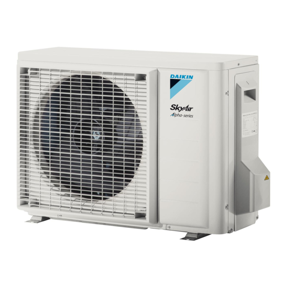
Daikin R32 split series Installation Manual
Hide thumbs
Also See for R32 split series:
- Installer's reference manual (120 pages) ,
- Operation manual (116 pages) ,
- User reference manual (52 pages)
Summary of Contents for Daikin R32 split series
- Page 1 Installation manual R32 split series RZAG35A2V1B Installation manual RZAG50A2V1B English R32 split series RZAG60A2V1B...
- Page 2 2P427092-16P...
- Page 3 2P427092-16P...
-
Page 4: Table Of Contents
To connect the refrigerant piping to the outdoor unit .. Daikin website (publicly accessible). Checking the refrigerant piping ..........▪ The full set of latest technical data is available on the Daikin 4.3.1 To check for leaks............extranet (authentication required). -
Page 5: Installation Site Requirements Of The Outdoor Unit
Provide at least 300 mm of free space below the unit. Additionally, make sure the unit is positioned at least 100 mm above the expected level of snow. 1 Use a drain plug for drainage. 2 Use a Ø16 mm hose (field supply). RZAG35~60A2V1B Installation manual R32 split series 3P548265-1 – 2018.08... -
Page 6: Connecting The Refrigerant Piping
2 Leave as is for 4-5 minutes and check the pressure: ▪ Piping length. Keep field piping as short as possible. ▪ Piping protection. Protect the field piping against physical damage. Installation manual RZAG35~60A2V1B R32 split series 3P548265-1 – 2018.08... -
Page 7: Charging Refrigerant
3 Vacuum drying on the outdoor unit's internal refrigerant piping is performed. NOTICE Before completely recharging, perform vacuum drying on the outdoor unit's internal refrigerant piping as well. RZAG35~60A2V1B Installation manual R32 split series 3P548265-1 – 2018.08... -
Page 8: To Determine The Complete Recharge Amount
DANGER: RISK OF ELECTROCUTION Multimeter (DC voltage range) S80 – reversing solenoid valve lead wire S20 – electronic expansion valve lead wire S40 – thermal overload relay lead wire S90 – thermistor lead wire Installation manual RZAG35~60A2V1B R32 split series 3P548265-1 – 2018.08... -
Page 9: Specifications Of Standard Wiring Components
The correct pipe size is installed and the pipes are Phillips screwdriver. properly insulated. 5 Install the switch box cover. The stop valves (gas and liquid) on the outdoor unit are fully open. RZAG35~60A2V1B Installation manual R32 split series 3P548265-1 – 2018.08... -
Page 10: Checklist During Commissioning
Supply voltage (for power saving). Power supply fault. Turn the power OFF and back ON, and check the LED within approximately 3 minutes. If the LED is ON again, the outdoor unit PCB is faulty. Installation manual RZAG35~60A2V1B R32 split series 3P548265-1 – 2018.08... -
Page 11: Technical Data
8 Technical data Technical data A subset of the latest technical data is available on the regional Daikin website (publicly accessible). The full set of latest technical data is available on the Daikin extranet (authentication required). Wiring diagram The wiring diagram is delivered with the unit, located inside of the outdoor unit (bottom side of the top plate). -
Page 12: Piping Diagram
Automatic reset ·9.5· CuT Field piping Accumulator ·9.5· CuT Accumulator Gas stop valve Compressor PED categories of equipment – High pressure switch: category IV; Compressor: category II; Other equipment: art. 4§3. Installation manual RZAG35~60A2V1B R32 split series 3P548265-1 – 2018.08... - Page 13 Automatic reset ·12.7· CuT Field piping Accumulator ·12.7· CuT Accumulator Gas stop valve Compressor PED categories of equipment – High pressure switch: category IV; Compressor: category II; Other equipment: art. 4§3. RZAG35~60A2V1B Installation manual R32 split series 3P548265-1 – 2018.08...
- Page 16 3P548265-1 2018.08...


