Yamaha RX-V1700 Owner's Manual
Yamaha av receiver owner's manual
Hide thumbs
Also See for RX-V1700:
- Owner's manual (791 pages) ,
- Service manual (163 pages) ,
- Firmware update manual (3 pages)
Table of Contents
Advertisement
Quick Links
Advertisement
Table of Contents

Related Manuals for Yamaha RX-V1700


Summary of Contents for Yamaha RX-V1700
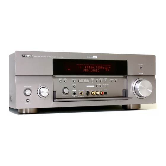
- Page 1 RX-V1700 AV Receiver OWNER’S MANUAL...
- Page 2 YAMAHA will not be held responsible for any damage resulting from use of this unit with a voltage other than specified.
-
Page 3: Table Of Contents
Connecting other components ... 22 Connecting a multi-format player or an external decoder ... 26 Connecting a YAMAHA iPod universal dock ... 27 Using the VIDEO AUX jacks on the front panel ... 27 Connecting the FM and AM antennas ... 28 Connecting the power cable... -
Page 4: Features
“iPod” is a trademark of Apple Computer, Inc., registered in the U.S. and other countries. FEATURES iPod controlling capability ◆ DOCK terminal to connect a YAMAHA iPod universal dock (such as the YDS-10, sold separately), which supports iPod (Click and Wheel), iPod nano, and iPod mini Other features ◆... -
Page 5: Getting Started
Supplied accessories Check that you received all of the following parts. Remote control POWER POWER STANDBY POWER AUDIO SEL SLEEP PHONO TUNER MULTI CH IN V-AUX/DOCK CBL/SAT MD/TAPE CD-R VCR 1 DVR/VCR 2 SELECT SOURCE TV VOL VOLUME – – –... -
Page 6: Controls And Functions
CONTROLS AND FUNCTIONS CONTROLS AND FUNCTIONS Front panel This section describes only the amplifier controls and functions of this unit. See the following pages for details about other control and functions. • AM/FM tuning ... see page 54 AUDIO SELECT INPUT MAIN ZONE ON/OFF... - Page 7 7 MULTI ZONE buttons ZONE 2 ON/OFF Turns on Zone 2 only or sets it to the standby mode. See page 107 for details. ZONE 3 ON/OFF Turns on Zone 3 only or sets it to the standby mode. See page 107 for details. Note These buttons are operational only when MASTER ON/OFF is pressed inward to the ON position.
-
Page 8: Remote Control
CONTROLS AND FUNCTIONS Remote control ■ Remote control controls and functions This section describes only the amplifier controls and functions of this unit. See the following pages for details about other control and functions. • AM/FM tuning ... see page 54 •... - Page 9 0 MACRO ON/OFF Turns on or off the macro function (see page 100). A MACRO Programs a series of operations to be controlled with a single button (see page 100). B STANDBY Sets the main zone to the standby mode (see page 31). Note This button is operational only when MASTER ON/OFF on the front panel is pressed inward to the ON position.
-
Page 10: Zone 2/Zone 3 Remote Control
CONTROLS AND FUNCTIONS Zone 2/Zone 3 remote control This section describes the function of each control on the Zone 2/Zone 3 remote control used to control the amplifier functions of Zone 2 or Zone 3. See the following pages for details about other controls and functions. -
Page 11: Preparing The Remote Control
Preparing the remote control ■ Installing batteries in the remote control Press the part and slide the battery compartment cover off. Insert the four supplied batteries (AAA, R03, UM-4) according to the polarity markings (+ and –) on the inside of the battery compartment. -
Page 12: Front Panel Display
HDMI IN 1 or HDMI IN 2 jacks (see page 19). 2 DOCK indicator Lights up when you station your iPod in a YAMAHA iPod universal dock (such as the YDS-10, sold separately) connected to the DOCK terminal of this unit (see page 27). - Page 13 0 DSP indicators The respective indicator lights up when any of the DSP sound field programs are selected. CINEMA DSP indicator Lights up when you select a CINEMA DSP sound field program (see page 45). HiFi DSP indicator Lights up when you select a HiFi DSP sound field program (see page 45).
-
Page 14: Rear Panel
CONTROLS AND FUNCTIONS Rear panel MONITOR OUT CBL/SAT (PLAY) TAPE REMOTE HDMI CENTER FRONT(6CH) PHONO CD-R IN 2 CBL/ (PLAY) OUT (REC) WOOFER SB(8CH) IN 1 AUDIO MULTI CH INPUT DOCK DVR/ VCR2 1 REMOTE jacks See page 106 for details. 2 COMPONENT VIDEO jacks See pages 21 and 22 for connection information. -
Page 15: Connections
1.8 m above the floor. Subwoofer (SW) The use of a subwoofer with a built-in amplifier, such as the YAMAHA Active Servo Processing Subwoofer System, is effective not only for reinforcing bass frequencies from any or all channels, but also for high... -
Page 16: Connecting Speakers
CONNECTIONS Connecting speakers Be sure to connect the left channel (L), right channel (R), “+” (red) and “–” (black) properly. If the connections are faulty, no sound will be heard from the speakers, and if the polarity of the speaker connections is incorrect, the sound will be unnatural and lack bass. -
Page 17: Connecting The Speaker Cable
Connect presence left and right speakers to these terminals. SUBWOOFER jack Connect a subwoofer with a built-in amplifier (such as the YAMAHA Active Servo Processing Subwoofer System) to this jack. ■ Connecting the speaker cable Remove approximately 10 mm of insulation... - Page 18 CONNECTIONS Hook the speaker terminal wrench onto the WRENCH HOLDER on the rear panel of this unit when not in use. ■ Connecting to the SP2 speaker terminals Connect Zone 2 or Zone 3 speakers to these terminals (see page 106). Open the tab.
-
Page 19: Using Bi-Amplification Connections
Using bi-amplification connections Some of the speakers have speaker wire connections that allow bi-amplification to enhance the performance of the speaker system. This unit allows you to make bi- amplification connection to one speaker system. Check if your speakers support bi-amplification. As these speakers are shipped to you, you will note shorting bars or bridges, one connecting the two red input terminals and the other connecting the two black input terminals. -
Page 20: Information On Jacks And Cable Plugs
CONNECTIONS Information on jacks and cable plugs Audio jacks and cable plugs DIGITAL AUDIO COAXIAL (White) (Red) (Orange) Left and right Coaxial analog audio digital audio cable plugs cable plug ■ Audio jacks This unit has three types of audio jacks. Connection depends on the availability of audio jacks on your other components. -
Page 21: Information On Hdmi
Information on HDMI This unit has the HDMI IN 1, HDMI IN 2 and HDMI OUT jacks for digital audio and video signal input/output. Connect the HDMI IN 1 or HDMI IN 2 jack of this unit to the HDMI output jack of other HDMI components (such as a DVD player). -
Page 22: Audio And Video Signal Flow
CONNECTIONS Audio and video signal flow ■ Audio signal flow Input HDMI DIGITAL AUDIO (COAXIAL) DIGITAL AUDIO (OPTICAL) AUDIO Digital output Analog output Notes • 2-channel as well as multi-channel PCM, Dolby Digital and DTS signals input at the HDMI IN 1 or HDMI IN 2 jack can be output at the HDMI OUT jack only when “SUPPORT AUDIO”... -
Page 23: Connecting A Tv Monitor Or Projector
Connecting a TV monitor or projector Connect your TV (or projector) to the HDMI OUT jack, the COMPONENT VIDEO MONITOR OUT jacks, the S VIDEO MONITOR OUT jack or the VIDEO MONITOR OUT jack of this unit. CAUTION Do not connect this unit or other components to the AC power supply until all connections between components are complete. -
Page 24: Connecting Other Components
CONNECTIONS Connecting other components CAUTION Do not connect this unit or other components to the AC power supply until all connections between components are complete. Notes • When “V CONV.” is set to “OFF” (see page 90), be sure to make the same type of video connections as those made for your TV (see page 21). - Page 25 ■ Connecting a DVD recorder, PVR or VCR Note When you connect another VCR to this unit, connect it to the VCR 1 terminals (S VIDEO IN, VIDEO IN, AUDIO IN, S VIDEO OUT, VIDEO OUT and AUDIO OUT jacks) same as DVR/VCR 2 terminals except the DIGITAL INPUT (COAXIAL) jack. ■...
-
Page 26: Connecting Audio Components
CONNECTIONS ■ Connecting audio components Notes • To make a digital connection to a component other than the default component assigned to either the DIGITAL INPUT jack or the DIGITAL OUTPUT jack, select the corresponding setting for “OPTICAL OUT”, “OPTICAL IN”, or “COAXIAL IN” in “I/O ASSIGNMENT”... -
Page 27: Connecting An External Amplifier
■ Connecting an external amplifier This unit has more than enough power for any home use. However, if you want to add more power to the speaker output or if you want to use another amplifier, connect an external amplifier to the PRE OUT jacks. Notes •... -
Page 28: Connecting A Multi-Format Player Or An External Decoder
CONNECTIONS Connecting a multi-format player or an external decoder This unit is equipped with 6 additional input jacks (left and right FRONT, CENTER, left and right SURROUND and SUBWOOFER) for discrete multi-channel input from a multi-format player, external decoder, sound processor or pre-amplifier. -
Page 29: Connecting A Yamaha Ipod Universal Dock
This unit is equipped with the DOCK terminal on the rear panel that allows you to connect a YAMAHA iPod universal dock (such as the YDS-10, sold separately) where you can station your iPod and control playback of your iPod using the supplied remote control. -
Page 30: Connecting The Fm And Am Antennas
• A properly installed outdoor antenna provides clearer reception than an indoor one. If you experience poor reception quality, install an outdoor antenna. Consult the nearest authorized YAMAHA dealer or service center about outdoor antennas. Indoor FM AM loop antenna... -
Page 31: Connecting The Power Cable
Connecting the power cable ■ Connecting the AC power cable CAUTION Use the supplied AC cable. Do not use other AC power cables as doing so may result in fire or electrical shock. Plug the supplied AC power cable into the AC inlet after all other connections are complete, then plug the AC power cable into an AC wall outlet. -
Page 32: Setting The Speaker Impedance
CONNECTIONS Setting the speaker impedance CAUTION If you are to use 6 ohm speakers, set “SPEAKER IMP.” to “6ΩMIN” as follows BEFORE using this unit. 4 ohm speakers can be also used as the front speakers. AUDIO TONE PRESET/ MEMORY TUNING SELECT CONTROL... -
Page 33: Turning On And Off The Power
Turning on and off the power When all connections are complete, turn on this unit. MAIN ZONE ON/OFF AUDIO TONE PRESET/ SELECT CONTROL A/B/C/D/E PRESET/TUNING EDIT INPUT STRAIGHT MAIN ZONE MULTI ZONE EFFECT YPAO SILENT CINEMA S VIDEO VIDEO ON/OFF PROGRAM OPTIMIZER PHONES... -
Page 34: Auto Setup
AUTO SETUP This unit employs the YPAO (YAMAHA Parametric Room Acoustic Optimizer) technology which lets you avoid troublesome listening-based speaker setup and achieves highly accurate sound adjustments automatically. The supplied optimizer microphone collects and this unit analyzes the sound your speakers produce in your actual listening environment. - Page 35 Make sure of the following check points before starting the AUTO SETUP operations. • Speakers are connected appropriately. • Supplied optimizer microphone is connected to this unit and placed appropriately. • Headphones are disconnected from this unit. • The room is sufficiently quiet. •...
- Page 36 AUTO SETUP Volume level LEVEL Checks and adjusts the volume level of each speaker. Choices: CHECK, SKIP • Select “CHECK” to automatically check and adjust this item. • Select “SKIP” to skip this item and perform no adjustments. Press n to select “START” and then press ENTER to start the setup procedure.
- Page 37 Press ENTER to display the setup results in detail. PRESET/CH ENTER A/B/C/D/E RESULT:EXIT . RESULT 5/4/0.1 DIST: 4.50/ 6.10m LVL : -9.0/ +6.5dB SET CANCEL [ ]/[ ]:Up/Down [ENTER]:Enter RESULT:WIRING FRONT L;;;;;;;OK [ ]/[ ]:Select [ENTER]:Return Press l / h repeatedly to toggle between the setup result displays.
- Page 38 AUTO SETUP Press ENTER to return to the top “RESULT:EXIT” display. PRESET/CH RESULT:EXIT . RESULT ENTER A/B/C/D/E [ ]/[ ]:Up/Down [ENTER]:Enter Make sure the pointer is pointing at “SET” and “CANCEL” and then press l / h to select “SET” or “CANCEL”. PRESET/CH RESULT:EXIT RESULT...
- Page 39 ■ If “WARNING” appears When this unit detects potential problems during the “AUTO SETUP” procedure, “WARNING” appears in the “RESULT:EXIT” display. Check the warning messages to correct your speaker settings. Note Warnings differ from errors in that warnings do not cancel the “AUTO SETUP”...
-
Page 40: Playback
PLAYBACK CAUTION Extreme caution should be exercised when you play back CDs encoded in DTS. If you play back a CD encoded in DTS on a DTS-incompatible CD player, you will only hear some unwanted noise that may damage your speakers. Check whether your CD player supports CDs encoded in DTS. Also, check the sound output level of your CD player before you play back a CD encoded in DTS. - Page 41 Start playback on the selected source component or select a broadcast station. • Refer to the operating instructions for the source component. • See page 54 for details about tuning instructions. Rotate VOLUME on the front panel (or press VOLUME +/– on the remote control) to adjust the volume to the desired output level.
-
Page 42: Selecting Audio Input Jacks (Audio Select)
PLAYBACK Selecting audio input jacks (AUDIO SELECT) This unit comes with a variety of input jacks. Use this feature (Audio input jack select) to switch the input jack assigned to an input source when more than one jacks are assigned to an input source. •... -
Page 43: Selecting The Multi Ch Input Component
Selecting the MULTI CH INPUT component Use this feature to select the component connected to the MULTI CH INPUT jacks (see page 26) as the input source. Rotate the input selector on the front panel to select MULTI CH INPUT (or MULTI CH IN on the remote control). -
Page 44: Displaying The Input Source Information
PLAYBACK Displaying the input source information You can display the format, sampling frequency, channel, bit rate and flag data of the current input signal. Set the operation mode selector to AMP and then press SET MENU on the remote control. The top “SET MENU”... -
Page 45: Playing Video Sources In The Background Of An Audio Source
Playing video sources in the background of an audio source You can combine a video image from a video source with sound from an audio source. For example, you can enjoy listening to classical music while viewing beautiful scenery from the video source on the video monitor. Press the input selector buttons on the remote control to select a video source and then an audio source. -
Page 46: Sound Field Programs
This unit is equipped with a variety of precise digital decoders that allow you to enjoy multi-channel playback from almost any stereo or multi-channel sound source. This unit is also equipped with a YAMAHA digital sound field processing (DSP) chip containing several sound field programs which you can use to enhance your playback experience. -
Page 47: Sound Field Program Descriptions
Sound field program descriptions Select a sound field program based on your listening preference, not merely on the name of the program, etc. Remote control Category of the button program MOVIE MOVIE This program clearly reproduces dialog and sound effects in the latest sound form for science fiction films, thus creating a broad and expansive cinematic space amid silence. - Page 48 SOUND FIELD PROGRAMS CLASSICAL CLASSICAL This program creates a relatively wide space with a high ceiling like an audience hall in a palace. It offers pleasant reverberations that are suitable for courtly music and chamber music. DSP LEVEL LIVENESS INIT. DLY REV.TIME LIVE/CLUB LIVE/CLUB...
- Page 49 ENTERTAIN ENTERTAINMENT This sound field has been optimized for action games such as car racing and FPS games. It uses the reflection data that limits the effects range per channel in order to offer a powerful playing environment with a being-there feeling by enhancing various effects tones while maintaining a clear sense of directions.
-
Page 50: Stereo Playback
SOUND FIELD PROGRAMS MOVIE MOVIE This program creates the extremely wide sound field of a 70-mm movie theater. It precisely reproduces the source sound in detail, making both the video and the sound field incredibly real. This is ideal for any kind of video source encoded with Dolby Surround, Dolby Digital or DTS (especially large-scale movie productions). -
Page 51: Enjoying Unprocessed Input Sources
■ Using sound field programs without surround speakers (Virtual CINEMA DSP) Virtual CINEMA DSP allows you to enjoy the CINEMA DSP programs without surround speakers. It creates virtual speakers to reproduce the natural sound field. When you set “SUR. L/R SP” NONE”... -
Page 52: Using Audio Features
USING AUDIO FEATURES Enjoying pure hi-fi sound Use the Pure Direct mode to enjoy the pure fidelity sound of the selected source. When the Pure Direct mode is activated, this unit plays back the selected source with the least circuitry. Press PURE DIRECT on the front panel (or on the remote control) to turn on or off the Pure Direct mode. -
Page 53: Adjusting The Speaker Level
Adjusting the speaker level You can adjust the output level of each speaker while listening to a music source. This is also possible when playing sources input at the MULTI CH INPUT jacks. Note This operation will override the level adjustments made in “AUTO SETUP”... -
Page 54: Selecting The Compressed Music Enhancer Mode
USING AUDIO FEATURES Selecting the Compressed Music Enhancer mode Compression artifacts (such as the MP3 format) are created by a lossy compression scheme where the audio is resampled to lower the bit rate and to remove sounds that are indistinguishable to typical human hearing. The Compressed Music Enhancer feature of this unit enhances your listening experience by regenerating the missing harmonics in a compression artifact. -
Page 55: Selecting The Night Listening Mode
Selecting the night listening mode The night listening modes are designed to improve listenability at lower volumes or at night. Choose either “NIGHT:CINEMA” or “NIGHT:MUSIC” depending on the type of material you are playing. Press NIGHT on the front panel (or set the operation mode selector to AMP and then press NIGHT on the remote control) repeatedly to select “NIGHT:CINEMA”... -
Page 56: Fm/Am Tuning
FM/AM TUNING There are 2 tuning methods: automatic and manual. Automatic tuning is effective when station signals are strong and there is no interference. If the signal from the station you want to select is weak, tune into it manually. You can also use the automatic and manual preset tuning features to store up to 40 stations (A1 to E8: 8 preset station numbers in each of the 5 preset station groups). -
Page 57: Remote Control Functions
■ Remote control functions Note Zone 2/Zone 3 remote control is supplied with U.S.A., Canada, Australia, U.K., China, Asia and General models only. POWER PHONO V-AUX/DOCK TV VOL TV MUTE LEVEL TITLE A/B/C/D/E RETURN CLASSICAL STEREO FREQ/TEXT DISC SKIP 1 TUNER Selects “TUNER”... -
Page 58: Automatic Tuning
FM/AM TUNING Automatic tuning Automatic tuning is effective when station signals are strong and there is no interference. AUDIO MEMORY TUNING TONE PRESET/ CONTROL FM/AM MAN'L/AUTO FM MODE SELECT A/B/C/D/E PRESET/TUNING EDIT INPUT STRAIGHT ZONE ON/OFF ZONE CONTROLS MAIN ZONE MULTI ZONE ZONE 3 EFFECT... -
Page 59: Manual Tuning
Manual tuning If the signal received from the station you want to select is weak, tune into it manually. Note Manually tuning into an FM station automatically switches the tuner to monaural reception to increase the signal quality. AUDIO MEMORY TUNING TONE PRESET/... -
Page 60: Automatic Preset Tuning
FM/AM TUNING Automatic preset tuning You can use the automatic preset tuning feature to store up to 40 FM stations with strong signals (A1 to E8: 8 preset station numbers in each of the 5 preset station groups) in order. You can then recall any preset station easily by selecting the preset station number. -
Page 61: Manual Preset Tuning
Manual preset tuning You can also store up to 40 stations (A1 to E8: 8 preset station numbers in each of the 5 preset station groups) manually. AUDIO MEMORY TUNING TONE PRESET/ SELECT CONTROL A/B/C/D/E PRESET/TUNING FM/AM MAN'L/AUTO FM MODE ENHANCER EDIT INPUT... -
Page 62: Selecting Preset Stations
FM/AM TUNING Selecting preset stations You can tune into any desired station simply by selecting the preset station group and number under which it was stored. AUDIO TONE PRESET/ MEMORY TUNING SELECT CONTROL A/B/C/D/E PRESET/TUNING FM/AM MAN'L/AUTO FM MODE EDIT INPUT STRAIGHT ZONE ON/OFF... -
Page 63: Exchanging Preset Stations
Exchanging preset stations You can exchange the assignments of two preset stations with each other. The example below describes the procedure to exchange preset station “E1” with “A5”. AUDIO TONE PRESET/ MEMORY TUNING SELECT CONTROL A/B/C/D/E PRESET/TUNING FM/AM MAN'L/AUTO FM MODE ENHANCER EDIT... -
Page 64: Radio Data System Tuning (U.k. And Europe Models Only)
RADIO DATA SYSTEM TUNING (U.K. AND EUROPE MODELS ONLY) RADIO DATA SYSTEM TUNING (U.K. AND EUROPE MODELS ONLY) Radio Data System is a data transmission system used by FM stations in many countries. This unit can receive various Radio Data System data such as PS (program service), PTY (program type), RT (radio text), CT (clock time), and EON (enhanced other networks) when receiving Radio Data System broadcasting stations. -
Page 65: Selecting The Radio Data System Program Type (Pty Seek Mode)
Selecting the Radio Data System program type (PTY SEEK mode) Use this feature to select the desired radio program by program type from the all preset Radio Data System broadcasting stations. Use the automatic preset tuning feature to preset Radio Data System broadcasting stations (see page 58). -
Page 66: Using The Enhanced Other Networks (Eon) Data Service
RADIO DATA SYSTEM TUNING (U.K. AND EUROPE MODELS ONLY) Press PTY SEEK START on the remote control to start searching for all the available Radio Data System preset stations. The name of the selected program type flashes and the PTY HOLD indicator lights up in the front panel display while this unit is searching for stations. - Page 67 Press EON on the remote control repeatedly to select one of the 4 Radio Data System program types (NEWS, AFFAIRS, INFO or SPORT). The name of the selected program type appears in the front panel display. • To cancel the EON feature, press EON on the remote control repeatedly until the name of the program type disappears and “EON OFF”...
-
Page 68: Using Ipod
AUDIO OUT (REC) jacks for recording. • Your iPod battery is automatically charged when your iPod is stationed in a YAMAHA iPod universal dock (such as the YDS-10, sold separately) connected to the DOCK terminal of this unit as long as this unit is turned on. You can also select whether this unit charges the battery of the stationed iPod or not when this unit is in the standby mode by selecting the “STANDBY CHRG”... - Page 69 Set the operation mode selector to SOURCE and then press DISPLAY on the remote control. The following display appears in the OSD. PARAMETER SOURCE DISPLAY iPod Playlists Artists Albums Songs Genres Composers Settings Press k / n / l / h on the remote control to navigate the iPod menu and then press ENTER to begin playback of the selected song.
-
Page 70: Recording
RECORDING Recording adjustments and other operations are performed from the recording components. Refer to the operating instructions for those components. CAUTION The DTS signal is a digital bitstream. Attempting to digitally record the DTS bitstream will result in noise being recorded. Therefore, if you want to use this unit to record sources encoded in DTS, the following considerations and adjustments need to be made. -
Page 71: Advanced Sound Configurations
ADVANCED SOUND CONFIGURATIONS Changing sound field parameter settings You can enjoy good quality sound with the initial factory settings. Although you do not have to change the initial factory settings, you can change some of the parameters to better suit the input source or your listening room. Note You cannot change the sound field parameter values when “MEMORY GUARD”... -
Page 72: Sound Field Parameter Descriptions
ADVANCED SOUND CONFIGURATIONS ■ Sound field parameter descriptions You can adjust the values of certain digital sound field parameters so that the sound fields are recreated accurately in your listening room. Not all of the following parameters are found in every program. To change sound field parameter settings to suit your listening environment, see page 69 for details. - Page 73 Sound field parameter ROOM SIZE Room size. Presence, surround, and surround back room size. Adjusts the apparent size of the surround sound field. The larger the value, the larger the surround sound field becomes. As the P.ROOM SIZE sound is repeatedly reflected around a room, the larger the hall is, the longer the time between S.ROOM SIZE the original reflected sound and the subsequent reflections.
- Page 74 ADVANCED SOUND CONFIGURATIONS Sound field parameter REV.TIME Reverberation time. Adjusts the amount of time taken for the dense, subsequent reverberation sound to decay by 60 dB at 1 kHz. This changes the apparent size of the acoustic environment over an extremely wide range. Set a longer reverberation time for “dead” sources and listening room environments, and a shorter time for “live”...
-
Page 75: Selecting Decoders
Sound field parameter DIALG.LIFT Dialog lift. Adjusts the height of the front and center channel sounds by assigning some of the front and center channel elements to the presence speakers. The larger the parameter, the higher the position of the front and center channel sound. Choices: 0, 1, 2, 3, 4, 5 2ch Stereo 2-channel stereo direct. - Page 76 ADVANCED SOUND CONFIGURATIONS ■ Decoder descriptions Remote control Category of the button program SUR.DECODE SURROUND DECODE Dolby Pro Logic IIx (or Dolby Pro Logic II) processing for music sources. available when “SB L/R SP” is set to “NONE” (see page 82). PANORAMA DIMENSION Available sound field parameters (see page 70)
- Page 77 Decoder parameter descriptions Decoder parameter PRO LOGIC IIx Music Pro Logic IIx Music and Pro Logic II Music panorama. Sends stereo signals to the surround speakers as well as the front speakers for a wraparound effect. PRO LOGIC II Music PANORAMA Choices: OFF, ON PRO LOGIC IIx Music...
- Page 78 ADVANCED SOUND CONFIGURATIONS ■ Selecting decoders for multi-channel sources If you connected surround back speakers, use this feature to enjoy 6.1/7.1-channel playback for multi-channel sources using the Dolby Pro Logic IIx, Dolby Digital EX or DTS-ES decoders. Set the operation mode selector to AMP and then press EXTD SUR.
-
Page 79: Customizing This Unit (Manual Setup)
CUSTOMIZING THIS UNIT (MANUAL SETUP) You can use the following parameters in “SET MENU” to adjust a variety of system settings and customize the way this unit operates. Change the initial settings (indicated in bold under each parameter) to reflect the needs of your listening environment. - Page 80 CUSTOMIZING THIS UNIT (MANUAL SETUP) Input menu 3 INPUT MENU Use this menu to manually reassign the input/output jacks, select the input mode or rename the input source. Parameter A)I/O ASSIGNMENT Assigns the input/output jacks of this unit according to the component to be used. B)INPUT RENAME Changes the name of the input source.
-
Page 81: Using Set Menu
Using SET MENU Use the remote control to access and adjust each parameter. SOURCE SOURCE TV VOL TV VOL VOLUME VOLUME – – – – – – TV MUTE TV MUTE TV INPUT TV INPUT MUTE MUTE PRESET/CH PRESET/CH LEVEL SET MENU SET MENU PURE DIRECT... -
Page 82: Basic Menu
CUSTOMIZING THIS UNIT (MANUAL SETUP) Press k / n repeatedly and then press ENTER to select and enter the desired submenu. The following display is an example where “LFE LEVEL” is selected. PRESET/CH ENTER A/B/C/D/E A/B/C/D/E B)LFE LEVEL . SPEAKER;;;;;;0dB HEADPHONE;;;;0dB [ ]/[ ]:Up/Down [ ]/[ ]:Adjust... - Page 83 Front speakers FRONT SP Choices: SMALL, LARGE FRONT SP SMALL LARGE • Select “SMALL” (small) if you have small front speakers that do not reproduce low-frequency signals effectively. The low-frequency signals of the front left and right channels are directed to the speakers selected in “LFE/BASS OUT”...
- Page 84 CUSTOMIZING THIS UNIT (MANUAL SETUP) Surround back speakers SB L/R SP Choices: NONE, SMLx1, SMLx2, LRGx1, LRGx2 SB L/R SP SMLx1 SMLx2 • Select “NONE” (none) if you did not connect surround back speakers. The surround back channel signals are directed to the surround left and right speakers.
- Page 85 ■ Speaker level B)SP LEVEL Use this feature to manually balance the speaker levels between the front left or surround left speakers and each speaker selected in “SPEAKER SET” (see page 80). Control range: –10.0 to +10.0 dB Control step: 0.5 dB Initial setting: FR.
-
Page 86: Sound Menu
CUSTOMIZING THIS UNIT (MANUAL SETUP) Notes • “CENTER”, “SUR. L”, “SUR. R”, “SB L”, “SB R”, “SWFR”, “PRNS L” and “PRNS R” cannot be adjusted if “CENTER SP” (see page 81), “SUR. L/R SP” (see page 81), “SB L/R SP” (see page 82), “LFE/BASS OUT”... - Page 87 Graphic equalizer Use to match the tonal quality of the center, surround L/R and surround back L/R, surround back, presence L/R speakers and the subwoofer with that of the front L/R speakers. You can adjust 7 frequency bands (63Hz, 160Hz, 400Hz, 1kHz, 2.5kHz, 6.3kHz, 16kHz). Choices: –6.0 to +6.0 dB Control step: 0.5 dB A)EQUALIZER...
- Page 88 HDMI OUT jack on the rear panel of this unit. Choices: RX-V1700, OTHER • Select “RX-V1700” to play back HDMI audio signals on this unit. The HDMI audio signals input at the HDMI IN jacks of this unit are not output to the HDMI component connected to the HDMI OUT jack on the rear panel of this unit.
-
Page 89: Input Menu
3 INPUT MENU Use this menu to reassign the input/output jacks, select the input mode or rename the input source. 3 INPUT MENU 1/2 3 INPUT MENU 2/2 . A)I/O ASSIGNMENT . E)MULTI CH SET B)INPUT RENAME C)VOLUME TRIM D)DECODER MODE [ ]/[ ]:Up/Down [ ]/[ ]:Up/Down [ENTER]:Enter... - Page 90 CUSTOMIZING THIS UNIT (MANUAL SETUP) For OPTICAL OUTPUT jacks 8 and 9 OPTICAL OUT Choices: (8) MD/TAPE, CD-R, CD, PHONO, DVD, DTV, CBL/SAT, VCR 1, DVR/VCR 2, V-AUX (9) MD/TAPE, CD-R, CD, PHONO, DVD, DTV, CBL/SAT, VCR 1, DVR/VCR 2, V-AUX OPTICAL OUT .
-
Page 91: Multi Channel Input Setup
■ Volume Trim C)VOLUME TRIM Use this feature to adjust the level of the signal input at each jack. This is useful if you want to balance the level of each input source to avoid sudden changes in volume when switching between input sources. Choices: TUNER, PHONO, CD, CD-R, MD/TAPE, DVD, DTV, CBL/SAT, VCR 1, DVR/VCR 2, V-AUX, DOCK, MULTI CH... -
Page 92: Option Menu
CUSTOMIZING THIS UNIT (MANUAL SETUP) 4 OPTION MENU Use this menu to adjust the optional system parameters. 4 OPTION MENU 1/2 . A)DISPLAY SET . E)PARAM. INI B)MEMORY GUARD C)AUDIO SELECT D)DECODER MODE [ ]/[ ]:Up/Down [ENTER]:Enter ■ Display settings A)DISPLAY SET Note Use “V-RESET”... - Page 93 Component interlace/progressive up-conversion CMPNT I/P Use this feature to activate or deactivate the analog interlace/progressive conversion of the analog video signals input at the composite video, S-video and component video jacks so that the analog video signals deinterlaced from 480i (NTSC)/576i (PAL) to 480p/576p are output at the COMPONENT MONITOR OUT jacks.
- Page 94 CUSTOMIZING THIS UNIT (MANUAL SETUP) ■ Memory guard B)MEMORY GUARD Use this feature to prevent accidental changes to DSP program parameter values and other system settings. Choices: OFF, ON B)MEMORY GUARD [ ]/[ ]:Adjust • Select “OFF” to turn off the “MEMORY GUARD” feature.
- Page 95 ■ Zone set F)ZONE SET F)ZONE SET . ZONE2 VOL;;;;VAR ZONE3 VOL;;;;VAR ZONE2 AMP;;;;EXT ZONE3 AMP;;;;EXT [ ]/[ ]:Up/Down [ ]/[ ]:Adjust Zone 2 volume ZONE2 VOL Zone 3 volume ZONE3 VOL Use to select how the volume control will operate with regard to the ZONE 2 OUTPUT or ZONE 3 OUTPUT jacks.
-
Page 96: Remote Control Features
REMOTE CONTROL FEATURES In addition to controlling this unit, the remote control can also operate other audiovisual components made by YAMAHA and other manufacturers. To control your TV or other components, you must set up the appropriate remote control code for each input source (see page 96). -
Page 97: Controlling Other Components
■ Controlling other components Set the operation mode selector to SOURCE to control other components selected with the input selector buttons, . You must set the appropriate remote control code for each input source in advance (see page 96). The following table shows the function of each control button used to control other components assigned to each input selector button,... -
Page 98: Setting Remote Control Codes
YAMAHA YAMAHA Note You may not be able to operate your YAMAHA component even if a YAMAHA remote control code is preset as listed above. In this case, try setting another YAMAHA remote control code. Set the operation mode selector to SOURCE... - Page 99 • The supplied remote control does not contain all possible codes for commercially available audio and video components (including YAMAHA components). If operation is not possible with any of the remote control codes, program the new remote control function using the learn feature (see “Programming codes from other remote controls”...
-
Page 100: Programming Codes From Other Remote Controls
REMOTE CONTROL FEATURES Programming codes from other remote controls You can program remote control codes from other remote controls. Use the learn feature if you want to program functions not included in the basic operations covered by the remote control codes, or an appropriate remote control code is not available. -
Page 101: Changing Source Names In The Display Window
Press and hold the button you want to program on the other remote control until “OK” appears in the display window on the remote control. “NG” appears in the display window on the remote control if learning was unsuccessful. In this case, start over from step 4. -
Page 102: Macro Programming Features
REMOTE CONTROL FEATURES Press k / n to select and enter a character. Pressing n changes the character as follows: A to Z, 1 to 9, 0, + (plus), – (hyphen), ; (semicolon), / (slash), and space. Pressing k changes the characters in reverse order. PRESET/CH ENTER A/B/C/D/E... - Page 103 DVR/VCR 2 You can turn on some components (including YAMAHA components) connected to this unit by connecting them to the AC OUTLETS on the rear panel of this unit. Power control may not be synchronized with this unit depending on the component.
- Page 104 REMOTE CONTROL FEATURES ■ Programming macro operations You can program your own macro and use the macro programming feature to transmit several remote control commands in sequence at the press of a button. Be sure to set up remote control codes or perform learning operations before programming the macro.
-
Page 105: Clearing Configurations
Clearing configurations You can clear all changes made in each function set, such as learned functions, macros, renamed input area names and setup remote control ID. ■ Clearing function sets Set the operation mode selector to AMP or SOURCE and then press CLEAR by using a ballpoint pen or similar object. -
Page 106: Clearing A Learned Function
REMOTE CONTROL FEATURES ■ Clearing a learned function You can clear the function learned for a certain button in each control area. Set the operation mode selector to AMP or SOURCE and then press an input selector button, to select the input area containing the function you want to clear. -
Page 107: Clearing A Macro Function
■ Clearing a macro function You can clear the function programmed for a certain macro button. Set the operation mode selector to AMP or SOURCE and then press MACRO using a ballpoint pen or similar object. “MCR ?” appears in the display window on the remote control. -
Page 108: Using Multi-Zone Configuration
• Since there are many possible ways to connect and use this unit in a multi-room configuration, we recommend that you consult with your nearest authorized YAMAHA dealer or service center for the Zone 2 and Zone 3 connections that best meet your requirements. -
Page 109: Controlling Zone 2 Or Zone 3
■ Using the internal amplifiers of this unit The SP1 or SP2 speaker terminals of this Receiver should not be connected to a Passive Loudspeaker Selector Box or more than one loudspeaker per channel. Connection to a Passive Loudspeaker Selector Box or multiple speakers per channel could create an abnormally low impedance load resulting in amplifier damage. - Page 110 USING MULTI-ZONE CONFIGURATION • You must complete this step within 5 seconds while the selected zone flashes in the front panel display. Otherwise, the currently selected zone mode is automatically canceled. In this case, press ZONE CONTROLS again. • The initial setting is ZONE2 when both Zone 2 and Zone 3 are turned on.
- Page 111 INPUT PHONO SOURCE V-AUX/DOCK Select TUNER as the input source to use the TUNER features in the selected zone. For details about the TUNER operations, see “FM/AM TUNING” on page 54. Note The selected input source is shared across all zones. You must complete this step within 5 seconds while the selected zone flashes in the front panel display.
-
Page 112: Advanced Setup
ADVANCED SETUP This unit has additional menus that are displayed in the front panel display. The advanced setup menu offers additional operations to adjust and customize the way this unit operates. Change the initial settings (indicated in bold under each parameter) to reflect the needs of your listening environment. -
Page 113: Speaker Impedance
■ Speaker impedance SPEAKER IMP. Use this feature to set the speaker impedance of this unit so that it matches that of your speakers. Choices: 8ΩMIN, 6ΩMIN • Select “8ΩMIN” to set the speaker impedance to 8 Ω . • Select “6ΩMIN” to set the speaker impedance to 6 Ω . SPEAKER Speaker Impedance level... -
Page 114: Setting Remote Control Id
“ON SCREEN” and “FL SCROLL” is not initialized (see page 90). Setting remote control ID hen using multiple YAMAHA receivers/amplifiers, you may be able to operate the other components simultaneously with the default code setting. In this case, set one of the alternative codes to operate this unit separately. - Page 115 Press the numeric buttons to enter the four-digit remote control code for the input area you want to use. CLASSICAL LIVE/CLUB ENTERTAIN MOVIE STEREO SUR. DECODE SELECT EXTD SUR. Remote control AMP codes Select one of the following codes to set the remote control AMP code for the input area you want to use.
- Page 116 ADVANCED SETUP Press the numeric buttons to enter the four-digit remote control code for the input area you want to use. CLASSICAL LIVE/CLUB ENTERTAIN STEREO SUR. DECODE SELECT Remote control tuner codes Select one of the following codes to set the remote control tuner code for the input area you want to use.
-
Page 117: Troubleshooting
Play a source whose signals can be reproduced by this unit. Connect HDMI components that support the HDCP copy protection standards. Set “SUPPORT AUDIO” to “RX-V1700” in “MANUAL SETUP”. TROUBLESHOOTING Remedy page —... - Page 118 TROUBLESHOOTING Problem No picture. The output and input for the picture are connected to different types of video jacks. Non-standard video signals are input. Short message “SHORT MESSAGE” is set to “OFF”. displays do not “GRAY BACK” is set to “OFF”. appear in the video monitor.
- Page 119 Problem No sound is heard “LFE/BASS OUT” in “SET MENU” is from the subwoofer. set to “FRONT” when a Dolby Digital or DTS signal is being played. “LFE/BASS OUT” in “SET MENU” is set to “SWFR” or “FRONT” when a 2- channel source is being played.
- Page 120 TROUBLESHOOTING Problem This unit does not The internal microcomputer has been operate properly. frozen by an external electric shock (such as lightning or excessive static electricity) or by a power supply with low voltage. “CHECK SP WIRES” Speaker cables are short-circuited. appears in the front panel display.
- Page 121 ■ Remote control Problem The remote control Wrong distance or angle. does not work or function properly. Direct sunlight or lighting (from an inverter type of fluorescent lamp, etc.) is striking the remote control sensor of this unit. The batteries are weak. The operation mode selector is set incorrectly.
- Page 122 Optimizer microphone is not connected. Unplug HP! Headphones are connected. Cause Turn off this unit and reconnect the YAMAHA iPod universal dock to the DOCK terminal of this unit. Try resetting your iPod. Only iPod (Click and Wheel), iPod nano, and iPod mini are supported.
- Page 123 • If warning “W-1” appears, corrections are made, but they may not be optimal. • If warning “W-2” or “W-3” appears, no corrections are made. • If error “E-10” occurs repeatedly, please contact a qualified YAMAHA service center. Cause Check the front L/R speaker connections.
-
Page 124: Resetting The System
RESETTING THE SYSTEM Use this feature to reset all the parameters of this unit to the initial factory settings. Notes • This procedure completely resets all the parameters of this unit including the “SET MENU” parameters. However, the advanced setup menu parameters will not be initialized. -
Page 125: Glossary
■ Bi-amplification connection A bi-amplification connection uses two amplifiers for a speaker. One amplifier is connected to the woofer section of a loudspeaker while the other is connected to the combined mid and tweeter section. With this arrangement each amplifier operates over a restricted frequency range. This restricted range presents each amplifier with a much simpler job and each amplifier is less likely to influence the sound in some way. -
Page 126: Dolby Surround
GLOSSARY ■ Dolby Surround Dolby Surround uses a 4-channel analog recording system to reproduce realistic and dynamic sound effects: 2 front left and right channels (stereo), a center channel for dialog (monaural), and a surround channel for special sound effects (monaural). The surround channel reproduces sound within a narrow frequency range. - Page 127 GLOSSARY ■ Sampling frequency and number of quantized bits When digitizing an analog audio signal, the number of times the signal is sampled per second is called the sampling frequency, while the degree of fineness when converting the sound level into a numeric value is called the number of quantized bits.
-
Page 128: Sound Field Program Information
The acoustics in your room could be changed to those of a concert hall, a dance floor, or a room with virtually any size at all. This ability to create sound fields at will is exactly what YAMAHA has done with the digital sound field processor. ■ CINEMA DSP... -
Page 129: Parametric Equalizer Information
PARAMETRIC EQUALIZER INFORMATION This unit employs YAMAHA Parametric Room Acoustic Optimizer (YPAO) technology, together with the Parametric EQ settings (see page 84), to optimize the frequency characteristics of its parametric equalizer to match your listening environment. YPAO uses a combination of the following three parameters (Frequency, Gain and Q factor) to provide highly precise adjustment of the frequency characteristics. -
Page 130: Specifications
SPECIFICATIONS AUDIO SECTION • Minimum RMS Output Power for Front, Center, Surround, Surround back 20 Hz to 20 kHz, 0.04% THD, 8 Ω ... 130 W • Dynamic Power (IHF) 8/6/4/2 Ω ... 160/195/255/335 W • Maximum Useful Output Power (JEITA) [Asia, General, China and Korea models] 1 kHz, 10% THD, 8 Ω... - Page 131 GENERAL • Power Supply [U.S.A. and Canada models] ... AC 120 V, 60 Hz [General and Asia model] ... AC 110/120/220/230–240 V, 50/60 Hz [China model] ... AC 220 V, 50 Hz [Korea model] ... AC 220 V, 60 Hz [Australia model] ...
-
Page 132: Sound Output In Each Sound Field Program
SOUND OUTPUT IN EACH SOUND FIELD PROGRAM Front left speaker Center speaker Front right speaker Speaker from which sound is being output PL x : OFF : ON, PRIORITY: PRNS PL x : ON, PRIORITY: SB PL x Program 2-channel audio (monaural) CLASSICAL Hall in Munich... -
Page 133: Input Source
Program 2-channel audio (monaural) MOVIE STANDARD (PLII Movie) (PLIIx Movie) (Neo:6 Cinema) MOVIE Spectacle Sci-Fi Adventure Drama Mono Movie STEREO 2ch Stereo Monaural playback STEREO 7ch Stereo Input source 5.1/6.1-channel 2-channel audio (stereo) audio * PRIORITY: PRNS (Dolby Digital) (DTS) PRIORITY: SB 5.1/6.1-channel 5.1/6.1-channel... - Page 134 Program 2-channel audio (monaural) SURROUND DECODE PRO LOGIC SURROUND DECODE PLII Movie PLII Music PLII Game Movie/Game Music SURROUND DECODE PLIIx Movie PLIIx Music PLIIx Game Movie/Game Music APPENDIX-iii Input source 5.1/6.1-channel 2-channel audio (stereo) audio * PRO LOGIC Dolby Digital Dolby Digital Movie/Music/Game Dolby Digital...
- Page 135 Program 2-channel audio (monaural) SURROUND DECODE Neo:6 Cinema Neo:6 Music Cinema Music STRAIGHT Monaural playback PURE DIRECT Monaural playback Input source 5.1/6.1-channel 2-channel audio (stereo) audio * Cinema/Music Dolby Digital 5.1/6.1-channel 5.1/6.1-channel audio * audio * Dolby Digital Dolby Digital APPENDIX-iv...
-
Page 136: List Of Remote Control Codes
0184 TECHNICS 0056 0027 THORENS 0184 THULE 0184 0184 UNIVERSUM 0184 0900 VICTOR 0099 0206 WARDS 0184 0332 YAMAHA 2300, 2301 0206 0059, 0332 CD RECORDER 0184 KENWOOD 0653 MARANTZ 0653 0184, 0200 PHILIPS 0653 0059 YAMAHA 2400 0099 0055, 0064... - Page 137 0086 STEREOPHONICS OPTIMUS 0086 SUNFIRE PHILIPS 0091 TEAC PIONEER 0086 TECHNICS SALORA 0091 SONY 0228 TELEFUNKEN TELEFUNKEN 0086 THOMSON YAMAHA 2200 THORENS UHER VENTURER MD RECORDER VICTOR KENWOOD 0708 WARDS ONKYO 0895 YAMAHA SHARP 0888 SONY 0517 (TUNER ID1) YAMAHA...
- Page 138 BRANDT 0136, 0362 FIRSTAR BROKSONIC 0263, 0490 FIRSTLINE BUSH 0036, 0064, 0398, FISHER 0401, 0695, 1064 0064 FLINT 0274 FORMENTI 0274 FORTRESS 0207 FRONTECH CANDLE 0057 FUJITSU CARNIVALE 0057 FUNAI CARVER 0081, 0197 FUTURETECH CASCADE 0036 CATHAY 0064 CELEBRITY 0027 CELERA 0792 CENTURION 0064...
- Page 139 1127, 1532, 1678 WATSON SOUNDESIGN 0205, 0207 WAYCON SOUNDWAVE 0064, 0445 WHITE WESTINGHOUSE SOWA 0078, 0087, 0119, 0183, 0205 SQUAREVIEW 0198 YAMAHA STANDARD 0036 STARLITE 0207 STERN 0190, 0286 SUPREME 0027 SYLVANIA 0057, 0081, 0198 SYMPHONIC 0198, 0207 YAPSHE SYNCO...
- Page 140 YAMAHA ELECTRONICS (UK) LTD. YAMAHA HOUSE, 200 RICKMANSWORTH ROAD WATFORD, HERTS WD18 7GQ, ENGLAND YAMAHA SCANDINAVIA A.B. J A WETTERGRENS GATA 1, BOX 30053, 400 43 VÄSTRA FRÖLUNDA, SWEDEN YAMAHA MUSIC AUSTRALIA PTY, LTD. 17-33 MARKET ST., SOUTH MELBOURNE, 3205 VIC., AUSTRALIA...