Table of Contents
Advertisement
DSP- A970
DSP- A970
DIGITAL SOUND FIELD
PROCESSING AMPLIFIER
OPERATION MANUAL
CONTENTS
SAFETY INSTRUCTIONS ............................. Inside Front Cover
SETUP & ADJUSTMENT .......................................................... 3
1-1.GETTING STARTED ........................................................... 3
1-2.SETUP ................................................................................ 10
1-3.CONTROLS & ADJUSTMENTS ....................................... 18
1-4.ADJUSTMENT ................................................................... 22
GENERAL OPERATION ......................................................... 27
2-1.PLAYING A SOURCE ........................................................ 27
(OR DUBBING FROM A TAPE TO ANOTHER) ............... 28
2-3.DIGITAL SOUND FIELD PROGRAMS ............................. 30
2-4.SELECTING SOUND FIELD PROGRAMS ...................... 30
2-5.MUTING THE EFFECT SOUND ....................................... 31
DISPLAY ............................................................................ 31
2-8.REMOTE CONTROL "LEARNING" FUNCTION .............. 37
CREATING YOUR OWN SOUND FIELDS ............................ 39
PARAMETERS .................................................................... 41
TROUBLESHOOTING ............................................................. 44
SPECIFICATIONS ................................................................... 45
Advertisement
Table of Contents

Related Manuals for Yamaha DSP-A970


Summary of Contents for Yamaha DSP-A970
-
Page 1: Table Of Contents
DSP- A970 DSP- A970 DIGITAL SOUND FIELD PROCESSING AMPLIFIER OPERATION MANUAL CONTENTS SAFETY INSTRUCTIONS ... Inside Front Cover SETUP & ADJUSTMENT ... 3 1-1.GETTING STARTED ... 3 1-2.SETUP ... 10 1-3.CONTROLS & ADJUSTMENTS ... 18 1-4.ADJUSTMENT ... 22 GENERAL OPERATION ... 27 2-1.PLAYING A SOURCE ... -
Page 2: Safety Instructions
PRECAUTIONS & SAFETY INSTRUCTIONS SAFETY INSTRUCTIONS Read Instructions – All the safety and operating instructions should be read CAUTION before the unit is operated. RISK OF ELECTRIC SHOCK DO NOT OPEN Retain Instructions – The safety and operating instructions should be retained CAUTION: TO REDUCE THE RISK OF for future reference. - Page 3 This product, when installed as indicated in the instructions contained in this manual, meets FCC requirements. Modifications not expressly approved by Yamaha may void your authority, granted by the FCC, to use the product. 2. IMPORTANT : When connecting this product to accessories and/or another product use only high quality shielded cables.
- Page 4 You are the proud owner of a Yamaha Digital Sound Field Processing (DSP) System—an extremely sophisticated audio component. The DSP system takes full advantage of Yamaha’s undisputed leadership in the field of digital audio processing to bring you a whole new world of listening experiences.
-
Page 5: Setup & Adjustment
SETUP & ADJUSTMENT 1-1. GETTING STARTED Unpacking If you haven’t already done so, carefully remove this unit and its accessories from the box and wrapping material.You should find the unit itself and the following accessories. Remote control Batteries User program sheets Installing the Remote Control Unit Batteries Since the remote control unit will be used for many of this unit’s control operations, you should begin by installing the supplied... - Page 6 Extensive research into the exact nature of the sonic reflections that create the ambience of a large hall has made it possible for Yamaha engineers to bring you this same sound in your own listening room, so you’ll feel all the sound of a live concert.
- Page 7 Dolby Pro Logic and the sound field program “MOVIE THEATER”, which recreates the listening experience of a 70 mm film theater. The YAMAHA “CINEMA DSP” logo indicates these programs created by the combination of Dolby Pro Logic and YAMAHA DSP technology. Directional Enhancement Circuit The YAMAHA directional enhancement (DIR.
- Page 8 It is also possible to further expand your system with the addition of a subwoofer and amplifier.You may wish to choose the convenience of a Yamaha Active Servo Processing Subwoofer System, which has its own built-in power amp.
-
Page 9: Speaker System
Four Possible Types of Speaker System Configurations Recommended 4 Speaker System 5 Speaker System Simplest system. Good for Audio/Video sources and Dolby Pro Logic Surround. You can enjoy widely diffused sound by With sound field programs No. 7 only adding two additional speaker units through No. - Page 10 SPEAKERS. (To avoid interference, keep the speaker above or below the television monitor, or use a magnetically shielded speaker.) If using a SUBWOOFER, such as a Yamaha Active Servo Subwoofer System, the position of the speaker is not so critical because low bass tones are not highly directional.
- Page 11 VIDEO SUPERIMPOSE If you connect your video cassette recorder, video disc player, video monitor, etc. to this unit, you can take advantage of this unit’s capability to display program titles, parameter data and information about other various settings and adjustments on your video monitor’s screen.
-
Page 12: 1-2.Setup
1-2. SETUP Before you start making connections make sure all related electronic components are turned OFF. REAR PANEL CAUTION: TO PREVENT ELECTRIC SHOCK, DO NOT USE THIS (POLARIZED) PLUG WITH AN EXTENSION CORD, RECEPTACLE OR OTHER OUTLET UNLESS THE BLADES CAN BE FULLY INSERTED TO PREVENT BLADE EXPOSURE. - Page 13 1 Audio Signal Connection Jacks (for Audio Source Equipment) Connect the inputs and/or outputs of your audio equipment. 2 Audio/Video Signal Connection Jacks (for Video Source Equipment) Connect the audio and video inputs and/or outputs of your video equipment. In place of the VIDEO jacks, the S VIDEO jacks can be used for higher resolution and improved picture quality if your VCR, monitor, etc.
- Page 14 E Voltage Selector (General Model only) Be sure to set to the line voltage in your area before applying power. Consult your dealer if unsure of the correct setting. F Switched AC Outlets You may plug other audio components into these sockets as long as their combined power consumption does not exceed the specified value shown.
- Page 15 CONNECTING AUDIO/VIDEO SOURCE EQUIPMENTS TO THIS UNIT CD player Tuner Tape deck 1 Tape deck 2 Turntable Monitor TV Video disc player TV/Satellite tuner Video cassette recorder 1 Video cassette recorder 2...
- Page 16 CONNECTING TO S VIDEO JACKS If your video cassette recorder, video disc player, etc. and your monitor are equipped with “S” (high-resolution) video terminals, connect them to this unit’s S VIDEO jacks, and connect this unit’s S VIDEO MONITOR OUT jack to the “S” video input of your monitor. Otherwise, connect the composite video jacks from your video cassette recorder, video disc player, etc.
- Page 17 CONNECTING THE MAIN SPEAKERS AND CENTER SPEAKER(S) TO THIS UNIT Connect the MAIN speakers to the MAIN speaker output terminals of this unit. Connect the CENTER speaker to the CENTER speaker output terminals. If you will be using one CENTER speaker, connect it to either the A or B terminals and set the CENTER speaker impedance switch to “A or B”...
- Page 18 CONNECTING THE EFFECT SPEAKERS TO THIS UNIT Connect the FRONT effect speakers to the FRONT effect speaker output terminals of this unit. If the FRONT effect speakers are not used, the FRONT MIX switch should be set to “ON”. Connect the REAR effect speakers to the REAR effect speaker output terminals of this unit.
- Page 19 Connect the LOW PASS jack to the INPUT jack of the subwoofer amplifier, and connect the speaker terminals of the subwoofer amplifier to the subwoofer. With some subwoofers, including the Yamaha Active Servo Processing Subwoofer System, the amplifier and subwoofer are in the same unit.
-
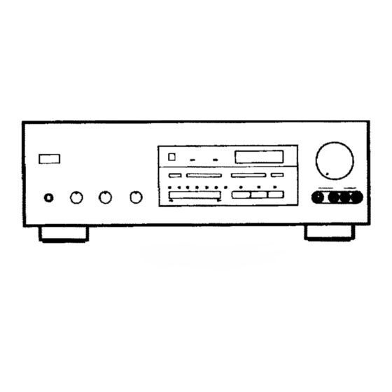
Page 20: 1-3.Controls & Adjustments
1-3. CONTROLS & ADJUSTMENTS FRONT PANEL 1 Power Switch * STANDBY Mode (Europe model only) While the power is on, pressing the POWER key on the remote control unit switches the unit to the STANDBY mode. (In this mode, the indicator is half illuminated.) 2 Remote control sensor Signals from the remote control unit are received here. - Page 21 5 Input Trim Control Adjusts the input level of each source respectively. 6 Program Selector Sequentially selects the digital sound field processing programs in the + or – direction. 6 Display Panel Shows program names, parameters and information about other various settings and adjustments.
- Page 22 2 YPC/USER/LEARN Switch Set to YPC for operating this unit and Yamaha equipments. Set to USER for using learned key functions. Set to LEARN for learning new control functions. (See page 37.) (“YPC”...
- Page 23 Select DSP programs 1 through 12. K Tuner Function Keys Operate Yamaha tuner functions. L Tape Deck Function Keys Operate Yamaha tape deck functions. M Blank Keys Have no preset functions, so are used for learning other remote controller’s functions only.
-
Page 24: 1-4.Adjustment
1-4. ADJUSTMENT MAIN/CENTER/EFFECT SPEAKER LEVEL BALANCE ADJUSTMENT This operation uses an internal test-tone generator for balancing the levels of the main, center and effect speakers. 1. Depress the TEST switch on the remote control so that “TEST DOLBY SUR.” appears in the display panel to enter test mode. A hiss-like calibration signal should be heard from the left main speaker, center speaker(s), right main speaker and rear effect speakers in turn (see diagram). - Page 25 INPUT LEVEL ADJUSTMENT This adjustment is important for obtaining the best performance from the internal circuits of this unit. The optimum input level of this unit is pre-adjusted on the basis of the CD source level. This adjustment should be performed on all input sources in your system respectively, so that their levels match the CD source level as closely as possible.
- Page 26 OTHER IMPORTANT SETTINGS AND ADJUSTMENTS IN THE “SET/MENU” MODE The following five types of settings and adjustments should be done before enjoying audio and video sources. Note that these settings and adjustments cannot be done without monitoring the display information (or the information displayed on the monitor screen).
- Page 27 DESCRIPTIONS OF THE ITEMS 1. Selecting Center Mode (CENTER MODE NRML/WD/ PHNTM) In Normal (NRML) position, any frequency below 100 Hz will be divided between the main left and main right speakers. For this reason even a speaker smaller than the main left and right speakers can obtain a sufficient effect.
- Page 28 3. Initializing parameters on a DSP program (PARAMETER INIT) You can initialize all edited parameters on a DSP program. Note that a DSP program (except CHURCH) has two sub-programs; all parameters on both sub-programs are initialized by this operation. Operating procedure After selecting this item (title) in step 2 on page 24, press the Parameter + or –...
-
Page 29: General Operation
GENERAL OPERATION 2-1. PLAYING A SOURCE 1. Set the MASTER VOLUME control to minimum. Front panel 2. Turn the power on. Front panel 3. Select an input source. (The selected source is shown by the display panel, the monitor screen and illumination of the corresponding indicator over the input selector switches.) Front panel On the front panel, VCR 1, CD or LD can be selected directly by... -
Page 30: 2-2.Recording A Source To Audio/Video Tape
2-2. RECORDING A SOURCE TO AUDIO/VIDEO TAPE (OR DUBBING FROM A TAPE TO ANOTHER) To record an input source to be played 1. Press the REC OUT switch (so that “REC OUT ... ” appears on the display and the monitor screen). Front panel 2. - Page 31 To record a source other than the input source to be played This unit has a function of selecting a source to be recorded to tape deck or VCRs independent of the selection of input source. 1. Press the REC OUT switch ( so that “REC OUT ... ” appears on the display and the monitor screen).
-
Page 32: 2-3.Digital Sound Field Programs
NOTE: Adjusting the MASTER VOLUME, BASS, TREBLE controls, etc., or selecting a sound field program has no effect on the material being recorded. NOTE: Composite video and S video signals pass independently through this unit’s video circuits. Therefore, when recording or dubbing video signals between two video cassette recorders, if your source VCR is connected to provide only S video (or only composite video) signals, you can record only a S video (or only a composite... -
Page 33: 2-5.Muting The Effect Sound
3. All sound field programs except CHURCH have two “sub- programs” (see “2-7. DESCRIPTIONS OF THE SOUND FIELD PROGRAMS”). The sub-programs are selected using the Parameter +/– keys on the remote control unit. The CONCERT HALL 1 program, for example, contains the sub-programs “Hall A in Europe” and “Hall B in Europe”. -
Page 34: 2-7.Descriptions Of The Sound Field Programs
2-7. DESCRIPTIONS OF THE SOUND FIELD PROGRAMS The following list gives brief descriptions of the sound fields produced by each of the DSP programs. Keep in mind that most of these are precise digital recreations of actual acoustic environments. The data for them was recorded at the locations described using sophisticated sound field measurement equipment. - Page 35 3. CONCERT HALL 3 Hall E in Europe: A classic large shoe-box type concert hall with approximately 2200 seats. It has a circular stage and seats located behind the stage. Live Concert: A large round concert hall with a rich surround effect.
- Page 36 7. TV THEATER 1 Game/Amusement: The sound field of a disco is used for the front presence side, and the sound field of a concert hall in Vienna is used for the rear surround side. This program reproduces video game music etc.
- Page 37 9. CONCERT VIDEO Classical/Opera: This program provides excellent depth of vocals and overall clarity, restraining excessive reverberation. For opera, the orchestra pit and the stage are ideally combined, letting you feel a full presence sound. The rear surround side of the sound field is relatively moderated, however, it reproduces beautiful sound by the use of the data of a concert hall.You...
- Page 38 11. MOVIE THEATER Ideal for reproducing video discs, video tapes and similar sources which are Dolby Surround encoded and bear the “DOLBY SURROUND” logo. 70 mm Adventure: This program is ideal for precisely reproducing the sound design of the newest movies. The sound field is made according to the design of the newest movie theaters, so the reverberations of the sound field itself are restrained as...
-
Page 39: 2-8.Remote Control "Learning" Function
The remote control unit, in addition to controlling the most commonly used functions of the main unit and other connected Yamaha audio and video equipment, has a sophisticated “learning” function that allows it to control other equipment in your system equipped with infrared remote control receivers. - Page 40 NOTE: The originally preset function of a key is still available in the USER position if the key does not learn a new function. NOTE: If all signals learned are long signals, it is possible that the capacity of the memory could be completely filled before all of the keys learn new functions, and so no further learning is possible.
-
Page 41: Creating Your Own Sound Fields
In each program, those parameters are preset with values precisely calculated by Yamaha to create the sound field unique for the program. It is recommended to use DSP programs without changing values of parameters, however, this unit also allows you to create your own sound fields. - Page 42 In addition to the “TYPE” parameter which selects the sub- programs within each sound field program (e.g. “Hall A in Europe” and “Hall B in Europe” for program 1, “CONCERT HALL 1”), each program also has a set of parameters that allow you to change the characteristics of the acoustic environment to create precisely the effect you want.
-
Page 43: 3-2.Descriptions Of The Digital Sound Field Parameters
3-2. DESCRIPTIONS OF THE DIGITAL SOUND FIELD PARAMETERS Not all of the following parameters are found in every program. ROOM SIZE How it Affects the Sound: Changes the apparent size of the music venue. The larger the value, the larger the simulated room will sound. What it Does: Adjusts the timing between the early reflections. - Page 44 LIVENESS How it Affects the Sound: This parameter changes the apparent reflectivity of the walls in the hall. The early reflections from a sound source will lose intensity (decay) much faster in a room with acoustically absorbent wall surfaces than in one which has mostly reflective surfaces. A room with highly reflective surfaces in which the early reflections decay slowly is termed “live”, while a room with absorbent characteristics in which the reflections decay rapidly is termed “dead”.
- Page 45 DIR. ENHANCEMENT (Directional Enhancement) This circuit emphasizes the position of sound. If this circuit is activated, the unity constituent of the input left and right channels (those signals which are common to the left and right channels) will be output from the center speaker, and the disparity constituent of the left and right signals (the difference between the left and right channels) will be output from the surround speakers.
-
Page 46: Troubleshooting
PROBLEM Power does not come on. Hum. No sound. No sound from the effect speakers. No sound from the front effect speakers. No sound from the center speaker. The sound suddenly goes off. DSP parameters or other settings on this unit cannot be changed. -
Page 47: Specifications
Minimum RMS Output Power Per Channel Main (20 Hz – 20 kHz 0.015% THD 8Ω/6Ω) [U.S.A. and Canada models] ... 65W/80W [Australia, Europe, U.K. and General models] ... 60W/75W Center (20 Hz – 20 kHz 0.015% THD 8Ω/6Ω) [U.S.A. and Canada models] ... 65W/80W [Australia, Europe, U.K. - Page 48 YAMAHA ELECTRONICS (UK) LTD. YAMAHA HOUSE, 200 RICKMANSWORTH ROAD WATFORD, HERTS WD1 7JS, ENGLAND YAMAHA SCANDINAVIA A.B. J A WETTERGRENS GATA 1, BOX 30053, 400 43 VÄSTRA FRÖLUNDA, SWEDEN YAMAHA MUSIC AUSTRALIA PTY, LTD. 17-33 MARKET ST., SOUTH MELBOURNE, 3205 VIC., AUSTRALIA...