Table of Contents
Advertisement
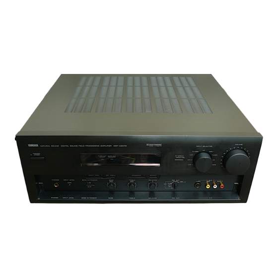
DSP-A2070
DIGITAL SOUND FIELD
PROCESSING AMPLIFIER
OPERATION MANUAL
CONTENTS
SAFETY INSTRUCTIONS..................................................Inside Front cover
SETUP & ADJUSTMENT ..............................................................................3
1-1.GETTING STARTED ...............................................................................3
1-2.SETUP....................................................................................................10
1-3.CONTROLS & ADJUSTMENTS ...........................................................19
1-4.ADJUSTMENT.......................................................................................23
GENERAL OPERATION .............................................................................29
2-1.PLAYING A SOURCE ...........................................................................29
2-2.RECORDING A SOURCE TO AUDIO/VIDEO TAPE ..........................30
2-3.DIGITAL SOUND FIELD PROGRAMS.................................................31
2-4.SELECTING SOUND FIELD PROGRAMS ..........................................31
2-5.MUTING THE EFFECT SOUND...........................................................32
DISPLAY ................................................................................................32
2-7.DESCRIPTIONS OF THE SOUND FIELD PROGRAMS.....................33
2-8.REMOTE CONTROL "LEARNING" FUNCTION..................................39
CREATING YOUR OWN SOUND FIELDS.................................................41
3-1.SELECTING AND EDITING PROGRAM PARAMETERS...................41
PARAMETERS ......................................................................................43
TABLES & SPECIFICATIONS....................................................................48
4-1.PROGRAM PARAMETER TABLE........................................................48
4-2.TROUBLESHOOTING ..........................................................................51
4-3.SPECIFICATIONS.................................................................................52
Advertisement
Table of Contents

Related Manuals for Yamaha DSP-A2070


Summary of Contents for Yamaha DSP-A2070
-
Page 1: Table Of Contents
DSP-A2070 DIGITAL SOUND FIELD PROCESSING AMPLIFIER OPERATION MANUAL CONTENTS SAFETY INSTRUCTIONS...Inside Front cover SETUP & ADJUSTMENT ...3 1-1.GETTING STARTED ...3 1-2.SETUP...10 1-3.CONTROLS & ADJUSTMENTS ...19 1-4.ADJUSTMENT...23 GENERAL OPERATION ...29 2-1.PLAYING A SOURCE ...29 2-2.RECORDING A SOURCE TO AUDIO/VIDEO TAPE ...30 (OR DUBBING FROM A TAPE TO ANOTHER) 2-3.DIGITAL SOUND FIELD PROGRAMS...31... -
Page 2: Safety Instructions
PRECAUTIONS & SAFETY INSTRUCTIONS SAFETY INSTRUCTIONS Read Instructions – All the safety and operating instructions should be CAUTION read before the unit is operated. RISK OF ELECTRIC SHOCK DO NOT OPEN Retain Instructions – The safety and operating instructions should be retained CAUTION: TO REDUCE THE RISK OF for future reference. - Page 3 This product, when installed as indicated in the instructions contained in this manual, meets FCC requirements. Modifications not expressly approved by Yamaha may void your authority, granted by the FCC, to use the product. 2. IMPORTANT : When connecting this product to accessories and/or another product use only high quality shielded cables.
- Page 4 You are the proud owner of a Yamaha Digital Sound Field Processing (DSP) System—an extremely sophisticated audio component. The DSP system takes full advantage of Yamaha’s undisputed leadership in the field of digital audio processing to bring you a whole new world of listening experiences.
-
Page 5: Setup & Adjustment
SETUP & ADJUSTMENT 1-1. GETTING STARTED Unpacking If you haven’t already done so, carefully remove this unit and its accessories from the box and wrapping material. You should find the unit itself and the following accessories. Remote control Batteries User program sheets Installing the Remote Control Unit Batteries Since the remote control unit will be used for many of this unit’s... - Page 6 Extensive research into the exact nature of the sonic reflections that create the ambience of a large hall has made it possible for Yamaha engineers to bring you this same sound in your own listening room, so you’ll feel all the sound of a live concert.
- Page 7 “MOVIE THEATER”, which recreates the listening experience of a 70 mm film theater. Directional Enhancement Circuit The YAMAHA directional enhancement (DIR. ENHANCEMENT) circuit expands and focuses the digital sound field. This effect puts you in the midst of the action, while centering and focusing your attention to the screen.
- Page 8 It is also possible to further expand your system with the addition of a subwoofer and amplifier. You may wish to choose the convenience of a Yamaha Active Servo Processing Sub Woofer System, which has its own built-in power amp.
-
Page 9: Speaker System
Four Possible Types of Speaker System Configurations Recommended 4 Speaker System 5 Speaker System Simplest system. Good for Audio/Video sources and Dolby Pro Logic Surround. You can enjoy widely diffused sound by With sound field programs No. 7 only adding two additional speaker units through No. - Page 10 SPEAKERS. (To avoid interference, keep the speaker above or below the television monitor, or use a magnetically shielded speaker.) If using a SUBWOOFER, such as a Yamaha Active Servo Sub- woofer System, the position of the speaker is not so critical because low bass tones are not highly directional.
- Page 11 VIDEO SUPERIMPOSE If you connect your video cassette recorder, video disc player, video monitor, etc. to this unit, you can take advantage of this unit’s capability to display program titles, parameter data and information about other various settings and adjustments on your video monitor’s screen.
-
Page 12: 1-2.Setup
1-2. SETUP Before you start making connections make sure all related electronic components are turned OFF. REAR PANEL CAUTION: TO PREVENT ELECTRIC SHOCK, DO NOT USE THIS (POLARIZED) PLUG WITH AN EXTENSION CORD, RECEPTACLE OR OTHER OUTLET UNLESS THE BLADES CAN BE FULLY INSERTED TO PREVENT BLADE EXPOSURE. - Page 13 1 GND Terminal Connects the ground wire of the turntable to produce minimum hum. In some cases, however, better results may be obtained with the ground wire disconnected. 2 Audio Signal Connection Jacks (for Audio Source Equipment) Connect the inputs and/or outputs of your audio equipment. 3 Audio/Video Signal Connection Jacks (for Video Source Equipment) Connect the audio and video inputs and/or outputs of your video...
- Page 14 E Center In Jack Line input to built-in center-channel amplifier. Connected with jumper bars to CENTER OUT jack when the built-in amplifier is used. Not connected when using an external power amplifier. F Mono Low Pass Jack When using a subwoofer, connect its amplifier input to this jack. Frequencies below 200 Hz from the left main, right main and center channels are output to this jack.
- Page 15 Rear Panel Switch and Control Settings There are several switches and controls on the rear panel that you’ll have to check before operating your system, and it’s a good idea to do it before you connect cables. Locate the MAIN LEVEL control (A) and FRONT MIX slide switch (:) at the bottom of the MAIN terminal group.
- Page 16 CONNECTING AUDIO/VIDEO SOURCE EQUIPMENTS TO THIS UNIT Turntable OUTPUT CD player OUTPUT Tuner OUTPUT Tape deck 1 LINE OUT LINE IN Tape deck 2 LINE OUT LINE IN If you wish to connect a second monitor TV (or a projector) to this unit, you can switch the VCR 3 VIDEO OUT jack (and S VIDEO jack also) to a second monitor out jack.
- Page 17 CONNECTING TO S VIDEO JACKS If your video cassette recorder, video disc player, etc. and your monitor are equipped with “S” (high-resolution) video terminals, connect them to this unit’s S VIDEO jacks, and connect this unit’s S VIDEO MONITOR OUT jack to the “S” video input of your monitor. Otherwise, connect the composite video jacks from your video cassette recorder, video disc player, etc.
- Page 18 CONNECTING THE MAIN SPEAKERS TO THIS UNIT Main speaker Main speaker Connect the MAIN speakers to the MAIN speaker output terminals of this unit. Make sure that the jumper bars between the MAIN OUT and MAIN IN jacks on the rear panel are in place. It is also possible to use an external power amplifier if more power is desired.
-
Page 19: Connecting Effect Speakers To This Unit
NOTE: The speaker connections above are fine for most applications. If for some reason, however, you wish to use an external power amp for any or all of the effect channels, connect the line level output jack(s) for each channel to the INPUT jacks of the external amp and connect the corresponding speaker pair to the speaker terminals of the external amp. - Page 20 LOW PASS jack to the INPUT jack of the amplifier driving the right subwoofer, and then connect each subwoofer to the corresponding amplifier. With some subwoofers, including the Yamaha Active Servo Processing Subwoofer System, the amplifier and subwoofer are in the same unit.
-
Page 21: 1-3.Controls & Adjustments
1-3. CONTROLS & ADJUSTMENTS FRONT PANEL 1 Power Switch * STANDBY Mode (Europe model only) While the power is on, pressing the POWER key on the remote control unit switches the unit to the STANDBY mode. (In this mode, the indicator is half illuminated.) 2 Remote control sensor Signals from the remote control unit are received here. - Page 22 7 Input Selector Selects the input source that you want to listen to (and watch). 8 Master Volume Control Simultaneously controls signal level at all outputs: front effect, main, rear effect, center, and subwoofer. (This does not affect TAPE REC OUT level.) 9 Phones Jack Plug in headphones here for private listening.
- Page 23 2 YPC/USER/LEARN Switch Set to YPC for operating this unit and Yamaha equipments. Set to USER for using learned key functions. Set to LEARN for learning new control functions. (See page 39.) (“YPC”...
- Page 24 Select programs 1 through 12. J Tuner Function Keys Operate Yamaha tuner functions. K Tape Deck Function Keys Operate Yamaha tape deck functions. L Blank Keys Have no preset functions, so are used for learning other remote controller’s functions only.
-
Page 25: 1-4.Adjustment
1-4. ADJUSTMENT MAIN/CENTER/EFFECT SPEAKER LEVEL BALANCE ADJUSTMENT This operation uses an internal test-tone generator for balancing the levels of the main, center and effect speakers. 1. Depress the TEST switch on the remote control so that “TEST DOLBY” appears in the display panel to enter test mode. A hiss-like calibration signal should be heard from the left main speaker, center speaker(s), right main speaker and rear effect speakers in turn (see diagram). - Page 26 INPUT LEVEL ADJUSTMENT This adjustment is important for obtaining the best performance from the internal circuits of this unit. The optimum input level of this unit is pre-adjusted on the basis of the CD source level. This adjustment should be performed on all input sources in your system respectively, so that their levels match the CD source level as closely as possible.
- Page 27 OTHER IMPORTANT SETTINGS AND ADJUSTMENTS The following seven types of settings and adjustments should be done before enjoying audio and video sources. Note that these settings and adjustments cannot be done without monitoring the display information (or the information displayed on the monitor screen).
- Page 28 DESCRIPTIONS OF THE ITEMS 1. Selecting Center Mode (CENTER MODE NRML/WD/ PHNTM) In Normal (NRML) position, any frequency below 100 Hz will be divided between the main left and main right speakers. For this reason even a speaker smaller than the main left and right speakers can obtain a sufficient effect.
- Page 29 3. Adjusting subwoofer level by the use of test-tone (LOW FREQ. TEST) The internal low frequency test-tone generator is useful for adjusting subwoofer level to make the subwoofer sound match the sound of other speakers in your audio system. Operating procedure 1.
- Page 30 4. Initializing parameters on a DSP program (PARAMETER INIT) You can initialize all edited parameters on a DSP program. Note that a DSP program has two sub-programs; all parameters on both sub-programs are initialized by this operation. Operating procedure This operation cannot be done without the remote control unit.
-
Page 31: General Operation
GENERAL OPERATION 2-1. PLAYING A SOURCE 1. Set the MASTER VOLUME control to minimum. Front panel 2. Turn the power on. Front panel POWER POWER 3. Select a source. Front panel INPUT SELECTOR PHONO TV/DBS TAPE 1 VCR 1 TUNER TAPE 2 VCR 3 VCR 2... -
Page 32: 2-2.Recording A Source To Audio/Video Tape
2-2. RECORDING A SOURCE TO AUDIO/VIDEO TAPE (OR DUBBING FROM A TAPE TO ANOTHER) 1. Set the REC OUT selector to the SOURCE position. 2. Select the source to be recorded. Front panel INPUT SELECTOR TV/DBS TAPE 1 VCR 1 TUNER TAPE 2 MONITOR... -
Page 33: 2-3.Digital Sound Field Programs
NOTE: Adjusting the MASTER VOLUME, BASS, TREBLE controls, etc., or selecting a sound field program has no effect on the material being recorded. NOTE: Please check the copyright laws in your country to record from records, compact discs, radio, etc. Recording of copyright material may infringe copyright laws. -
Page 34: 2-5.Muting The Effect Sound
3. All sound field programs have two “sub-programs” (see “2-7. DESCRIPTIONS OF THE SOUND FIELD PROGRAMS”). The sub- programs are selected using the Parameter +/– keys on the remote control unit. The CONCERT HALL 1 program, for example, contains the sub-programs “Hall A in Europe” and “Hall B in Europe”. When the CONCERT HALL 1 program is first selected, the “Hall A in Europe”... -
Page 35: 2-7.Descriptions Of The Sound Field Programs
2-7. DESCRIPTIONS OF THE SOUND FIELD PROGRAMS The following list gives brief descriptions of the sound fields produced by each of the DSP programs. Keep in mind that most of these are precise digital recreations of actual acoustic environments. The data for them was recorded at the locations described using sophisticated sound field measurement equipment. - Page 36 3. CONCERT HALL 3 Hall E in Europe: A classic large 2200-seat concert hall with a circle stage and seats behind the stage. Preset Parameter EFCT TRIM 0 dB INIT. DLY 30 ms ROOM SIZE 1.0 LIVENESS 5 Live Concert: A round concert hall with a rich “surround”...
- Page 37 5. ROCK CONCERT The Roxy Theatre: The ideal program for lively, dynamic rock music. The data for this program was recorded at LA’s “hottest” rock club. Preset Parameter EFCT TRIM 0 dB INIT. DLY 15 ms ROOM SIZE 1.0 LIVENESS 5 REV.
- Page 38 7. CONCERT VIDEO 1 Classical/Opera: This program provides excellent depth of vocals and overall clarity. For opera, the orchestra pit and the stage are ideally combined, letting you feel a full presence sound. Preset Parameter EFCT TRIM 0 dB DIR. ENHANCEMENT MID P.
- Page 39 9. TV THEATER Mono Movie: This program is ideal for reproducing monaural video sources (old movies etc.). Monaural sounds are reproduced with strong presence by creating moderate reverberation, while conversations are oriented to the screen. Preset Parameter EFCT TRIM 0 dB DIR.
- Page 40 11. MOVIE THEATER 2 Ideal for reproducing video discs, video tapes and similar sources which are Dolby Surround encoded and bear the “DOLBY SURROUND” logo. 70 mm Adventure: This program is ideal for precisely reproducing the sound design of the newest movies.
-
Page 41: 2-8.Remote Control "Learning" Function
The remote control unit, in addition to controlling the most commonly used functions of the main unit and other connected Yamaha audio and video equipment, has a sophisticated “learning” function that allows it to control other equipment in your system or other household appliances equipped with infrared remote control receivers. - Page 42 NOTE: The originally preset function of a key is still available in the USER position if the key does not learn a new function. NOTE: If all signals learned are long signals, it is possible that the capacity of the memory could be completely filled before all of the keys learn new functions, and so no further learning is possible.
-
Page 43: Creating Your Own Sound Fields
This ability to create sound fields at will is exactly what Yamaha has done with the DSP system. In addition to allowing you to recreate the sound fields of famous listening environments from around the world, the DSP system allows you to create your own sound fields. - Page 44 In addition to the “TYPE” parameter which selects the sub- programs within each sound field program (e.g. “Hall A in Europe” and “Hall B in Europe” for program 1, “CONCERT HALL 1”), each program also has a set of parameters that allow you to change the characteristics of the acoustic environment to create precisely the effect you want.
-
Page 45: 3-2.Descriptions Of The Digital Sound Field Parameters
3-2. DESCRIPTIONS OF THE DIGITAL SOUND FIELD PARAMETERS Not all of the following parameters are found in every program. Refer to the “PROGRAM PARAMETER TABLE” on page 48 for a complete list of the parameters in each program. ROOM SIZE How it Affects the Sound: Changes the apparent size of the music venue. - Page 46 LIVENESS How it Affects the Sound: This parameter changes the apparent reflectivity of the walls in the hall. The early reflections from a sound source will lose intensity (decay) much faster in a room with acoustically absorbent wall surfaces than in one which has mostly reflective surfaces. A room with highly reflective surfaces in which the early reflections decay slowly is termed “live”, while a room with absorbent characteristics in which the reflections decay rapidly is termed “dead”.
- Page 47 REV. DELAY (Reverberation Delay) This parameter sets the time difference between the beginning of the direct sound and the beginning of the reverberation sound. The larger the value, the later the reverberation sound will begin. A later reverberation sound makes you feel like the space of the acoustic environment has become larger.
- Page 48 DIR. ENHANCEMENT (Directional Enhancement) This circuit emphasizes the position of sound. If this circuit is activated, the unity constituent of the input left and right channels (those signals which are common to the left and right channels) will be output from the center speaker, and the disparity constituent of the left and right signals (the difference between the left and right channels) will be output from the surround speakers.
- Page 49 EFCT TRIM (Effect Trim) Performs fine adjustment of the level of all the effect sounds. Control Range: –3 dB to 3 dB P. INIT DLY (Presence Initial Delay) Adjusts the delay between the direct sound and the first reflection on the presence side of the sound field. The larger the value, the later the first reflection begins.
-
Page 50: Tables & Specifications
TABLES & SPECIFICATIONS 4-1. PROGRAM PARAMETER TABLE If you alter parameters, write down the altered values on the table. If parameters are initialized because of a mis-operation or a long (more than two weeks) cut in power, you can restore your custom values by adjusting parameters according to the table. - Page 51 Program Name Parameter Name JAZZ CLUB DIR. ENHANCEMENT CONCERT VIDEO 1 P. ROOM SIZE S. ROOM SIZE DIR. ENHANCEMENT P. ROOM SIZE CONCERT VIDEO 2 S. ROOM SIZE DIR. ENHANCEMENT P. ROOM SIZE TV THEATER S. ROOM SIZE Preset Value Village Gate TYPE EFCT TRIM...
- Page 52 Program Name MOVIE THEATER 1 MOVIE THEATER 2 DOLBY PRO LOGIC Parameter Name Preset Value TYPE 70 mm Spectacle EFCT TRIM 0 dB DOLBY PRO LOGIC P. INIT. DLY 13 ms P. ROOM SIZE S. DELAY 23 ms S. ROOM SIZE 70 mm Adventure TYPE 0 dB...
-
Page 53: 4-2.Troubleshooting
4-2. TROUBLESHOOTING PROBLEM POSSIBLE CAUSE Power does not come on. AC cord not properly plugged in. Hum. Bad cable connection. No sound. Bad or incorrect input connection. Incorrect input source selection. No sound from main speakers. The MAIN LEVEL control is set to “0”. No sound from effect speakers. -
Page 54: 4-3.Specifications
4-3. SPECIFICATIONS Minimum RMS Output Power Per Channel Main (20 Hz – 20 kHz 0.015% THD 8Ω/6Ω) ... 80W/100W Center (20 Hz – 20 kHz 0.015% THD 8Ω/6Ω) [U.S.A., Canada and General models] ... 80W/100W [Australia, Europe and U.K. models] ... 80W/100W Front, Rear Effect (20 Hz –... - Page 55 Tone Control Characteristics Bass Boost/Cut ... ±10 dB (50 Hz) Turnover frequency ... 350 Hz Treble Boost/Cut ... ±10 dB (20 kHz) Turnover frequency ... 3.5 kHz BASS EXTENSION ... +7 dB (70 Hz) Filter Characteristics (Highcut Filter) LOW PASS (fc = 200 Hz) ... 12 dB/oct. AUDIO MUTING ...
- Page 56 YAMAHA ELECTRONIK EUROPA G.m.b.H. SIEMENSSTR. 22-34, D-2084 RELLINGEN BEI HAMBURG, F.R. OF GERMANY YAMAHA ELECTRONIQUE FRANCE S.A. 17 RUE DES CAMPANULES, LOGNES 77321 MARNE LA VALLEE CEDEX 2, FRANCE YAMAHA ELECTRONICS (UK) LTD. YAMAHA HOUSE, 200 RICKMANSWORTH ROAD WATFORD, HERTS WD1 7JS, ENGLAND YAMAHA SCANDINAVIA A.B.