Yamaha DSP-A2 Owner's Manual
Natural sound av amplifier
Hide thumbs
Also See for DSP-A2:
- Owner's manual (90 pages) ,
- Service manual (85 pages) ,
- Owner's manual (534 pages)
Table of Contents
Advertisement
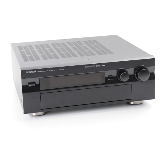
NATURAL SOUND
AV AMPLIFIER DSP-A2
STANDBY/ON
SPEAKERS
A
B
SET MENU
PHONES
BASS
TONE
EXTENSION
BYPASS
NATURAL SOUND AV AMPLIFIER
AMPLIFICATEUR AUDIO-VIDEO
CINEMA DSP 7 ch
NEXT
EXT. DECODER
EFFECT
PROGRAM
BASS
TREBLE
BALANCE
REC OUT
0
0
SOURCE
0
l
l
l
l
l
l
DVD/LD
TAPE/MD
2
2
2
2
2
2
TV/DBS
3
3
3
3
VCR 1
3
3
VCR 2
4
4
4
4
4
4
VIDEO AUX
5
5
5
5
L
5
5
R
BEDIENUNGSANLEITUNG
BEDIENUNGSANLEITUNG
MANUALE DI ISTRUZIONI
MANUALE DI ISTRUZIONI
MANUAL DE INSTRUCCIONES
MANUAL DE INSTRUCCIONES
GEBRUIKSAANWIJZING
GEBRUIKSAANWIJZING
INPUT SELECTOR
INPUT MODE
VIDEO AUX
CD
TUNER
PHONO
OWNER'S MANUAL
OWNER'S MANUAL
MODE D'EMPLOI
MODE D'EMPLOI
BRUKSANVISNING
BRUKSANVISNING
G B R T
VOLUME
l6
20
l2
28
8
40
4
60
2
0
–dB
Advertisement
Table of Contents

Related Manuals for Yamaha DSP-A2


Summary of Contents for Yamaha DSP-A2
- Page 1 NATURAL SOUND AV AMPLIFIER AMPLIFICATEUR AUDIO-VIDEO NATURAL SOUND AV AMPLIFIER DSP-A2 STANDBY/ON SPEAKERS SET MENU NEXT EXT. DECODER PHONES BASS TONE BASS TREBLE EXTENSION BYPASS CINEMA DSP 7 ch INPUT SELECTOR INPUT MODE EFFECT PROGRAM BALANCE REC OUT SOURCE VIDEO AUX...
- Page 2 Congratulations! You are the proud owner of a Yamaha Digital Sound Field Processing (DSP) System—an extremely sophisticated audio component. The DSP system takes full advantage of Yamaha’s undisputed leadership in the field of digital audio processing to bring you a whole new world of listening experiences. Follow the instructions in this manual carefully when setting up your system, and the DSP system will sonically transform your room into a wide range of listening environments—anything from a...
-
Page 3: Table Of Contents
CONTENTS CAUTION ... 2 INTRODUCTION ... 3 Features ... 3 What’s DSP?... 4 GETTING STARTED ... 7 Getting started... 7 Unpacking ... 7 Opening and closing the front cover ... 7 Installing batteries in the remote controller ... 8 Notes about the remote controller... 8 Controls and their functions ... -
Page 4: Caution
The voltage used must be the same as that specified on this unit. Using this unit with a higher voltage than specified is dangerous and may result in fire or other accidents. YAMAHA will not be held responsible for any damage resulting from use of this unit with a voltage other than specified. -
Page 5: Introduction
Dolby Pro Logic Surround Decoder DTS Decoder CINEMA DSP: Theater-like Sound Experience by the Combination of YAMAHA DSP Technology and Dolby Digital, Dolby Pro Logic or DTS Automatic Input Balance Control for Dolby Pro Logic Surround Test Tone Generator for Easier Speaker... -
Page 6: What's Dsp
However, something has still been missing: The atmosphere and acoustic ambiance of the public venue. Our Yamaha engineers have extensively researched the nature of sound acoustics and the way sound reflects inside a room. We sent these engineers to famous theaters and concert halls around the world to measure the acoustics of those venues with sophisticated microphones. -
Page 7: Dolby Digital
Dolby Digital Dolby Digital is the next level of Dolby Surround sound system developed for 35 mm film-movies by employing low bit-rate audio coding. Dolby Digital is a digital surround sound system that provides completely independent multi-channel audio to you. Dolby Digital provides five full range channels in what is sometimes referred to as a “3/2”... - Page 8 12 is selected, and the input signal of the source is analog, PCM audio or encoded with the Dolby Digital in 2-channels. However, Yamaha DSP technology allows you to create nearly the same sound experience as that of a large movie theater in...
-
Page 9: Getting Started
Getting started Unpacking Carefully remove this unit and accessories from the box. You should find the unit itself and the following accessories. Remote controller Opening and closing the front cover Close the front cover whenever the controls inside the panel are not used. To open the front cover GETTING STARTED User function stickers... -
Page 10: Installing Batteries In The Remote Controller
GETTING STARTED Installing batteries in the remote controller Since the remote controller will be used for many of this unit’s control operations, you should begin by installing the supplied batteries. Turn the remote controller over and slide the battery compartment cover in the direction of the arrow. Insert the batteries (AA, LR6, UM-3 type) according to the polarity markings on the inside of the battery compartment. -
Page 11: Controls And Their Functions
Controls and their functions Front panel NATURAL SOUND AV AMPLIFIER DSP A2 STANDBY/ON SPEAKERS SET MENU PHONES BASS TONE EXTENSION BYPASS For the remote controller, refer to pages 60 to 61. STANDBY/ON switch Press this switch to turn on the power. Press this switch again to set this unit in the standby mode. - Page 12 GETTING STARTED SPEAKERS switches Press the switch A or B (or both) for the main speakers you will use to select them. Press the switch for the main speakers you will not use again to cancel them. On the display panel, “SPEAKERS A”...
-
Page 13: Display Panel
Display panel DIGITAL PRO LOGIC SPEAKERS indicators Either of the “dts” indicators will be illuminated when the built-in DTS decoder is turned on. A red “dts” indicator will be illuminated when playing a compact disc or laserdisc encoded with DTS. An orange “dts”... -
Page 14: Preparation
If using a SUBWOOFER, such as a Yamaha Active Servo Processing Subwoofer System, the position of the speaker is not so critical because low bass tones are not highly directional. -
Page 15: Speaker System
The rear speakers and the front effect speakers produces a 360-degree sound field, and the center speaker provides precise center localization. You can experience the amazing YAMAHA “CINEMA DSP” sound fields completely with the 7 speaker system. 1E. SYS. SETUP—Set to 7ch. (See page 27.) 1A. -
Page 16: Connections
Use RCA type pin plug cables for audio/video units with the exception described later. The output (or input) terminals of YAMAHA audio/video units numbered as 1, 2, 3, 4, etc. on the rear panel must be connected to the same-numbered terminals of this unit. - Page 17 Basic connections of video units (Europe model) AUDIO SIGNAL AUDIO SIGNAL PHONO DIGITAL RF SIGNAL DVD/LD COAXIAL ( PLAY ) OPTICAL TAPE/MD ( REC ) MAIN (PLAY) SURROUND TAPE/MD (REC) DVD/LD SUB WOOFER CENTER EXTERNAL DECODER INPUT TV/DBS DIGITAL SIGNAL VIDEO AUX terminals (on the front panel) These terminals are used to connect a video input source such as a camcorder.
- Page 18 PREPARATION For connecting with a TV monitor that uses a 21 pin connector for input (Europe and U.K. models only) Make a connection as figured below with a commercially available scart-plug connector cable. MAIN (PLAY) SURROUND TAPE/MD (REC) DVD/LD SUB WOOFER CENTER EXTERNAL DECODER INPUT TV/DBS...
- Page 19 Connecting to digital (OPTICAL and COAXIAL) terminals If your CD player, MD recorder, LD player, DVD player, TV/satellite tuner, etc. are equipped with coaxial or optical digital audio signal output terminals, they can be connected to this unit’s COAXIAL or OPTICAL, or both terminals. Digital audio signals are transmitted with less loss than analog audio signals.
- Page 20 PREPARATION Connecting to DOLBY DIGITAL RF output of the DVD/LD/CD combi-player If your DVD/LD/CD combi-player has a DOLBY DIGITAL RF signal output terminal, connect it to this unit’s SIGNAL input terminal. Audio signals of an LD source encoded with the Dolby Digital are input to this unit by this connection. * To play back an LD source with the Dolby Digital decoded, set the input mode of DVD/LD to “AUTO”...
- Page 21 Connecting to S VIDEO terminals If your video cassette recorder, LD player, etc. and your monitor are equipped with “S” video terminals, connect them to this unit’s S VIDEO terminals, and connect this unit’s S VIDEO MONITOR OUT terminal to the “S” video input of your monitor. With this connection, you can play back and record high quality pictures.
- Page 22 PREPARATION Connecting an external decoder of a future format to this unit This unit is equipped with additional 6-channel audio signal input terminals (for left main, right main, center, left rear surround, right rear surround and subwoofer channels) for inputting signals from an external decoder of a future format to this unit.
-
Page 23: Speakers
Speakers Use speakers with the specified impedance shown on the rear of this unit. Front effect speakers Right COUPLER MAIN Center speaker MAIN Subwoofer system How to Connect: Connect the SPEAKERS terminals to your speakers with the wire of the proper gauge (keep as short as possible). If the connections are faulty, no sound will be heard from the speakers. -
Page 24: Impedance Selector Switch
INPUT terminal of the subwoofer amplifier, and connect the speaker terminals of the subwoofer amplifier to the subwoofer. With some subwoofers, including the Yamaha Active Servo Processing Subwoofer System, the amplifier and subwoofer are in the same unit. Such a subwoofer needs only the connection between the SUBWOOFER terminal of this unit and the INPUT terminal of the subwoofer. - Page 25 To drive main, center, front effect and/or rear speakers with external amplifiers The speaker connections described on page 21 are fine for most applications. If for some reason, however, you wish to drive main, center, front effect and/or rear speakers with your existing amplifier, etc., the following terminals are available for connecting external amplifier(s) to this unit.
-
Page 26: Plugging In This Unit
PREPARATION Plugging in this unit • After completing all connections, plug the AC power cord into an AC outlet. SPEAKERS (*2) TION MANUAL FOR CORRECT SETTING. MAIN (General model) (*1): AC OUTLET(S) (Europe, China and General models) ... 3 SWITCHED OUTLETS (U.K. -
Page 27: On Screen Display
On screen display If you connect your VCR, LD player, video monitor, etc. to this unit, you can take advantage of this unit’s capability to display program titles, parameter data and information for various setting changes and adjustments on your video monitor screen. -
Page 28: Selecting The Output Modes ("Set Menu" Mode)
PREPARATION Selecting the output modes (“SET MENU” mode) The following functions control the output signals to the speakers in your audio system. When speaker connections are all completed, select a proper position on each function to maximize the performance of your speaker system. * For details about the SET MENU mode, refer to pages 50 to 53. - Page 29 1C. MAIN SP Choices: LARGE/SMALL Preset position: LARGE LARGE: If your main speakers have a high ability for bass reproduction. In this position, full range signals present at the main channels are output from the main speakers. SMALL: If your main speakers do not have a high ability for bass reproduction.
- Page 30 PREPARATION Changing selections Refer to the display panel or the monitor screen when changing the selections. NATURAL SOUND AV AMPLIFIER DSP A2 STANDBY/ON SPEAKERS SET MENU NEXT EXT. DECODER PHONES BASS TONE BASS TREBLE EXTENSION BYPASS When using the remote controller, set the PARAMETER /SET MENU switch to the SET MENU position.
-
Page 31: Speaker Balance Adjustment
Speaker balance adjustment This procedure lets you adjust the sound output level balance between the main, center, rear and front effect speakers using the built-in test tone generator. After the adjustments, the sound output level heard at the listening position will be the same from each speaker. - Page 32 PREPARATION NATURAL SOUND AV AMPLIFIER DSP A2 STANDBY/ON SPEAKERS SET MENU NEXT EXT. DECODER PHONES BASS TONE BASS EXTENSION BYPASS Turn up the volume. Remote control MUTE You will hear a test tone (like pink noise) from the left main speaker, then the center speaker, then the right main speaker, then the right rear speaker, and then the left rear speaker, for about 2.5 seconds each.
- Page 33 11, 13 For the front effect speaker level adjustment, press the TEST key on the remote controller again so that “TEST DSP” appears on the display. Remote control TEST A calibration signal should be heard from the main speakers and the front effect speakers in turn. Main Front effect Adjust the front effect speaker level by pressing the...
-
Page 34: Basic Operation
Playing a source NATURAL SOUND AV AMPLIFIER DSP A2 STANDBY/ON SPEAKERS SET MENU NEXT EXT. DECODER PHONES BASS TONE BASS TREBLE EXTENSION BYPASS Front panel VOLUME –dB ∞ Set to the “ ” position. Turn on the power. Front panel STANDBY/ON Select main speakers A or B. - Page 35 CINEMA DSP NATURAL SOUND AV AMPLIFIER DSP A2 STANDBY/ON SPEAKERS SET MENU NEXT EXT. DECODER EFFECT PROGRAM PHONES BASS TONE BASS TREBLE BALANCE REC OUT EXTENSION BYPASS SOURCE DVD/LD TAPE/MD TV/DBS VCR 1 VCR 2 VIDEO AUX The current input mode is also shown for a source that inputs two or more types of signals to this unit.
- Page 36 BASIC OPERATION When you finish using this unit Press the STANDBY/ON switch on the front panel or the STANDBY key on the remote controller to enter the standby mode. Front panel STANDBY/ON To select the source connected to this unit’s EXTERNAL DECODER INPUT terminals as the input source.
- Page 37 Switching the input mode This unit allows you to switch the input mode for sources that send two or more types of signals to this unit. For CD, TAPE/MD and TV/DBS sources: The following three input modes are provided. AUTO: This mode is automatically selected when you turn on the power of this unit.
- Page 38 BASIC OPERATION Notes on input mode selection The input mode for a TV/DBS source is selected with function “7. TV/DBS INPUT” in the SET MENU mode. This unit will be automatically set to the selected input mode when the power is turned on. Set the input mode to the AUTO or D.D.RF mode to play a DVD/LD source encoded with Dolby Digital.
-
Page 39: Recording A Source To Tape (Or Md) Or Dubbing From Tape (Or Md) To Tape (Or Md)
Recording a source to tape (or MD) or dubbing from tape (or MD) to tape (or MD) Recording the playing source to tape (or MD) CINEMA DSP NATURAL SOUND AV AMPLIFIER DSP A2 STANDBY/ON SPEAKERS SET MENU NEXT EXT. DECODER EFFECT PHONES BASS... - Page 40 BASIC OPERATION Recording a source to tape (or MD) while listening to (or watching) another source The source (except for “SOURCE”) that is selected with the REC OUT selector can be recorded to a tape deck (MD recorder) and/or VCR, regardless of the INPUT SELECTOR setting. NATURAL SOUND AV AMPLIFIER DSP A2...
-
Page 41: Sound Control
Notes on recording The VOLUME, BASS, TREBLE, BALANCE controls, the BASS EXTENSION button and the settings of DSP have no effect on the material being recorded. Composite video and S video signals pass independently through this unit’s video circuits. Therefore, when recording or dubbing video signals, if your video source unit is connected to provide only a S video (or only a composite video) signal, you can record only a S video (or only a composite video) -
Page 42: Using Digital Sound Field Processor (Dsp)
DTS. The operation of these decoders can be controlled by selecting a corresponding DSP program including a combined operation of YAMAHA DSP and Dolby Digital, Dolby Pro Logic Surround or DTS. This unit has 12 programs for digital sound field processing; 7 from actual acoustic environments from around the world, and 5 programs for Audio/Video sources. - Page 43 CINEMA DSP NATURAL SOUND AV AMPLIFIER DSP A2 STANDBY/ON SPEAKERS SET MENU NEXT EXT. DECODER EFFECT PHONES BASS TONE BASS TREBLE BALANCE EXTENSION BYPASS Select a program that is suitable for the source. When operating on the front panel: PROGRAM Press once or more.
- Page 44 BASIC OPERATION To enjoy a video source encoded with Dolby Pro Logic Surround, Dolby Digital or DTS When you select the program No. 10, 11 or 12, and the input signal of the source is 2-channel stereo, Dolby Pro Logic Surround is decoded.
-
Page 45: Adjusting Output Level Of The Center, Right Rear, Left Rear, Front Effect Speakers And Subwoofer
Adjusting output level of the center, right rear, left rear, front effect speakers and subwoofer You can adjust the sound output level of the each speaker even if the output level is already set in “Speaker balance adjustment” on pages 29 to 31. C E N T E R R S U R . - Page 46 BASIC OPERATION Speakers CENTER RIGHT SURROUND (R SUR.) LEFT SURROUND (L SUR.) FRONT SUBWOOFER (SWFR) Notes Once the output level is adjusted, the level value will be the same in all the digital sound field programs. The value of each speaker output level you set the last time will remain memorized even when this unit is in the standby mode.
-
Page 47: Brief Overview Of Digital Sound Field Programs
Brief overview of digital sound field programs The following list gives you a brief description of the sound fields produced by each of the DSP programs. Keep in mind that most of these are precise digital recreations of actual acoustic environments. The data for these sound fields were recorded at actual locations using sophisticated sound field measurement equipment. - Page 48 BASIC OPERATION PROGRAM SUBPROGRAM (TYPE) JAZZ CLUB The Bottom Line Village Gate ROCK Roxy Theatre CONCERT Arena ENTERTAINMENT Disco Party STADIUM Anaheim Bowl FEATURE This is the sound field at stage front in “The Bottom Line”, a famous New York Jazz club. The floor can seat 300 people to the left and right in a sound field offering real and vibrant sound.
- Page 49 Program No. 8 to 12: CINEMA-DSP programs (for Audio/Video sources) These programs use the Dolby Pro Logic decoder, the Dolby Digital decoder or the DTS decoder. Speaker output for each program is as follows. No. 8, 9, 10, 11: main, center, rear, front effect No.
- Page 50 BASIC OPERATION Program No. 10 to 11 are suitable for reproducing video discs, video tapes and similar sources which are encoded with Dolby Surround (bearing the “DOLBY SURROUND” or “DOLBY DIGITAL” logo) or encoded with DTS (bearing the “dts” logo). PROGRAM MOVIE 70 mm Spectacle...
- Page 51 Program No. 12 is for reproducing video discs, video tapes and similar sources which are encoded with Dolby Surround (bearing the “DOLBY SURROUND” or “DOLBY DIGITAL” logo) or encoded with DTS (bearing the “dts” logo). PROGRAM SUBPROGRAM (TYPE) /DTS PRO LOGIC/Normal ( SURROUND Functions when the input signal is analog or PCM audio or encoded with Dolby...
-
Page 52: Advanced Features
“SET MENU” mode The following eight functions maximize the performance of your system and increase the enjoyment of audio listening and video watching. 1. SPEAKER SET 1A. CENTER SP 1B. REAR SP 1C. MAIN SP 1D. LFE/BASS OUT 1E. SYS. SETUP 1F. - Page 53 Function description 1. SPEAKER SET (Selecting the output modes suitable for your speaker system) Refer to pages 26 to 27 for details. (Once you have selected proper modes, you do not have to make a setting change, unless your speaker system is modified.) 2.
- Page 54 ADVANCED FEATURES 3. DTS SET Adjusting method After selecting the title “3. DTS SET” in step 1 on page 50, press the + or – key to display the title “3A. LFE LEVEL”. Then adjust its level with the + or – key. 3A.
- Page 55 6. MEMORY GUARD (Locking DSP parameters and other adjustments) If you wish to prevent accidental alteration to DSP parameters and other adjustments on this unit, select “ON”. In this position, they are locked and cannot be changed. The following functions on this unit can be locked by this operation. 7.
-
Page 56: Creating Your Own Sound Fields
This ability to create sound fields at will is exactly what Yamaha has done with the DSP. -
Page 57: Selecting And Editing Program Parameters
Selecting and editing program parameters This adjustment can be made only by using the remote controller and watching the monitor screen or the display panel. Note Information on the monitor screen would be easier to see than the display panel. Set the PARAMETER/SET MENU switch to the PARAMETER position. -
Page 58: Descriptions Of The Digital Sound Field Parameters
ADVANCED FEATURES Descriptions of the digital sound field parameters Not all of the following parameters are found in every program. ROOM SIZE How it Affects the Sound: Changes the apparent size of the music venue. The larger the value, the larger the simulated room will sound. What it Does: Adjusts the timing between the early reflections. - Page 59 LIVENESS How it Affects the Sound: This parameter changes the apparent reflectivity of the walls in the hall. The early reflections from a sound source will lose intensity (decay) much faster in a room with acoustically absorbent wall surfaces than in one which has mostly reflective surfaces.
- Page 60 ADVANCED FEATURES REV. LEVEL (Reverberation Level) This parameter adjusts the volume of the reverberation sound. The larger the value, the stronger the reverberation becomes. Control Range: 0 – 100% Level Direct sound S. DELAY (Surround Delay) Adjusts the delay between the direct sound and the first reflection on the rear surround side sound field.
-
Page 61: Setting The Sleep Timer
Setting the SLEEP timer Use the built-in SLEEP timer to automatically turn this unit into the standby mode after the time you set elapses. The SLEEP timer is useful when you plan to fall asleep while this unit is playing back or recording a source. The SLEEP timer also automatically turns off external units connected to the SWITCHED AC OUTLET(S) on the rear of this unit. -
Page 62: Remote Controller
The remote controller can operate the main unit as well as other Yamaha audio and video components. The Macro feature allows you to program a series of functions in sequence onto a single key, or you can use one of the preset macros to operate other Yamaha components in your home theater. - Page 63 A/B/C switch. A/B/C switch Normally this switch is set to the “A” position. Use the “B” position to control a Yamaha DVD player with the CD/DVD/LD player keys ( ). Use the “C” position to control a Yamaha LD...
-
Page 64: Using The "Learning-Capable" Keys (Cover Is Open)
If the memory capacity of the remote controller becomes full, no further learning is possible even if some learning-capable keys are not occupied with new functions. If, for example, you store Yamaha codes only into this remote controller, up to about 50 functions can be stored. - Page 65 Notes • Area A cannot learn a new function. To store a new function, store it onto area B or C. • If a key which has a preset function learns a new function, the preset function will not work but is not deleted. When the learned function is cleared, the preset function is restored.
-
Page 66: Using Operation Control Keys (Cover Is Closed)
REMOTE CONTROLLER Using OPERATION CONTROL keys (Cover is closed) When the cover of the remote controller is closed, you can easily operate Yamaha components including learned functions by using the OPERATION CONTROL keys. REMOTE CONTROL TRANSMITTER ( * 1) POWER ON STANDBY Cover is closed. - Page 67 Examples of operations controlled by using the OPERATION CONTROL keys To operate a Yamaha CD player 1. Press the “CD” input selector key. 2. Use the OPERATION CONTROL keys. (They carry out the functions in area A of keys Play...
-
Page 68: Macro Operations (Cover Is Closed)
REMOTE CONTROLLER Macro operations (Cover is closed) The Macro feature makes it possible to operate a series of functions by pressing just one key. For example, when you want to play a CD, normally you would turn on the equipment, select the CD input, and press the play key to start playback. - Page 69 The Macro feature allows you to operate several remote control functions in a programmed order by pressing one macro key. (Also, refer to the table on page 62.) Function of the key (and area) carried out when a macro key is pressed Macro key (Turns on this unit.) TAPE/MD...
-
Page 70: Learning New Function
REMOTE CONTROLLER Methods of learning and clearing functions Learning a new function Place this remote controller and the other remote controller so that they face each other. This remote controller CLEAR LEARN MACRO (Press by using a ball-point pen or similar object.) * If there is no operation for about 30 seconds after the LEARN button is pressed, the TRANSMIT/LEARN indicator flashes rapidly and the current mode is canceled. -
Page 71: Making A New Macro
Making a new macro A new macro can be programmed onto any preset macro key in place of the factory preset functions. (See page 66 to know what keys are preset macro keys.) You can make as many as 13 new macro keys. A macro key can learn as many as seven functions of other keys. -
Page 72: Clearing Learned Functions
REMOTE CONTROLLER Clearing learned functions To Clear a Learned Function To clear a learned key function, press the LEARN button using a ball-point pen or similar object. To clear a macro you made, press the MACRO button. CLEAR LEARN MACRO Press and hold the CLEAR button using a ball-point pen or similar object. -
Page 73: Troubleshooting
Refer to the chart below when this unit does not function properly. If the problem you are experiencing is not listed below or if the instruction below does not help, disconnect the power cord and contact your authorized YAMAHA dealer or service center. - Page 74 TROUBLESHOOTING Problem DSP parameters and some other settings on this unit cannot be changed. “INPUT DATA ERR” appears on the display and no sound is heard. The sound field cannot be recorded. This unit does not operate properly. A source cannot be recorded by a tape deck or VCR connected to this unit.
- Page 75 When playing back a source encoded with DTS: Problem A loud hissing noise is heard when you play back a source encoded with DTS. A percussive noise is heard when you begin playing back a source encoded with DTS. No sound is heard when you play back a source encoded with DTS, even though the “AUTO”...
-
Page 76: Specifications
AUDIO SECTION Minimum RMS Output Power Per Channel (When both channels are driven) MAIN L/R (20 Hz to 20 kHz, 0.02% THD, 8 ohms) ... 100W+100W CENTER (20 Hz to 20 kHz, 0.02% THD, 8 ohms) ... 100W REAR L/R (20 Hz to 20 kHz, 0.02% THD, 8 ohms) ...100W+100W FRONT L/R (1 kHz, 0.05% THD, 8 ohms) ...25W+25W... - Page 77 VIDEO SECTION Video Signal Type [Europe and U.K. models] ... PAL [China and General models] ... NTSC/PAL Video Signal Level ... 1 Vp-p/75 ohms S-Video Signal Level Y ... 1 Vp-p/75 ohms C ... 0.286 Vp-p/75 ohms Maximum Input Level ...1.5 Vp-p or more Signal-to-Noise Ratio ...50 dB or more Monitor Out Frequency Response ...
- Page 78 YAMAHA ELECTRONICS (UK) LTD. YAMAHA HOUSE, 200 RICKMANSWORTH ROAD WATFORD, HERTS WD1 7JS, ENGLAND YAMAHA SCANDINAVIA A.B. J A WETTERGRENS GATA 1, BOX 30053, 400 43 VÄSTRA FRÖLUNDA, SWEDEN YAMAHA MUSIC AUSTRALIA PTY, LTD. 17-33 MARKET ST., SOUTH MELBOURNE, 3205 VIC., AUSTRALIA...