Table of Contents
Advertisement
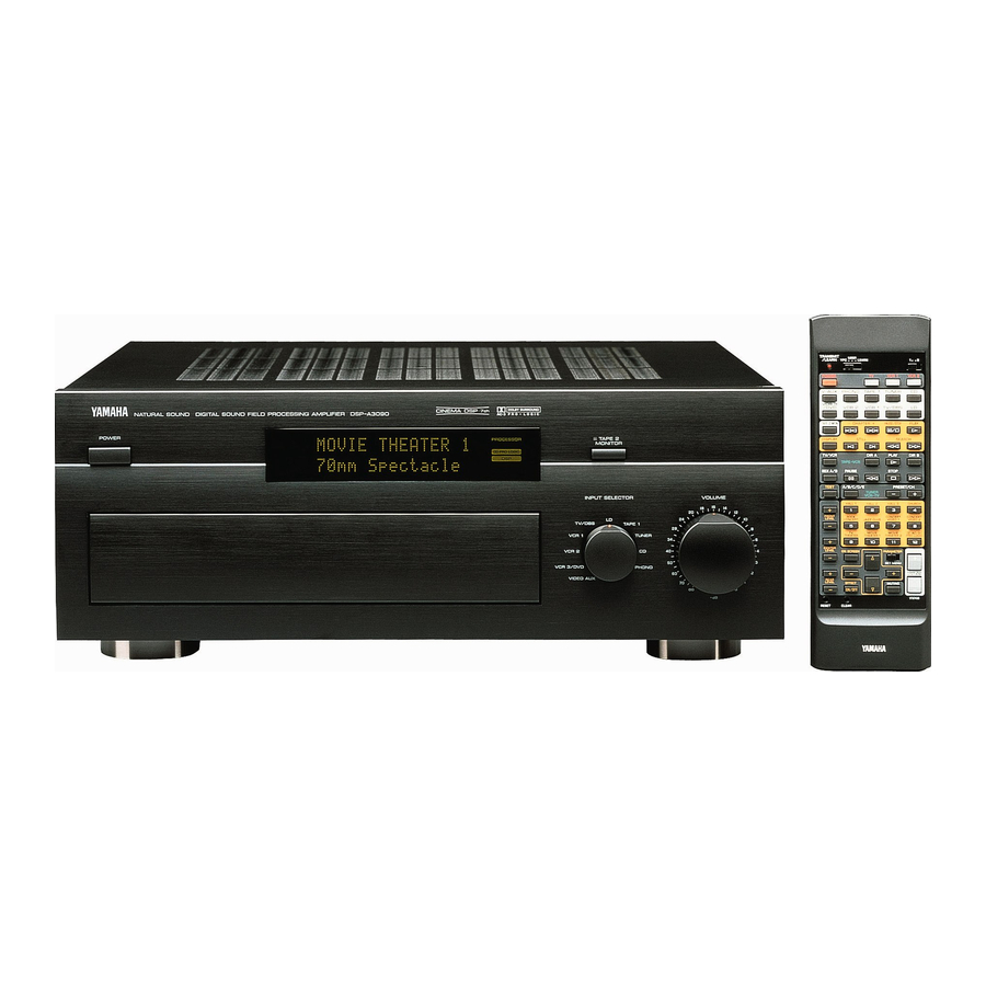
NATURAL SOUND DIGITAL SOUND FIELD PROCESSING AMPLIFIER
DSP A3090
POWER
INPUT TRIM
SET MENU
PROGRAM
PHONES
VIDEO AUX
BASS
BASS
TREBLE
EXTENSION
S VIDEO
VIDEO
L
AUDIO
R
CINEMA DSP
7ch
AC-3
PROCESSOR
TAPE 2
AC 3
MONITOR
PRO LOGIC
DSP
DIGITAL SOURCE
AC
3
PCM
INPUT SELECTOR
VOLUME
EFFECT
INPUT MODE
LD
TV/DBS
TAPE 1
VCR 1
TUNER
BALANCE
REC OUT
VCR 2
CD
SOURCE
TAPE 1
LD
CD
VCR 1
TV/DBS
VCR 2
VCR 3/DVD
PHONO
VCR 3/DVD
VIDEO AUX
VIDEO AUX
Advertisement
Table of Contents

Related Manuals for Yamaha DSP-A3090


Summary of Contents for Yamaha DSP-A3090
- Page 1 CINEMA DSP NATURAL SOUND DIGITAL SOUND FIELD PROCESSING AMPLIFIER DSP A3090 AC-3 PROCESSOR POWER AC 3 PRO LOGIC DIGITAL SOURCE INPUT TRIM SET MENU PROGRAM EFFECT INPUT MODE PHONES VIDEO AUX BASS BASS TREBLE BALANCE REC OUT EXTENSION S VIDEO VIDEO AUDIO SOURCE...
-
Page 2: Safety Instructions
PRECAUTIONS & SAFETY INSTRUCTIONS CAUTION RISK OF ELECTRIC SHOCK DO NOT OPEN CAUTION: TO REDUCE THE RISK OF ELECTRIC SHOCK, DO NOT REMOVE COVER (OR BACK). NO USER-SERVICEABLE PARTS INSIDE. REFER SERVICING TO QUALIFIED SERVICE PERSONNEL. • Explanation of Graphical Symbols The lightning flash with arrowhead symbol, within an equilateral triangle, is intended to alert you to the... - Page 3 If you can not locate the appropriate retailer, please contact Yamaha Electronics Corp., U.S.A. 6660 Orangethorpe Ave, Buena Park, CA 90620. The above statements apply ONLY to those products distributed by Yamaha Corporation of America or its subsidiaries.
- Page 4 5. DO NOT OPEN THE UNIT OR ATTEMPT REPAIRS OR MODIFICATIONS YOURSELF This product contains no user-serviceable parts. Refer all maintenance to qualified Yamaha service personnel. Opening the unit and/or tampering with the internal circuitry will make servicing difficult and will endanger you and your unit.
- Page 5 Congratulations! You are the proud owner of a Yamaha Digital Sound Field Processing (DSP) System—an extremely sophisticated audio component. The DSP system takes full advantage of Yamaha’s undisputed leadership in the field of digital audio processing to bring you a whole new world of listening experiences.
-
Page 6: Table Of Contents
PRECAUTIONS & SAFETY INSTRUCTIONS ...Inside the front cover GETTING STARTED...3 FEATURES...5 SPEAKER SETUP ...10 CONTROLS & THEIR FUNCTIONS ...13 FRONT PANEL ...13 REMOTE CONTROL UNIT ...16 CONNECTIONS ...18 REAR PANEL PARTS AND THEIR FUNCTIONS...18 REAR PANEL SWITCH AND CONTROL SETTINGS ...21 GENERAL INSTRUCTIONS FOR CONNECTIONS...21 CONNECTING AUDIO/VIDEO SOURCE EQUIPMENT TO THIS UNIT...22... -
Page 7: Getting Started
GETTING STARTED Unpacking If you haven’t already done so, carefully remove this unit and its accessories from the box and wrapping material. You should find the unit itself and the following accessories. Batteries Remote control User program sheets Installing the Remote Control Unit Batteries Since the remote control unit will be used for many of this unit’s control operations, you should begin by installing the supplied batteries. - Page 8 Notes about the Remote Control Unit When you notice that remote control operation has become erratic, or the distance from which the remote control will function has decreased, it’s time to replace the batteries. Always replace all batteries at the same time. * If you have exchanged batteries in the remote control unit with new ones, press the RESET button before using the remote control unit.
-
Page 9: Features
Extensive research into the exact nature of the sonic reflections that create the ambience of a large hall has made it possible for Yamaha engineers to bring you this same sound in your own listening room, so you’ll feel all the sound of a live concert. - Page 10 Dolby Pro Logic Surround This unit employs a Dolby Pro Logic Surround decoder similar to professional Dolby Stereo decoders used in many movie theaters. By using the Dolby Pro Logic Surround decoder, you can experience the dramatic realism and impact of Dolby Surround movie theater sound in your own home.
- Page 11 Yamaha DSP technology made it possible to present you with nearly the same sound experience as that of a large movie theater in...
- Page 12 Dolby Pro Logic + 2 Digital Sound Fields A digital sound field is created on the presence side and the rear surround side of the Dolby Pro Logic Surround-processed sound field individually. They create a wide acoustic environment and emphasize surround-effect in the room, letting you feel much presence as if you are watching a movie in a popular Dolby Stereo theater.
- Page 13 Video superimpose If you connect your video cassette recorder, LD player, video monitor, etc. to this unit, you can take advantage of this unit’s capability to display program titles, parameter data and information for various setting changes and adjustments on your video monitor’s screen.
-
Page 14: Speaker Setup
LFE (low frequency effect) sound with high fidelity when playing back a source with the Dolby Surround AC-3 decoded. You may wish to choose the convenience of a Yamaha Active Servo Processing Subwoofer System, which has its own built-... - Page 15 Four Possible Types of Speaker System Configurations Recommended 4 Speaker System 5 Speaker System Simplest system. Good for Audio/Video sources. You can enjoy widely diffused sound by By the use of center speaker, center only adding two additional speaker units sounds (dialog, vocals etc.) are at the rear.
- Page 16 SPEAKERS. (To avoid interference, keep the speaker above or below the television monitor, or use a magnetically shielded speaker.) If using a SUBWOOFER, such as a Yamaha Active Servo Subwoofer System, the position of the speaker is not so critical because low bass tones are not highly directional.
-
Page 17: Controls & Their Functions
CONTROLS & THEIR FUNCTIONS FRONT PANEL NATURAL SOUND DIGITAL SOUND FIELD PROCESSING AMPLIFIER POWER PHONES VIDEO AUX CINEMA DSP DSP A3090 AC-3 PROCESSOR PRO LOGIC DIGITAL SOURCE INPUT TRIM SET MENU PROGRAM EFFECT INPUT MODE BASS BASS TREBLE BALANCE REC OUT EXTENSION SOURCE TV/DBS... - Page 18 POWER Switch Turns this unit on and off. Standby Indicator (Europe, U.K. and Australia models only) While the power of this unit is on, pressing the POWER key on the remote control unit switches this unit to the standby mode. In this mode, the standby indicator is half illuminated.
- Page 19 BASS and TREBLE Controls Adjust low and high frequency response respectively for the left main, right main and center channels only. * Increasing low frequency response with the BASS control will not be so effective if you set the function “1. SPEAKER SET” in the SET MENU mode to output low bass signals at the main channels and/or the center channel from the subwoofer.
-
Page 20: Remote Control Unit
YPC/USER/LEARN Switch Set to YPC for operating this unit and Yamaha Audio/Video units. Set to USER for using learned key functions. Set to LEARN for learning new control functions. (See page 64.) (“YPC”... - Page 21 Tuner Function Keys Operate Yamaha tuner functions. Tape Deck Function Keys Operate Yamaha tape deck functions. 1/2 Switch When the YPC/USER/LEARN Switch is set to YPC, this switches the CD/LD Function Keys to keys for use with either the CD player or LD player.
-
Page 22: Connections
REAR PANEL PARTS AND THEIR FUNCTIONS Before you start making connections make sure all related electronic components are turned OFF. 1 2 3 AC–3 RF AUDIO SIGNAL SIGNAL PHONO COAXIAL OPTICAL TUNER TAPE TAPE TAPE 1 TAPE 1 TAPE TAPE 2 TV/DBS VCR 3 /DVD... - Page 23 OPTICAL Digital Input and Output Jacks Can be connected with audio/video units that have optical digital signal output (and input) jacks. COAXIAL Digital Input Jack (for CD Player) Can be connected with a CD player that has a coaxial digital signal output jack.
- Page 24 CENTER OUT Jacks Center-channel line outputs. The CENTER OUT jack at the lower part is connected with the jumper bar to the CENTER IN jack when the built-in amplifier is used. Can be connected to input jack(s) of one or two external power amplifier(s) to drive the center speaker(s).
-
Page 25: Rear Panel Switch And Control Settings
REAR PANEL SWITCH AND CONTROL SETTINGS There are several switches and controls on the rear panel that you’ll have to check before operating your system, and it’s a good idea to do it before you connect cables. Locate the MAIN LEVEL slide switch (D) and FRONT MIX slide switch (C). -
Page 26: Connecting Audio/Video Source Equipment To This Unit
BASIC CONNECTIONS * If you have YAMAHA audio/video unit numbered as 1, 2, 3, etc. on the rear panel, connections can be made easily by making sure to connect the output (or input) terminals of each unit to the same-numbered terminals of this unit. - Page 27 CONNECTING TO DIGITAL (OPTICAL AND COAXIAL) JACKS If your CD player, video cassette recoder, LD player, etc. are equipped with optical digital audio signal output (and input) jacks, they can be connected to this unit’s OPTICAL digital signal input (and output) jacks. To make a connection between optical digital audio signal jacks, remove the cover from each jack, and then connect them by using a commercially available optical fiber cable that conforms...
- Page 28 CONNECTING TO AC-3 RF OUTPUT OF THE LD PLAYER If your LD player has an AC-3 RF signal output jack, connect it to this unit’s AC-3 RF SIGNAL input jack. Audio signals encoded with the Dolby Surround AC-3 are input to this unit by this connection.
- Page 29 CONNECTING TO S VIDEO JACKS If your video cassette recorder, LD player, etc. and your monitor are equipped with “S” (high-resolution) video terminals, connect them to this unit’s S VIDEO jacks, and connect this unit’s S VIDEO MONITOR OUT jack to the “S” video input of your monitor. Otherwise, connect the composite video jacks from your video cassette recorder, LD player, etc.
-
Page 30: Connecting Speaker Systems
For connecting with a monitor TV that uses a 21 pin connector for input (for Europe and U.K. models) Make a connection as figured below with a commercially available scart-plug connector cable. Monitor TV CONNECTING SPEAKER SYSTEMS the proper gauge, cut as short as possible. If the connections are faulty, no sound will be heard from the speakers. - Page 31 CONNECTING THE MAIN SPEAKERS TO THIS UNIT Connect the MAIN speakers to the MAIN SPEAKERS terminals of this unit. Make sure that the jumper bars between the PRE OUT and MAIN IN jacks on the rear panel are in place. It is also possible to use an external power amplifier if more power is desired.
- Page 32 CONNECTING THE EFFECT SPEAKERS AND THE CENTER SPEAKER(S) TO THIS UNIT Connect the FRONT effect speakers to the FRONT SPEAKERS terminals of this unit. If the FRONT effect speakers are not used, the FRONT MIX switch should be set to “ON”. Connect the REAR effect speakers to the REAR SPEAKERS terminals of this unit.
- Page 33 SUBWOOFER jack to the INPUT jack of the amplifier driving the right subwoofer, and then connect each subwoofer to the corresponding amplifier. MONO SPLIT CENTER WOOFER Subwoofer system With some subwoofers, including the Yamaha Active Servo Processing Subwoofer System, the amplifier and subwoofer are in the same unit. Subwoofer system...
-
Page 34: Selecting The Output Modes Suitable For Your Speaker System
SELECTING THE OUTPUT MODES SUITABLE FOR YOUR SPEAKER SYSTEM This unit provides you the following four functions to determine the method of distributing output signals to speakers suitable for your audio system. When speaker connections are all completed, select a proper position on each function to make the best use of your speaker system. - Page 35 1C. MAIN SPEAKERS Choices: SMALL/LARGE Preset position: LARGE SMALL: Select this position if your main speakers do not have a high ability for bass reproduction. However, if your system does not include a subwoofer, do not select this position. In this position, low bass signals (below 90 Hz) at the main channels are output from the SUBWOOFER jacks (if the SW or BOTH position is selected on “1D.
- Page 36 METHOD OF CHANGING SELECTIONS The use of the remote control unit is recommended for simple operation. Operations should be made watching information on this unit’s display panel or the monitor screen. 1. Turn the power of this unit on. (If you want to display information on the monitor, turn the power of the monitor on.) Front panel POWER...
-
Page 37: Adjustments Before Operation
ADJUSTMENTS BEFORE OPERATION MAIN/CENTER/EFFECT SPEAKER LEVEL BALANCE ADJUSTMENT This operation uses an internal test-tone generator for balancing the levels of the main, center and effect speakers. 1. Depress the TEST switch on the remote control so that “TEST DOLBY SUR.” appears on the display panel to enter test mode. A hiss-like calibration signal should be heard from the left main speaker, center speaker(s), right main speaker, right rear effect speaker and left rear effect speaker in turn (see diagram). - Page 38 3. For the front effect speaker level adjustment, depress the TEST switch on the remote control again so that “TEST DSP” appears on the display panel. A calibration signal should be heard from the main speakers and the front effect speakers in turn (see diagram). Main MAIN Pressing the parameter + or –...
-
Page 39: Input Level Adjustment
INPUT LEVEL ADJUSTMENT This adjustment is important for obtaining the best performance from the internal circuits of this unit. The optimum input level of this unit is pre-adjusted on the basis of the CD source level. This adjustment should be performed on all input sources in your system respectively, so that their levels match the CD source level as closely as possible. -
Page 40: Adjustments In The "Set Menu" Mode
ADJUSTMENTS IN THE “SET MENU” MODE The following thirteen types of functions maximize the performance of your system and expand your enjoyment for audio listening and video watching. 1. SPEAKER SET 2. LOW FREQ. TEST 3. LFE LEVEL 4. CENTER DELAY 5. - Page 41 DESCRIPTIONS OF THE FUNCTIONS 1. SPEAKER SET (Selecting the output modes suitable for your speaker system) See page 30 for details. (Once you have selected proper modes, you do not have to make a setting change until any alteration is made in your speaker system.) 2.
- Page 42 3. LFE LEVEL (Adjusting the output level at the LFE (low frequency effect) channel) Control range: MUTE, –20 dB to 0 dB (in 1 dB step) Preset value: 0 dB This adjustment is effective only when the Dolby Surround AC-3 is decoded.
- Page 43 6. CINEMA EQ (Adjusting the tonal balance of speakers) It is difficult to balance tonal quality of the main, center, front effect and rear effect speakers, because they may be different in type and size, and their setting positions and heights are also different. The built-in CINEMA Equalizer enables you to balance tonal quality of the speakers easily by adjusting tonal quality of the main/center, front effect and rear effect channels individually.
- Page 44 Preset value of the CINEMA Equalizer L, C, R EQ HIGH: FRQ ... 12.7 kHz GAIN ... –3 dB – 3 – 6 – 9 Frequency (Hz) FRONT, REAR EFCT EQ HIGH: FRQ ... 12.7 kHz GAIN ... 0 dB –...
- Page 45 The following curves show frequency characteristics when the Parametric Equalizer (PEQ) is adjusted at the indicated values. PEQ: FRQ ... 1.0 kHz GAIN ... +6 dB to –9 dB – 3 – 6 – 9 Frequency (Hz) PEQ: FRQ ... 1.0 kHz to 12.7 kHz GAIN ...
- Page 46 STD (Standard): Powerful sounds of extremely wide dynamic range are not always suitable for home use. Depending upon the condition of your listening environment, it may not possible to increase the sound output level as high as a movie theater, however, in a level proper for listening to in your room, the low level parts of source sound cannot be heard as well because they will be lost among noises in your environment.
- Page 47 9. MEMORY GUARD (Locking DSP parameters and other adjustments) If you wish to prevent accidental alteration to DSP parameters or other adjustments on this unit, select “ON”. In this position, they are locked and cannot be changed. The following functions on this unit can be locked by this operation.
- Page 48 11. INPUT TRIM (Input level adjustment) This function is available to all input sources. Select an input source with the INPUT SELECTOR on the front panel or the input selector keys on the remote control unit. Input level can be controlled from 0 to +6 dB in 2 dB steps.
-
Page 49: General Operation
GENERAL OPERATION PLAYING A SOURCE 1. Set the master VOLUME control to minimum. Front panel VOLUME 2. Turn the power on. Front panel POWER 3. Select an input source. The selected source is shown by the display panel and the monitor screen. - Page 50 Switching the input mode This unit allows you to switch the input mode only for sources that input two or more types of signals to this unit. For CD, TAPE 1, TV/DBS and VCR3/DVD sources: The following two input modes are provided. AUTO: This mode is automatically selected when you turn on the power of this unit or when you change input source.
- Page 51 Notes on input mode selection for LD sources • To play back a Dolby Surround AC-3 encoded source decoding its AC-3 RF signal, set the input mode to “AUTO” or “AC-3 RF”. • When you want to enjoy a Dolby Surround AC-3 encoded source with a Dolby Pro Logic Surround program, select the DIGITAL or ANALOG mode.
-
Page 52: Recording A Source To Audio/Video Tape (Or Dubbing From A Tape To Another)
RECORDING A SOURCE TO AUDIO/VIDEO TAPE (OR DUBBING FROM A TAPE TO ANOTHER) 1. Set the REC OUT selector to the SOURCE position. Front panel REC OUT SOURCE TV/DBS VCR 1 VCR 2 VCR 3/DVD VIDEO AUX 2. Select the source you want to record. Front panel INPUT SELECTOR TV/DBS... -
Page 53: Selecting Sound Field Programs
NOTE: Adjusting the master VOLUME, BASS, TREBLE controls, etc., or selecting a sound field program has no effect on the material being recorded. NOTE: Composite video and S video signals pass independently through this unit’s video circuits. Therefore, when recording or dubbing video signals between two video cassette recorders, if your source VCR is connected to provide only S video (or only composite video) signals, you can record only a S video (or only a composite... - Page 54 3. All sound field programs have two “sub-programs” (see “DESCRIPTIONS OF THE SOUND FIELD PROGRAMS”). The sub-programs are selected using the PROGRAM Selector on the front panel or the Parameter +/– keys on the remote control unit. The CONCERT HALL 1 program, for example, contains the sub- programs “Hall A in Europe”...
-
Page 55: Muting The Effect Sound
MUTING THE EFFECT SOUND The EFFECT switch on the front panel and the EFFECT ON/OFF key on the remote control unit make it simple to compare the normal stereo sound with the fully processed effect sound. To mute the effect sound and monitor only the main sound, press the EFFECT ON/OFF key or the EFFECT switch. -
Page 56: Descriptions Of The Sound Field Programs
DESCRIPTIONS OF THE SOUND FIELD PROGRAMS The following list gives brief descriptions of the sound fields produced by each of the DSP programs. Keep in mind that most of these are precise digital recreations of actual acoustic environments. The data for them was recorded at the locations described using sophisticated sound field measurement equipment. - Page 57 3. CONCERT HALL 3 Hall E in Europe: A classic large shoe-box type concert hall with approximately 2200 seats. It has a circular stage and seats located behind the stage. Live Concert: A large round concert hall with a rich surround effect.
- Page 58 7. CONCERT VIDEO 1 Classical/Opera: This program provides excellent depth of vocals and overall clarity, restraining excessive reverberation. For opera, the orchestra pit and the stage are ideally combined, letting you feel a full presence sound. The rear surround side of the sound field is relatively moderated, however, it reproduces beautiful sound by the use of the data of a concert hall.
- Page 59 9. TV THEATER Mono Movie: This program is for reproducing monaural video sources (old movies etc.). Monaural sounds are reproduced with much presence by the front presence side of the sound field and optimum reverberation effect. The use of the center speaker makes conversations more audible, obtaining a pleasant mix of conversations and picture.
- Page 60 11. MOVIE THEATER 2 Ideal for reproducing video discs, video tapes and similar sources which are Dolby Surround encoded and bear the “DOLBY SURROUND” logo. 70 mm Adventure (When the Dolby Pro Logic Surround is decoded): AC-3 Adventure (When the Dolby Surround AC-3 is decoded): This program is ideal for precisely reproducing the sound design of the newest 70 mm/AC-3 multi-track films.
- Page 61 12. DOLBY SURROUND Reproduces video discs, video tapes and similar sources which are Dolby Surround encoded and bear the “DOLBY SURROUND” logo. PROLOGIC/Normal (When the Dolby Pro Logic Surround is decoded): AC-3/Normal (When the Dolby Surround AC-3 is decoded): The built-in Dolby Pro Logic Surround decoder or Dolby Surround AC-3 decoder precisely reproduces sounds and sound effects of a source encoded with Dolby...
-
Page 62: Creating Your Own Sound Fields
In each program, those parameters are preset with values precisely calculated by Yamaha to create the sound field unique for the program. It is recommended to use DSP programs without changing values of parameters, however, this unit also allows you to create your own sound fields. - Page 63 In addition to the “TYPE” parameter which selects the sub- programs within each sound field program (e.g. “Hall A in Europe” and “Hall B in Europe” for program 1, “CONCERT HALL 1”), each program also has a set of parameters that allow you to change the characteristics of the acoustic environment to create precisely the effect you want.
-
Page 64: Descriptions Of The Digital Sound Field Parameters
DESCRIPTIONS OF THE DIGITAL SOUND FIELD PARAMETERS Not all of the following parameters are found in every program. ROOM SIZE How it Affects the Sound: Changes the apparent size of the music venue. The larger the value, the larger the simulated room will sound. What it Does: Adjusts the timing between the early reflections. - Page 65 LIVENESS How it Affects the Sound: This parameter changes the apparent reflectivity of the walls in the hall. The early reflections from a sound source will lose intensity (decay) much faster in a room with acoustically absorbent wall surfaces than in one which has mostly reflective surfaces. A room with highly reflective surfaces in which the early reflections decay slowly is termed “live”, while a room with absorbent characteristics in which the reflections decay rapidly is termed “dead”.
- Page 66 REV. DELAY (Reverberation Delay) This parameter sets the time difference between the beginning of the direct sound and the beginning of the reverberation sound. The larger the value, the later the reverberation sound will begin. A later reverberation sound makes you feel like the space of the acoustic environment has become larger.
- Page 67 P. INIT. DLY (Presence Initial Delay) Adjusts the delay between the direct sound and the first reflection on the presence side of the sound field. The larger the value, the later the first reflection begins. Control Range: 1 – 49 milliseconds P.
-
Page 68: Remote Control Learning Function
The remote control unit, in addition to controlling the most commonly used functions of the main unit and other connected Yamaha audio and video equipment, has a sophisticated “learning” function that allows it to control other equipment in your system or other household appliances equipped with infrared remote control receivers. - Page 69 NOTE: The originally preset function of a key is still available in the USER position if the key does not learn a new function. NOTE: If there is no more room in the memory area for a function to be learned, the TRANSMIT/LEARN indicator will flash on and off eight times.
-
Page 70: Troubleshooting
PROBLEM Power does not come on. Hum. No sound. No sound from the effect speakers. No sound from the front effect speakers. No sound from the center speaker. Poor bass reproduction. The sound suddenly goes off. The volume level cannot be increased, or sound is distorted. - Page 71 PROBLEM POSSIBLE CAUSE The sound is degraded when listening with The power to this unit is off. the headphones connected to the compact disc player or cassette deck that are connected with this unit. The remote control unit does not function Dead batteries.
-
Page 72: Specifications
Minimum RMS Output Power Per Channel Main (20 Hz – 20 kHz 0.015% THD 8Ω) ... 80W+80W Center (20 Hz – 20 kHz 0.015% THD 8Ω) ... 80W Front Effect (1 kHz 0.05% THD 8Ω)...25W+25W Rear Effect (20 Hz – 20 kHz 0.015% THD 8Ω) ... 80W+80W Dynamic Power Per Channel (by IHF Dynamic Headroom Measuring Method) [U.S.A., Canada and General models]... - Page 73 Tone Control Characteristics Bass Boost/Cut ... ±10 dB (50 Hz) Turnover frequency ... 350 Hz Treble Boost/Cut ... ±10 dB (20 kHz) Turnover frequency ... 3.5 kHz BASS EXTENSION (MAIN L/R) ... +6 dB (70 Hz) Filter Characteristics (Highcut Filter) SUBWOOFER (fc = 90 Hz) ...
- Page 74 YAMAHA ELECTRONIQUE FRANCE S.A. RUE AMBROISE CROIZAT BP70 CROISSY-BEAUBOURG 77312 MARNE-LA-VALLEE CEDEX02, FRANCE YAMAHA ELECTRONICS (UK) LTD. YAMAHA HOUSE, 200 RICKMANSWORTH ROAD WATFORD, HERTS WD1 7JS, ENGLAND YAMAHA SCANDINAVIA A.B. J A WETTERGRENS GATA 1, BOX 30053, 400 43 VÄSTRA FRÖLUNDA, SWEDEN VU 18150...