Grandstream Networks UCM6 Series Manual
Analog trunks
Hide thumbs
Also See for UCM6 Series:
- Service manual (47 pages) ,
- Basic configuration manual (29 pages) ,
- Manual (28 pages)
Table of Contents
Advertisement
Quick Links
Advertisement
Table of Contents

Related Manuals for Grandstream Networks UCM6 Series


Summary of Contents for Grandstream Networks UCM6 Series
- Page 1 Grandstream Networks, Inc. UCM6xxx Series - Analog Trunks Guide...
-
Page 2: Table Of Contents
Table of Contents INTRODUCTION ......................4 UCM6XXX SETUP OVERVIEW ..................5 CONFIGURING ANALOG TRUNKS ................6 PBX Status ............................... 6 Configure a New Analog Trunk ........................ 6 Create a New Analog Trunk ......................7 Create Outbound/Inbound Rules ......................11 Create Inbound Routes ........................11 Create Outbound Routes ....................... - Page 3 Table of Figures Figure 1: UCM6202 Front and Back Panels ....................5 Figure 2: FXO Port Connected but not Configured ..................6 Figure 3: Create a New Analog Trunk ......................7 Figure 4: Analog Trunk Configuration Page ....................7 Figure 5: Analog Trunk Created ........................11 Figure 6: Create New Inbound Rule ......................
-
Page 4: Introduction
INTRODUCTION UCM6XXX series have integrated FXO ports allowing connection of PSTN lines and/or lines from traditional analog PBX. An analog trunk can be defined as a single line or multiple lines (PSTN lines or lines from traditional analog PBX). Each UCM6XXX supports at least 2 FXO ports and reaching 16 FXO ports for UCM6116 model. Using analog trunks allow customers to keep using their actual PSTN lines/PBX lines and integrating them to VoIP systems such as UCM6xxx giving it hybrid capability from VoIP to PSTN and vice versa and taking VoIP and other services offered by UCM6xxx including mobility and reducing calling costs, call recording, IVR,... -
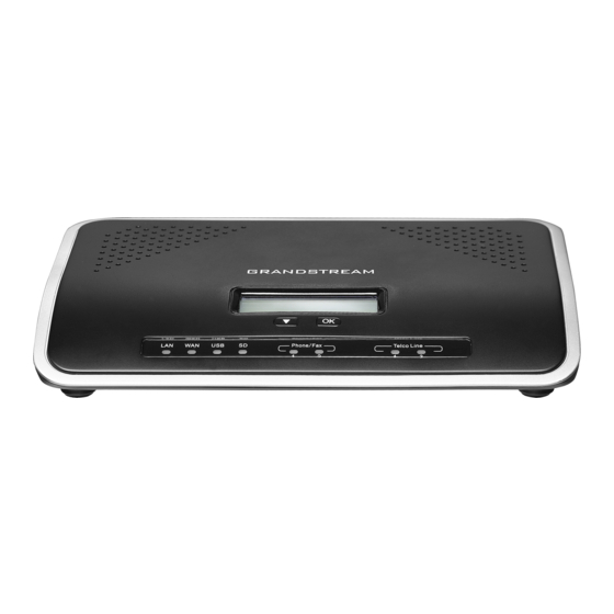
Page 5: Ucm6Xxx Setup Overview
UCM6XXX SETUP OVERVIEW To connect analog lines to UCM6xxx, please follow the below steps: • Connect the UCM6XXX to the Network via WAN/LAN Port, and power it on. • Once the UCM6XXX boots up and connects to the network, the corresponding LAN/WAN LED indicators will be in solid green and the LCD shows the IP address •... -
Page 6: Configuring Analog Trunks
CONFIGURING ANALOG TRUNKS Use a computer connected to the same network as the UCM6XXX, then login to the web GUI of the UCM6XXX by typing the IP address shown on its LCD on your browser, and type in the admin username and password. PBX Status After login, the first default page will show the UCM6XXX status, this will help users to check the FXO Ports status and give the ability to quickly see the FXO overview, without physically monitoring the FXO LEDs. -
Page 7: Create A New Analog Trunk
Create a New Analog Trunk To create a new analog trunk: 1. Go to Web GUI→PBX→Extension/Trunk→Analog Trunks. 2. Click on to add a new analog trunk. Figure 3: Create a New Analog Trunk 3. The following figure will pop up, allowing users to configure the connected analog lines to the FXO port. Figure 4: Analog Trunk Configuration Page Please refer to the following table for Analog Trunk configuration parameters. - Page 8 Table 1: Analog Trunk Configuration Parameters Select the channel where analog trunk is connected (Channel 1, Channel2…) • UCM6202/UCM6102/UCM6510: 2 channels • UCM6204/UCM6104: 4 channels FXO Port • UCM6208/UCM6108: 8 channels Note: Users can select multiple channels if the trunk is using multiple lines. Please refer to [DAHDI Out Line Selection] for more options.
- Page 9 Use CallerID Configure to enable CallerID detection. The default setting is “Yes”. Configures how faxes to this extension will be handled. None: Faxes will not be processed. Fax Mode Fax Gateway: Faxes to this extension will be processed and converted from T.30 to T.38 or vice-versa.
- Page 10 detected background noise. White Noise Injection: Injects variable amounts of white noise based on detected background noise and greatly reduces the amount of detected background noise. Allows external numbers the option to get directed to the extension that last called Direct Callback them.
-
Page 11: Create Outbound/Inbound Rules
Default value: f1=480@-50,f2=620@-50,c=250/250 Click on "Detect" to detect the busy tone, Polarity Reversal and Current Disconnect by PSTN. Before the detecting, please make sure there are more than one channel PSTN Detection configured and working properly. If the detection has busy tone, the "Tone Country" option will be set as "Custom". -
Page 12: Figure 6: Create New Inbound Rule
Figure 6: Create New Inbound Rule Once the inbound rule is created, it can be edited anytime by clicking on icon or deleted by clicking on icon. Figure 7: Inbound Rules with Time condition P a g e UCM6XXX Analog Trunks Guide... -
Page 13: Create Outbound Routes
In the above example, incoming calls during office hours will be routed to IVR, otherwise calls will be routed to extension 1000(Out Of Office hours). Figure 8: Inbound Routes Created Create Outbound Routes 1. Go to Extension / Trunk→Outbound Routes. 2. -
Page 14: Using Analog Trunk As Failover
Figure 10: Outbound Rule Created Once the outbound rule is created, it can be edited anytime by clicking on icon or deleted by clicking on icon. Using Analog Trunk as Failover Failover Trunks are used when the primary trunk fails in order to assure the continuity of external calling service for extensions. -
Page 15: Figure 11: Add Analog Trunk As Failover
Figure 11: Add Analog Trunk as Failover 5. Click on to add another failover trunk. 6. Click on to arrange the order. If there are multiple trunks set as failovers. 7. Click on to edit, or to delete the Trunk from Failover list. P a g e UCM6XXX Analog Trunks Guide... -
Page 16: Figure 12: Analog Trunk Added As Failover
Figure 12: Analog Trunk added as Failover P a g e UCM6XXX Analog Trunks Guide... -
Page 17: Acim And Pstn Detection
ACIM AND PSTN DETECTION UCM6xxx series support ACIM and PSTN detections modules allowing auto-detection and configuration of PSTN lines, this helps getting best parameters to use on PSTN lines avoiding common issues when it comes to use PSTN lines such echo, noise, calls not ended when remote party ends the call. ACIM Settings Users may sometimes face audio quality issues like noise, echo, audio volume level and choppy voice issues, this is mostly related to impedance parameters not configured correctly on the FXO ports. -
Page 18: Pstn Detection
4. Users can manually enter the ACIM settings by selecting the value from dropdown list for each port. Or users could choose the detect option (either ERL or Pr) then click on "Detect" to automatically detect the ACIM value. The detecting value will be automatically filled into the settings. Figure 14: ACIM Settings 5. -
Page 19: Figure 15: Ucm6Xxx Fxo Tone Settings
Figure 15: UCM6XXX FXO Tone Settings • If there are two analog lines connected, Auto Detect mode can be used. Detect Model: Auto Detect. Source Channel: The source channel to be detected. Destination Channel: The channel to call during auto detection. For example, the second FXO port. Destination Number: The number to be dialed for detecting. -
Page 20: Figure 17: Ucm6Xxx Pstn Detection: Semi-Auto Detect
Figure 17: UCM6XXX PSTN Detection: Semi-Auto Detect Detect Model: Semi-auto Detect. Source Channel: The source channel to be detected. Destination Number: The number to be dialed. This number could be a cell phone number or other PSTN number that can be reached from the source channel PSTN number. Dump Call Progress Tone File: Detected Call Progress Tone will be stored on a downloadable file. -
Page 21: Manual Configuration Of Pstn Parameters
Figure 19: Hangup Call Prompt 5. Once done, detected results will show in “Prompt Information” window. Click on OK to Apply changes. Figure 20: PSTN Parameters Detected Manual Configuration of PSTN Parameters If analog line tone parameters are known, customers could configure them on the UCM6xxx manually by setting Tone Country option to Custom and entering them manually. -
Page 22: Figure 21: Custom Tone Parameters
Figure 21: Custom Tone Parameters Otherwise users can manually capture an analog record trace while using the Analog Trunk, to manually measure the Busy Tone frequencies and Cadence. Please refer to steps below for capturing an analog trace record, and manually measuring Busy Tone frequencies and cadence: Step 1: Capture an Analog Record Trace 1. -
Page 23: Figure 22: Download Analog Trace
Figure 22: Download Analog Trace 5. Save the Downloaded file to a local folder on your computer, and unzip it. Note: Users can set Record Direction to Receive since we will be analyzing received file only. Another option is available to take analog record using A Key Dial-up FXO: Users can directly set a PSTN number on the “External Extension”... -
Page 24: Figure 23: A Key Dial-Up Fxo
Figure 23: A key dial-up FXO Note: When using a Key Dial-up FXO feature the outbound trunk for the analog trunk need to have internal permission. As well as it should be the trunk with the highest outbound route priority. Step 2: Import Raw File to an Audio Analyzer Software In this step we will be analyzing the Analog Record Trace using Audacity. -
Page 25: Figure 25: Import Raw Data Parameters
• Encoding to “Signed 16bit PCM” • Byte order to “No endianness” • Channels to “1 channel (Mono)” • Sample rate to “8000 Hz” Figure 25: Import Raw Data Parameters 3. The result will be similar to the following figure: Figure 26: Raw Data Imported Step 3: Measuring Cadence Once the RX raw file is successfully imported, we can now measure ringing and silence duration that will... -
Page 26: Figure 27: Measuring Cadence
Figure 27: Measuring Cadence The results are 329ms of ringing and 332 of silence, we will round them both to 330, hence the Cadence duration is c=330/330. Step 4: Measuring Busy Tone Frequencies 1. On Audacity tool bar, go to Analyze → Plot Spectrum. 2. -
Page 27: Figure 28: Busy Tone Frequencies
Figure 28: Busy Tone Frequencies In this example we have only one frequency Peak, hence the Busy tone frequencies are f1=436Hz@- 20dB and f2=0Hz@–20dB. (We have rounded the attenuation value to -20dB). P a g e UCM6XXX Analog Trunks Guide... -
Page 28: Monitoring Analog Lines
MONITORING ANALOG LINES The UCM6XXX supports SLA (Shared Line Appearance) that allows mapping the key with LED on a multi-line phone to different external lines. When there is an incoming call and the phone starts to ring, the LED on the key will flash in red and the call can be picked up by pressing this key. -
Page 29: Figure 31: Create New Sla Station
Figure 31: Create New SLA Station • Click on “Add” to add an SLA Station. • Click on to edit the SLA Station. The following table shows the SLA Station configuration parameters. • Click on to delete the SLA Station. Table 2: SLA Station Configuration Parameters Station Name Configure a name to identify the SLA Station. -
Page 30: Sample Configuration
Sample Configuration 1. Go to web UI→Extension / Trunk→Analog Trunks page. Create or edit the analog trunk. Make sure “SLA Mode” is enabled for the analog trunk. Once enabled, this analog trunk will be only available for the SLA stations created under web UI→Extension / Trunk→SLA Station page. Figure 32: Enable SLA Mode for Analog Trunk Click on “Save”. -
Page 31: Figure 35: Sla Example - Mpk Configuration
Figure 35: SLA Example - MPK Configuration Now the SLA station is ready to use. The following functions can be achieved by this configuration: • Making an outbound call from the station/extension, using LINE key When the extension is in idle state, pressing the line key for this extension on the phone to off hook. Then dial the station’s extension number, in our example, dial 3000 or 3001 on the configured Phone to hear the dial tone.