
Related Manuals for YASKAWA PS M07

Summary of Contents for YASKAWA PS M07
- Page 1 VIPA System MICRO PS | M07-2BA00 | Manual HB400 | PS | M07-2BA00 | en | 20-02 Power supply - PS M07...
- Page 2 YASKAWA Europe GmbH Ohmstraße 4 91074 Herzogenaurach Tel.: +49 9132 744 0 Fax: +49 9132 744 186 Email: info@yaskawa.eu.com Internet: www.yaskawa.eu.com M07-2BA00_000_PS M07,1,EN - © 2020...
-
Page 3: Table Of Contents
VIPA System MICRO Table of contents Table of contents General........................4 1.1 Copyright © YASKAWA Europe GmbH............4 1.2 About this manual..................... 6 1.3 Safety instructions.................... 7 Basics and mounting..................... 8 2.1 Safety information for users................8 2.2 System conception................... 9 2.3 Dimensions..................... -
Page 4: General
This material is protected by copyright laws. It may not be reproduced, distributed, or altered in any fashion by any entity (either internal or external to YASKAWA) except in accordance with applicable agreements, contracts or licensing, without the express written consent of YASKAWA and the business management owner of the material. - Page 5 Copyright © YASKAWA Europe GmbH Document support Contact your local representative of YASKAWA Europe GmbH if you have errors or ques- tions regarding the content of this document. If such a location is not available, you can reach YASKAWA Europe GmbH via the following contact: YASKAWA Europe GmbH, Ohmstraße 4, 91074 Herzogenaurach, Germany...
-
Page 6: About This Manual
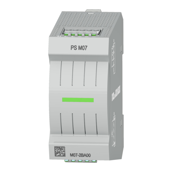
The manual describes the power supply (PS) that can be used in the VIPA System MICRO. Described are construction, application and technical data. Product Order no. as of HW state: PS M07 DC24V, 1.5A_AC120V-240V M07-2BA00 Target audience The manual is targeted at users who have a background in automation technology. Structure of the manual The manual consists of chapters. -
Page 7: Safety Instructions
VIPA System MICRO General Safety instructions 1.3 Safety instructions Warning symbol on the housing DANGER! There is a warning symbol on the housing of the power supply. This indi- cates that all safety instructions listed in this manual must be observed before commissioning! Intended use DANGER! -
Page 8: Basics And Mounting
VIPA System MICRO Basics and mounting Safety information for users Basics and mounting 2.1 Safety information for users Handling of electrostatic VIPA modules make use of highly integrated components in MOS-Technology. These sensitive modules components are extremely sensitive to over-voltages that can occur during electrostatic discharges. -
Page 9: System Conception
VIPA System MICRO Basics and mounting System conception 2.2 System conception Overview The System MICRO is a modular automation system for assembly on a 35mm mounting rail. By means of periphery modules this system may be adapted matching to your auto- mation tasks. -
Page 10: Dimensions
VIPA System MICRO Basics and mounting Dimensions Power supply The power supply is mounted on the left side from the DIN rail with the System MICRO modules. It serves for electronics and power supply. Periphery module By means of up to 8 periphery modules, you can extend the internal I/O areas. The attachment to the CPU is made by plugging them on the right side of the CPU. - Page 11 VIPA System MICRO Basics and mounting Dimensions Dimensions extension module EM M09 Dimensions in mm Dimensions power supply HB400 | PS | M07-2BA00 | en | 20-02...
-
Page 12: Mounting
VIPA System MICRO Basics and mounting Mounting Dimensions periphery module Dimensions in mm 2.4 Mounting Observe minimum distance! For operation within the specified nominal values, they must comply with a minimum distance of 30 mm on one side of the module! Dimensions in mm HB400 | PS | M07-2BA00 | en | 20-02... -
Page 13: Mounting Without Mounting Rail
VIPA System MICRO Basics and mounting Mounting > Mounting with mounting rail 2.4.1 Mounting without mounting rail Proceeding You can screw the power supply to the back wall by means of screws via the locking levers. The happens with the following proceeding: Dimensions in mm The power supply has a locking lever on the upper and lower side. - Page 14 VIPA System MICRO Basics and mounting Mounting > Mounting with mounting rail The power supply has a locking lever on the upper and lower side. Pull these levers outwards as shown in the figure, until these engage audible. CAUTION! It is not allowed to mount the module sideways on the mounting rail, as otherwise the module may be damaged.
-
Page 15: Wiring
VIPA System MICRO Basics and mounting Wiring > Wiring power supply 2.5 Wiring DANGER! Consider strain relief of the supply lines! Since the plug for the supply lines of the input voltage has no (double) insulation, not permanently fixed supply lines must be relieved from push and pull! CAUTION! Consider temperature for external cables! -
Page 16: Demounting
VIPA System MICRO Basics and mounting Demounting Insert wire The wiring happens without a tool. Determine according to the casing labelling the connection position and insert through the round connection hole of the according contact your prepared wire until it stops, so that it is fixed. ð... - Page 17 VIPA System MICRO Basics and mounting Demounting Push the screwdriver backwards: ð The connector is unlocked and can be removed. CAUTION! Via wrong operation such as pressing the screwdriver down- ward, the release lever may be damaged. In this way, remove all plugged connectors on the power supply. Power supply replacement Replacement on mounting The replacement of the power supply on the mounting rail happens with the following pro-...
- Page 18 VIPA System MICRO Basics and mounting Demounting Move the power supply on the mounting rail at its position. To fix the power supply at the mounting rail, move the locking levers back to the ini- tial position. ð The power supply is now mounted and can be wired. Plug connector Remove the connectors, which are not necessary at the power supply.
-
Page 19: Installation Guidelines
VIPA System MICRO Basics and mounting Installation guidelines 2.7 Installation guidelines General The installation guidelines contain information about the interference free deployment of a PLC system. There is the description of the ways, interference may occur in your PLC, how you can make sure the electromagnetic compatibility (EMC), and how you manage the isolation. - Page 20 VIPA System MICRO Basics and mounting Installation guidelines Proof the correct fixing of the lead isolation. – Data lines must be laid isolated. – Analog lines must be laid isolated. When transmitting signals with small ampli- tudes the one sided laying of the isolation may be favourable. –...
-
Page 21: General Data
VIPA System MICRO Basics and mounting General data 2.8 General data Conformity and approval Conformity 2014/35/EU Low-voltage directive 2014/30/EU EMC directive Approval Refer to Technical data others RoHS 2011/65/EU Restriction of the use of certain hazardous substances in electrical and electronic equipment Protection of persons and device protection Type of protection IP20... - Page 22 VIPA System MICRO Basics and mounting General data Standard Comment Overvoltage category EN 50178 UL 61010-1 Emitted interference EN 61000-6-4 Class A (Industrial area) Noise immunity EN 61000-6-2 Zone B (Industrial area) zone B EN 61000-4-2 8kV at air discharge (degree of severity 3), 6kV at contact discharge (degree of severity 3) EN 61000-4-3 HF field immunity (casing)
-
Page 23: Power Supply
VIPA System MICRO Power supply Safety instructions Power supply 3.1 Safety instructions Mounting For the power supply applies: It is mounted together with your System MICRO modules on a DIN rail. In this case, the power supply must always be mounted only on the outer edge of your System MICRO, otherwise the backplane bus is interrupted. -
Page 24: Ps M07 Dc24V, 1.5A_Ac120V-240V
VIPA System MICRO Power supply PS M07 DC24V, 1.5A_AC120V-240V 3.2 PS M07 DC24V, 1.5A_AC120V-240V Properties Output current 1.5A Rated output voltage DC 24V Connection to single-phase AC mains wide-range input AC 120...240V without manual switching Protection against short circuit and overload... - Page 25 VIPA System MICRO Power supply PS M07 DC24V, 1.5A_AC120V-240V Input AC/DC 120...240V The power supply must be supplied with AC respectively DC voltage via the input socket. A melting fuse protects the input against overload. Function Type Description L / + Input: L: AC 120...240V...
- Page 26 VIPA System MICRO Power supply PS M07 DC24V, 1.5A_AC120V-240V Operation outside the nominal values In applications according to CE approval, operation outside the nominal values is permissible, but not in applications according to UL approval! Regarding the following temperature ranges, operation outside the nominal values...
-
Page 27: Technical Data
VIPA System MICRO Power supply Technical data 3.3 Technical data Order no. M07-2BA00 Type PS M07 Module ID Technical data power supply Input voltage (rated value) AC 120...240V Input voltage (permitted range) AC 90...264 V Mains frequency (rated value) 50...60 Hz Mains frequency (permitted range) 47...63 Hz... - Page 28 VIPA System MICRO Power supply Technical data Order no. M07-2BA00 Weight including accessories 155 g Gross weight 170 g Environmental conditions Operating temperature 0 °C to 60 °C Storage temperature -40 °C to 80 °C Certifications UL certification KC certification in preparation HB400 | PS | M07-2BA00 | en | 20-02...
-
Page 29: Appendix
VIPA System MICRO Appendix Appendix HB400 | PS | M07-2BA00 | en | 20-02... - Page 30 VIPA System MICRO Appendix Content History of changes.................... 31 HB400 | PS | M07-2BA00 | en | 20-02...
-
Page 31: A History Of Changes
VIPA System MICRO History of changes History of changes Rev. Changes 20-02 The manual was created. HB400 | PS | M07-2BA00 | en | 20-02...