Table of Contents
Advertisement
Quick Links
Advertisement
Table of Contents

Related Manuals for Electro-Voice X‑LINE ADVANCE X1i


Summary of Contents for Electro-Voice X‑LINE ADVANCE X1i
- Page 1 X‑LINE ADVANCE install system rigging X1i | X2i | X12i‑128 Rigging manual...
-
Page 3: Table Of Contents
X-LINE ADVANCE install system rigging Table of contents | en Table of contents Important safety instructions Suspension Chlorine Copyright and disclaimer Symbols Declaration of conformity System overview Installation Attaching grid to top element of array Attaching elements under the top element Attaching the bottom element and bottom grid kit 3.3.1 Attaching the bottom element without a bottom grid kit... -
Page 4: Important Safety Instructions
Only use rigging components with the loudspeaker models they are designed for. Any hardware not provided by Electro-Voice is the responsibility of others. Electro-Voice assumes no liability for any damage or personal injury resulting from improper use, installation, or operation of the product. -
Page 5: Copyright And Disclaimer
X-LINE ADVANCE install system rigging Important safety instructions | en Electro-Voice offers alternate fastener kits for the grid and the rigging kit that should be specified for high chlorine environments. In such applications, these fastener kits must be used instead of the stainless steel fasteners that ship with the rigging accessories:... -
Page 6: System Overview
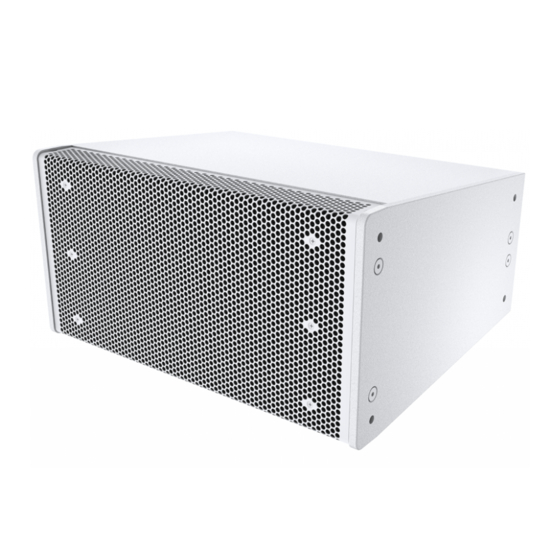
en | System overview X-LINE ADVANCE install system rigging System overview The X-Line Advance Install loudspeaker is a premium line-array loudspeaker system designed for high performance permanent install applications, such as sports arenas, houses of worship, and performing arts centers. The system represents a culmination of EV’s extensive experience in designing large format line array systems for touring applications, as well as deep knowledge in designing ruggedized install loudspeaker systems that can survive in harsh, direct exposure environments. -
Page 7: Installation
X-LINE ADVANCE install system rigging Installation | en Installation Attaching grid to top element of array Notice! A 17 mm socket, a 6 mm hex driver, a medium strength threadlocker (Loctite® 243 or equivalent) and a torque wrench are required for the installation of the line array. Warning! PREVIEW Loudspeaker Software MUST be used to design the array. - Page 8 en | Installation X-LINE ADVANCE install system rigging Orient the first enclosure as determined in PREVIEW. The element is right side up when the input cup is towards the top of the element. The element is upside down when the input cup is towards the bottom of the element.
- Page 9 X-LINE ADVANCE install system rigging Installation | en Notice! The side arms can be installed in the standard orientation (Orientation A) or in reverse orientation (Orientation B). Use the reverse orientation when the array needs to be suspended with the top element at an upward angle. Consult PREVIEW to determine whether the side arms need to be reversed to achieve the desired coverage.
- Page 10 en | Installation X-LINE ADVANCE install system rigging 18. Repeat steps 9 through 17 on the opposite side of the element. Note the orientation of the spreader bar if using a single suspension point. The spreader bar needs to be oriented differently for X1i and X2i elements to ensure that the array suspends properly.
- Page 11 X-LINE ADVANCE install system rigging Installation | en 21. Press a 12mm nylon sleeve onto the M12 shoulder bolts. 22. Apply threadlocker and insert the shoulder bolt through the grid sidearm and into the end of the spreader bar. Torque to 13.5 N*m (120 in*lbs) using a torque wrench.
- Page 12 en | Installation X-LINE ADVANCE install system rigging Warning! Do not exceed an included angle of 60° between each lift point on the spreader bars. Failure to do so may result in serious injury or death. <60º <60º 2020-06 | V03 | F01U361023 Rigging manual Bosch Security Systems B.V.
-
Page 13: Attaching Elements Under The Top Element
Only use hardware with a working load limit that exceeds the total weight of the array. Any hardware used to connect between the grid spreader bars and the venue not provided by Electro-Voice is the responsibility of others. Place the next element in the array underneath the previously assembled element. - Page 14 en | Installation X-LINE ADVANCE install system rigging Apply threadlocker and insert the 2 M10 bolts through the rear plate, the front 2 holes of the rear link bars, and the top 2 suspension points in the next element. Tighten by finger for now. Repeat step 5 on the opposite side of the element.
- Page 15 X-LINE ADVANCE install system rigging Installation | en Align the next element in the array with the previous element. The front link bars should be aligned with the top front holes in the next element. Apply threadlocker and insert the M10 bolt through the top hole of the front plate, through the link bar of the previous element and into the top front suspension point of the next element.
- Page 16 en | Installation X-LINE ADVANCE install system rigging 12. Repeat steps 9 through 11 on opposite side of element. 13. Align the rear link bar on the next element so that the bottom of the rear plate aligns with the desired splay angle.
-
Page 17: Attaching The Bottom Element And Bottom Grid Kit
X-LINE ADVANCE install system rigging Installation | en Attaching the bottom element and bottom grid kit Notice! If PREVIEW determines that a bottom grid kit is necessary, follow Attaching the bottom element without a bottom grid kit, page 17 . If PREVIEW determines that a bottom grid kit is not necessary, follow Attaching the bottom element with a bottom grid kit, page 19 . - Page 18 en | Installation X-LINE ADVANCE install system rigging Align the bottom element in the array with the previous element. The front link bars should be aligned with the top front holes in the bottom element. Apply threadlocker and insert the M10 bolt through the top hole of the front plate, through the link bar of the previous element, and into the top front suspension point of the bottom element.
-
Page 19: Attaching The Bottom Element With A Bottom Grid Kit
X-LINE ADVANCE install system rigging Installation | en 14. Torque all M10 bolts from the previous element and the bottom element to 13.5 N*m (120 in*lbs). 3.3.2 Attaching the bottom element with a bottom grid kit Follow the steps 1 through 16 in Attaching elements under the top element, page 13 , except do NOT install the front link bars on the bottom element. - Page 20 en | Installation X-LINE ADVANCE install system rigging Apply threadlocker and insert the M10 bolt through the bottom holes in the plate, through the grid side arm, and into the bottom suspension points of the bottom element. Torque to 13.5 N*m (120 in*lbs.) Repeat on the opposite side of the array.
- Page 21 X-LINE ADVANCE install system rigging Installation | en Lift the bottom of the array from the pick point hole on the spreader bar to the desired down angle of the array, as determined in PREVIEW. Warning! The pull back to venue shall not exceed 30° from vertical, 15° maximum on the top grid, and 15°...
-
Page 22: Notes
en | Notes X-LINE ADVANCE install system rigging Notes 2020-06 | V03 | F01U361023 Rigging manual Bosch Security Systems B.V. - Page 23 X-LINE ADVANCE install system rigging Notes | Bosch Security Systems B.V. Rigging manual 2020-06 | V03 | F01U361023...
- Page 24 | Notes X-LINE ADVANCE install system rigging 2020-06 | V03 | F01U361023 Rigging manual Bosch Security Systems B.V.
- Page 26 Bosch Sicherheitssysteme GmbH Bosch Security Systems, LLC Robert-Bosch-Ring 5 12000 Portland Avenue South 85630 Grasbrunn Burnsville MN 55337 Germany www.boschsecurity.com www.electrovoice.com © Bosch Sicherheitssysteme GmbH, 2020 © Bosch Security Systems, LLC, 2020...