Advertisement
Quick Links
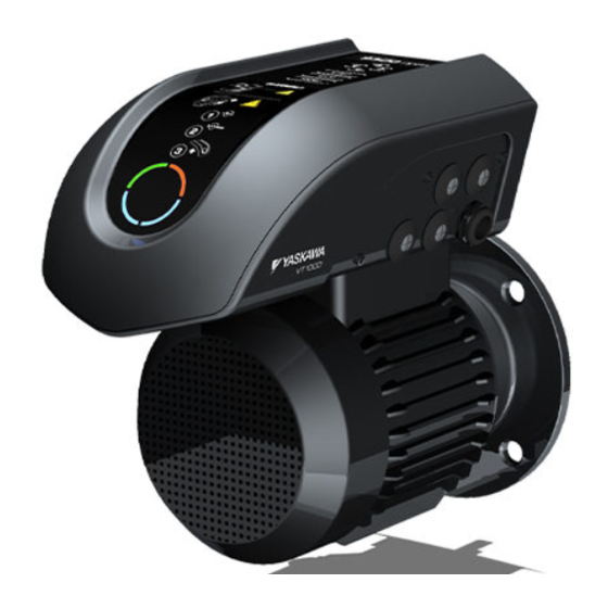
YASKAWA V1000 MMD
IP65 Motor Mounted Drive
Quick Start Guide
Type: SP-V1M
Models: 400 V Class, Three-Phase Input: 1.5 to 5.5 kW
To properly use the product, read this manual thoroughly
and retain for easy reference, inspection, and maintenance.
Ensure the end user receives this manual.
The V1000 drive in this package is equipped with a special firmware
to operate permanent magnet motors.
YASKAWA Europe TOEP C710606 101A - V1000 MMD IP65 Motor Mounted Drive - Quick Start Guide
MANUAL NO. TOEP C710606 101A
1
2
3
4
5
6
7
8
EN 1
Advertisement

Related Manuals for YASKAWA V1000 MMD


Summary of Contents for YASKAWA V1000 MMD
- Page 1 The V1000 drive in this package is equipped with a special firmware to operate permanent magnet motors. YASKAWA Europe TOEP C710606 101A - V1000 MMD IP65 Motor Mounted Drive - Quick Start Guide EN 1 MANUAL NO. TOEP C710606 101A...
- Page 2 Neither is any liability assumed for damages resulting from the use of the information contained in this publication EN 2 YASKAWA Europe TOEP C710606 101A - V1000 MMD IP65 Motor Mounted Drive - Quick Start Guide...
-
Page 3: Table Of Contents
7 Troubleshooting ......43 YASKAWA Europe TOEP C710606 101A - V1000 MMD IP65 Motor Mounted Drive - Quick Start Guide... -
Page 4: Safety Instructions And General Warnings
CAUTION Indicates a hazardous situation, which, if not avoided, could result in minor or moderate injury. NOTICE Indicates a property damage message. EN 4 YASKAWA Europe TOEP C710606 101A - V1000 MMD IP65 Motor Mounted Drive - Quick Start Guide... - Page 5 Remove all metal objects such as watches and rings, secure loose clothing, and wear eye protection before beginning work on the drive. YASKAWA Europe TOEP C710606 101A - V1000 MMD IP65 Motor Mounted Drive - Quick Start Guide EN 5...
- Page 6 CAUTION Burn Hazard • Do not touch the heatsink or braking resistor hardware until a powered-down cooling period has elapsed. EN 6 YASKAWA Europe TOEP C710606 101A - V1000 MMD IP65 Motor Mounted Drive - Quick Start Guide...
- Page 7 Using unapproved filters could result in damage to the drive or motor equipment. YASKAWA Europe TOEP C710606 101A - V1000 MMD IP65 Motor Mounted Drive - Quick Start Guide EN 7...
- Page 8 ISO 13849-1, Safety Category 3, PL d and EN61508, SIL2. Refer to the Tech- nical Manual for details about the application of this function. EN 8 YASKAWA Europe TOEP C710606 101A - V1000 MMD IP65 Motor Mounted Drive - Quick Start Guide...
-
Page 9: Mechanical Installation
• direct sunlight Altitude 1000 m or less Vibration 10 - 20 Hz at 9.8 m/s , 20 to 55 Hz at 5.9 m/s YASKAWA Europe TOEP C710606 101A - V1000 MMD IP65 Motor Mounted Drive - Quick Start Guide EN 9... - Page 10 Leave at least 50 mm distance between cable gland and next device or wall. Note: Input cable gland cable can be fitted to left or right hand side. Note: EN 10 YASKAWA Europe TOEP C710606 101A - V1000 MMD IP65 Motor Mounted Drive - Quick Start Guide...
- Page 11 1 – Inverter Drive 3 – Motor (optional) 2 – Motor Mount Collar with Screws, Sealing Grommet and Earth Wire (EUOP-V11015, optional) YASKAWA Europe TOEP C710606 101A - V1000 MMD IP65 Motor Mounted Drive - Quick Start Guide EN 11...
- Page 12 1 – Inverter Drive 2 – Wall Bracket with EMC Cable Gland, Gland Nut Mount Collar and fixing screws (EUOP- V11016, optional) EN 12 YASKAWA Europe TOEP C710606 101A - V1000 MMD IP65 Motor Mounted Drive - Quick Start Guide...
- Page 13 1. Remove the terminal lid and rubber seals from the motor and retain the 4 screws (A). A (4x) 2. Remove the terminal fixings nuts (B). B (3x) YASKAWA Europe TOEP C710606 101A - V1000 MMD IP65 Motor Mounted Drive - Quick Start Guide EN 13...
- Page 14 3. Remove the motor cables (D) from the terminal block (E) and remove terminal block (E) from the motor. 4. Fix the earth cable delivered with the collar at the motor ground terminal. EN 14 YASKAWA Europe TOEP C710606 101A - V1000 MMD IP65 Motor Mounted Drive - Quick Start Guide...
- Page 15 7. Feed the cables (D) through the rubber grommet (F) and refit it to motor mount collar. The grommet should be fitted with the flat side to the top. YASKAWA Europe TOEP C710606 101A - V1000 MMD IP65 Motor Mounted Drive - Quick Start Guide EN 15...
- Page 16 9. Lower the inverter unit (G) on to the motor mount collar and fix it using 4xM5 countersunk screws. Screws have to be torqued to 2.35 Nm. 4xM5 2.35 Nm EN 16 YASKAWA Europe TOEP C710606 101A - V1000 MMD IP65 Motor Mounted Drive - Quick Start Guide...
- Page 17 12.Feed input power cable through M20 cable gland, and wire into the filter (L1, L2, L3, PE (M5 stud)). Wire control terminals as required. YASKAWA Europe TOEP C710606 101A - V1000 MMD IP65 Motor Mounted Drive - Quick Start Guide EN 17...
- Page 18 14.Re-attach the lid (H) to the drive (G) and torque the five screws that fix the lid to 1.3 Nm. 5xM4 1.3 Nm The Drive Package is ready for use. EN 18 YASKAWA Europe TOEP C710606 101A - V1000 MMD IP65 Motor Mounted Drive - Quick Start Guide...
- Page 19 2. Fix the wall bracket to the designated area. Attach the bracket using suitable screws. M6x25 screws are recommended, screws should be torqued to 4.0 Nm. YASKAWA Europe TOEP C710606 101A - V1000 MMD IP65 Motor Mounted Drive - Quick Start Guide EN 19...
- Page 20 4. Attach the mount collar with motor cables to the wall bracket using 4-M5x20 screws. Route the cables downwards. Ø5.5 Holes to be drilled in mount collar EN 20 YASKAWA Europe TOEP C710606 101A - V1000 MMD IP65 Motor Mounted Drive - Quick Start Guide...
- Page 21 6. Attach inverter drive on to the motor mount collar and fix it using 4xM5 countersunk screws. Screws have to be torqued to 2.35 Nm. YASKAWA Europe TOEP C710606 101A - V1000 MMD IP65 Motor Mounted Drive - Quick Start Guide EN 21...
- Page 22 8. Feed the input power cable through the M25 cable gland, and wire into the filter (L1, L2, L3, PE). Wire control terminals as required. EN 22 YASKAWA Europe TOEP C710606 101A - V1000 MMD IP65 Motor Mounted Drive - Quick Start Guide...
- Page 23 10.Re-attach the lid to drive and torque the five M4 screws that fix the lid to 1.3 Nm. Ensure to re-attach cables to lid at lid. The Drive Package is ready for use. YASKAWA Europe TOEP C710606 101A - V1000 MMD IP65 Motor Mounted Drive - Quick Start Guide EN 23...
-
Page 24: Electrical Installation
115 kBps S− Symbols: Indicates a main circuit terminal. Use twisted pair cables. Use shielded twisted pair cables. Indicates a control circuit terminal. EN 24 YASKAWA Europe TOEP C710606 101A - V1000 MMD IP65 Motor Mounted Drive - Quick Start Guide... - Page 25 600 Vac, 200 kAIR 500 Vac, 200 kAIR 40004 A6T15 FWH-50B 40005 A6T20 FWH-70B 40007 A6T25 FWH-70B 40009 A6T25 FWH-90B 40011 A6T30 FWH-90B YASKAWA Europe TOEP C710606 101A - V1000 MMD IP65 Motor Mounted Drive - Quick Start Guide EN 25...
- Page 26 –To improve the power factor on the power supply side. –When using an advancing capacitor switch. –With a large capacity power supply transistor (over 600 kVA). EN 26 YASKAWA Europe TOEP C710606 101A - V1000 MMD IP65 Motor Mounted Drive - Quick Start Guide...
- Page 27 • Never share the ground wire with other devices such as welding machines, etc. • Do not loop the ground wire when using more than one drive. YASKAWA Europe TOEP C710606 101A - V1000 MMD IP65 Motor Mounted Drive - Quick Start Guide EN 27...
- Page 28 For 400 V class: Ground with 10 or less. Ground Terminal Connector is located at EMC filter (M5 screw). (2 terminals) EN 28 YASKAWA Europe TOEP C710606 101A - V1000 MMD IP65 Motor Mounted Drive - Quick Start Guide...
- Page 29 Enables or disables the internal RS422/485 comm. port terminal resistance. Used to select sourcing (PNP)/sinking (NPN, default) mode for the digital inputs (PNP requires external 24 Vdc power supply) YASKAWA Europe TOEP C710606 101A - V1000 MMD IP65 Motor Mounted Drive - Quick Start Guide EN 29...
- Page 30 Disable function is used. Refer to the Technical Manual when using this function. NOTICE! The wiring length to the terminals HC, H1 and H2 should not exceed 30 m. EN 30 YASKAWA Europe TOEP C710606 101A - V1000 MMD IP65 Motor Mounted Drive - Quick Start Guide...
-
Page 31: Keypad Operation
On: The drive is in the LOCAL mode (operation from key- LO/RE LED pad) Light Off: The drive is in REMOTE mode. YASKAWA Europe TOEP C710606 101A - V1000 MMD IP65 Motor Mounted Drive - Quick Start Guide EN 31... - Page 32 0 Flashing quickly: During deceleration at fast-stop, or during stop by interlock operation Off: During stop EN 32 YASKAWA Europe TOEP C710606 101A - V1000 MMD IP65 Motor Mounted Drive - Quick Start Guide...
- Page 33 Parameter Setting Mode drive parameters can be set up. Auto-Tuning measures the motor data for optimal performance of Auto-Tuning the drive/motor combination. YASKAWA Europe TOEP C710606 101A - V1000 MMD IP65 Motor Mounted Drive - Quick Start Guide EN 33...
-
Page 34: Start Up
Fine tune and set application parameters (e.g. PID, ...) if necessary. Final check the operation and verify the settings. Drive is ready to run the application EN 34 YASKAWA Europe TOEP C710606 101A - V1000 MMD IP65 Motor Mounted Drive - Quick Start Guide... - Page 35 C6-01 Setting [kw] Motors with 3000 rpm M071M015BM 3225 M071M022BM 3236 M071M040BM 3238 Motors with 1500 rpm M071M015BJ 3335 M080M022BJ 3336 M090L040BJ 3338 YASKAWA Europe TOEP C710606 101A - V1000 MMD IP65 Motor Mounted Drive - Quick Start Guide EN 35...
- Page 36 Use the H4- parameters to set up the output value of the analog monitor output and to adjust the output voltage levels. The default monitor value setting is “Output frequency”. EN 36 YASKAWA Europe TOEP C710606 101A - V1000 MMD IP65 Motor Mounted Drive - Quick Start Guide...
- Page 37 After taking the steps listed above, the drive should be ready to run the application and per- form the basic functions. For special setups like PID control etc. refer to the Technical Man- ual. YASKAWA Europe TOEP C710606 101A - V1000 MMD IP65 Motor Mounted Drive - Quick Start Guide EN 37...
-
Page 38: Parameter Table
• Increase this setting when speed / 1:Reverse prohibited Selection Compensa- torque oscillations occur. C4-02 tion Delay • Decrease the setting when the Time torque response is too slow. EN 38 YASKAWA EuropeTOEP C710606 101A - V1000 MMD IP65 Motor Mounted Drive - Quick Start Guide... - Page 39 Major functions are listed at the end of the table. “102” for U1-02. MP Monitor Sets the number of output pulses H6-07 Scaling when the monitor is 100% (in Hz). YASKAWA Europe TOEP C710606 101A - V1000 MMD IP65 Motor Mounted Drive - Quick Start Guide EN 39...
- Page 40 In this <1> Decrease to lower the response. Limit case set the n8-62 value to the input voltage EN 40 YASKAWA EuropeTOEP C710606 101A - V1000 MMD IP65 Motor Mounted Drive - Quick Start Guide...
- Page 41 U2-16 Motor q-Axis Current at Previous Fault (terminal P1) enabled U2-17 Motor d-Axis Current at Previous Fault 1: Open collector Output 2 (terminal P2) enabled YASKAWA Europe TOEP C710606 101A - V1000 MMD IP65 Motor Mounted Drive - Quick Start Guide EN 41...
- Page 42 Displays the bias value used to U6-20 Bias (Up/ adjust the frequency reference. Down 2) Offset Fre- Displays the frequency added to U6-21 quency the frequency reference. EN 42 YASKAWA EuropeTOEP C710606 101A - V1000 MMD IP65 Motor Mounted Drive - Quick Start Guide...
-
Page 43: Troubleshooting
Remove the cause and reset the fault. to S6. • Check the functions assigned to the digital • The digital inputs are set up incorrectly. inputs. YASKAWA Europe TOEP C710606 101A - V1000 MMD IP65 Motor Mounted Drive - Quick Start Guide EN 43... - Page 44 Cycle times of accel./ decel. are too short. • Check the sequence. Incorrect motor rated current has been set. • Check the rated current setting. EN 44 YASKAWA Europe TOEP C710606 101A - V1000 MMD IP65 Motor Mounted Drive - Quick Start Guide...
- Page 45 • Cycle power to the drive. Check if the fault Circuit Fault The charge circuit for the DC bus is broken. reoccurs. • Replace the drive if the fault reoccurs. YASKAWA Europe TOEP C710606 101A - V1000 MMD IP65 Motor Mounted Drive - Quick Start Guide EN 45...
- Page 46 • Fix any incorrect setting. control mode selected (might appear after control • Refer to the Technical Manual for more details. mode change). EN 46 YASKAWA Europe TOEP C710606 101A - V1000 MMD IP65 Motor Mounted Drive - Quick Start Guide...
- Page 47 • Increase the acceleration and deceleration times Acceleration and deceleration times are (C1-01 through C1-08). too short. • Increase the S-curve acceleration and decelera- tion times (C2-01). YASKAWA Europe TOEP C710606 101A - V1000 MMD IP65 Motor Mounted Drive - Quick Start Guide EN 47...
- Page 48 7 Troubleshooting EN 48 YASKAWA Europe TOEP C710606 101A - V1000 MMD IP65 Motor Mounted Drive - Quick Start Guide...
- Page 49 Date of original publication Date of publication Place of publication Date of Publication Rev. No. Section Revised Content January 2016 First edition YASKAWA Europe TOEP C710606 101A - V1000 MMD IP65 Motor Mounted Drive - Quick Start Guide EN 43...
- Page 50 Specifications are subject to change without notice for ongoing product modifications and improvements. © 2016 YASKAWA Europe GmbH. All rights reserved. YASKAWA Europe TOEP C710606 101A - V1000 MMD IP65 Motor Mounted Drive - Quick Start Guide EN 44 MANUAL NO. TOEP C710606 101A...