Hitachi SJ100 Series Instruction Manual
Hide thumbs
Also See for SJ100 Series:
- Instruction manual (214 pages) ,
- Service manual (75 pages) ,
- Quick reference manual (25 pages)
Table of Contents
Advertisement
Advertisement
Chapters
Table of Contents

Related Manuals for Hitachi SJ100 Series


Summary of Contents for Hitachi SJ100 Series
- Page 1 HITACHI SJ100 Series Inverter Instruction Manual • Single-phase Input 200V Class • Three-phase Input 200V Class • Three-phase Input 400V Class Manual Number: NB583XB After reading this manual, keep it handy for future reference. Hitachi, Ltd. Tokyo Japan...
- Page 2 Glossary and Bibliography In This Appendix..page — Glossary ............2 — Bibliography ............. 8...
- Page 3 Auto-tuning is a common feature of process controllers with PID loops. Hitachi inverters feature auto tuning to determine motor parameters for optimal commutation. Auto-tuning is avail- able as a special command from a digital operator panel. See also digital operator panel.
- Page 4 Digital Operator Panel For Hitachi inverters, “digital operator panel” (DOP) refers first to the operator keypad on the front panel of the inverter. It also includes hand-held remote keypads, which connect to the inverter via a cable.
- Page 5 Insulated Gate Bipolar Transistor (IGBT) - a semiconductor transistor capable of conducting very large currents when in satura- tion and capable of withstanding very high voltages when it is off. This high-power bipolar transistor is the type used in Hitachi invert- ers. Inertia The natural resistance a stationary object to being moved by an external force.
- Page 6 The ability of a motor drive to store preset discrete speed levels for the motor, and control motor speed according to the currently selected speed preset. The Hitachi inverters have 16 preset speeds. Motor Load In motor terminology, motor load consists of the inertia of the physical mass that is moved by the motor and the related friction from guiding mechanisms.
- Page 7 Hot varies sinusoidally above and below Neutral. This power source is named Single Phase to differentiate it from three-phase power sources. Some Hitachi inverters can accept single phase input power, but they all output three-phase power to the motor. See also three-phase.
- Page 8 Amperes or more, all with high reliability. The saturation voltage has been decreasing, resulting in less heat dissipation. Hitachi inverters use state-of-the-art semiconductors to provide high perfor- mance and reliability, all in a compact package. See also IGBT and saturation voltage.
- Page 9 Variable Speed Drive Fundamentals, 2nd Ed. Phipps, Clarence A. The Fairmont Press, Inc. / Prentice-Hall, Inc. 1997 ISBN 0-13-636390-3 Electronic Variable Speed Drives Brumbach, Michael E. Delmar Publishers 1997 ISBN 0-8273-6937-9 Hitachi Inverter Technical Guide Book Published by Hitachi, Ltd. Japan 1995 Publication SIG-E002...
- Page 10 Drive Parameter Settings Tables In This Appendix..page — Introduction ............2 — Parameter Settings for Keypad Entry....2 — Parameter Settings for DOP/DRW/DOP Plus .. 9...
- Page 11 Introduction Introduction This appendix lists the user-programmable parameters for the SJ100 series inverters and the default values for European and U.S. product types. The right-most column of the tables is blank, so you can record values you have changed from the default. This involves just a few parameters for most applications.
- Page 12 B–3 SJ100 Inverter Standard Functions “A” Group Parameters Default Setting User Setting Func. Code Name -FE (Europe) -FU (USA) Frequency source setting Run command source setting Base frequency setting 50.0 60.0 A203 Base frequency setting, 2nd motor 50.0 60.0 Maximum frequency setting 50.0 60.0 A204...
- Page 13 B–4 Parameter Settings for Keypad Entry “A” Group Parameters Default Setting User Setting Func. Code Name -FE (Europe) -FU (USA) Jog frequency setting Jog stop mode Torque boost method selection A241 Torque boost method selection, 2nd motor Manual torque boost value A242 Manual torque boost value, 2nd motor...
- Page 14 B–5 SJ100 Inverter “A” Group Parameters Default Setting User Setting Func. Code Name -FE (Europe) -FU (USA) Second acceleration time setting 15.0 15.0 A292 Second acceleration time setting 15.0 15.0 (2nd motor) Second deceleration time setting 15.0 15.0 A293 Second deceleration time setting 15.0 15.0 (2nd motor)
- Page 15 B–6 Parameter Settings for Keypad Entry Fine Tuning Functions “B” Group Parameters Default Setting User Setting Func. Code Name -FE (Europe) -FU (USA) Selection of restart mode Allowable under-voltage power failure time Delay before motor restart time Level of electronic thermal setting Rated current Rated current for each...
- Page 16 B–7 SJ100 Inverter Intelligent Terminal Functions “C” Group Parameters Default Setting User Setting Func. Code Name -FE (Europe) -FU (USA) Terminal 1 function Terminal 2 function Terminal 3 function Terminal 4 function Terminal 5 function Terminal 6 function Terminal 1 active state Terminal 2 active state Terminal 3 active state Terminal 4 active state...
- Page 17 B–8 Parameter Settings for Keypad Entry Sensorless Vector Functions “H” Group Parameters Default Setting User Setting Func. Code Name -FE (Europe) -FU (USA) Auto-tuning Setting Motor data selection H202 Motor data selection, 2nd motor Motor capacity Specified by Specified by the inverter the inverter capacity...
- Page 18 SJ100 Inverter Parameter Settings for DOP/DRW/DOP Plus SJ100 series inverters provide many functions and parameters which can be configured by the user. We recommend that you record all parameters which have been edited, in order to help in troubleshooting or recovery from a loss of parameter data.
- Page 19 B–10 Parameter Settings for DOP/DRW/DOP Plus Monitor Mode Setup Displayed Default Setting User Setting Func. Name -FE (Europe) -FU (USA) Code Mon. Analog voltage input ADJ-O ADJ-O adjustment Analog current input ADJ-OI ADJ-OI adjustment Analog adjustment Panel display selection PANEL PANEL Terminal monitor TERM LLL LLLLLL...
- Page 20 B–11 SJ100 Inverter Function Mode Setup Displayed Default Setting User Setting Func. Name -FE (Europe) -FU (USA) Code F-04 Control method setting CONTROL CONTROL F-05 Auto-tuning setting AUX AUTO AUX AUTO Motor date selection AUX DATA AUX DATA Motor date selection, 2AUXDATA 2AUXDATA 2nd motor...
- Page 21 B–12 Parameter Settings for DOP/DRW/DOP Plus Function Mode Setup Displayed Default Setting User Setting Func. Name -FE (Europe) -FU (USA) Code F-06 Acceleration time 1 ACC 1 0010.0s ACC 1 0010.0s Acceleration time 1, 2nd 2ACC1 0010.0s 2ACC1 0010.0s motor 2-stage acceleration time ACC CHG ACC CHG 2-stage acceleration...
- Page 22 B–13 SJ100 Inverter Function Mode Setup Displayed Default Setting User Setting Func. Name -FE (Europe) -FU (USA) Code F-11 Output frequency setting SPD FS 000.0Hz SPD FS 000.0Hz Multi-stage 1 setting SPD 1 000.0Hz SPD 1 000.0Hz Multi-speed 2 setting SPD 2 000.0Hz SPD 2 000.0Hz Multi-speed 3 setting...
- Page 23 B–14 Parameter Settings for DOP/DRW/DOP Plus Function Mode Setup Displayed Default Setting User Setting Func. Name -FE (Europe) -FU (USA) Code F-23 Electronic thermal cut- E-THM CHAR CRT E-THM CHAR CRT off characteristic Electronic thermal cut- 2E-THMCHAR CRT E-THMCHAR CRT off characteristic, 2nd motor Electronic thermal level...
- Page 24 B–15 SJ100 Inverter Function Mode Setup Displayed Default Setting User Setting Func. Name -FE (Europe) -FU (USA) Code F-32 Frequency arrival ARV ACC 000.0Hz ARV ACC 000.0Hz threshold during acceleration Frequency arrival ARV DEC 000.0Hz ARV DEC 000.0Hz threshold during deceleration F-33 Overload previous level...
- Page 25 B–16 Parameter Settings for DOP/DRW/DOP Plus Function Mode Setup Displayed Default Setting User Setting Func. Name -FE (Europe) -FU (USA) Code F-35 Intelligent output 11 OUT-TM 1 OUT-TM 1 function code Intelligent output 12 OUT-TM 2 OUT-TM 2 function code Relay output function OUT-TM RY AL OUT-TM RY AL...
- Page 26 B–17 SJ100 Inverter Function Mode Setup Displayed Default Setting User Setting Func. Name -FE (Europe) -FU (USA) Code F-50 Torque boost mode V-Boost Mode 0 V-Boost Mode 0 selection Torque boost mode 2V-Boost Mode 0 2V-Boost Mode 0 selection, 2nd motor Torque boost manual V-Boost code 11 V-Boost code 11...
- Page 27 Getting Started In This Chapter..page — Introduction ............2 — SJ100 Inverter Specifications......4 — Introduction to Variable-Frequency Drives ..7 — Frequently Asked Questions ......12...
-
Page 28: Introduction
• PID control adjusts motor speed automatically to maintain a process variable value The design in Hitachi inverters overcomes many of the traditional trade-offs between speed, torque and efficiency. The performance characteristics are: • Sensorless vector control •... - Page 29 SJ100 Inverter Inverter Specifications Label The Hitachi SJ100 inverters have product labels located on the right side of the housing, as pictured below. Be sure to verify that the specifications on the labels match your power source, motor, and application safety requirements.
-
Page 30: Sj100 Inverter Specifications
1–4 SJ100 Inverter Specifications SJ100 Inverter Specifications Model-specific tables for 200V and 400V class inverters The following three tables are specific to SJ100 inverters for the 200V and 400V class model groups. The table on page 1–6 gives the general specifications that apply to both voltage class groups. - Page 31 *5: SLV selected, set carrier frequency more than 2.1 kHz. *6: At the rated voltage when using a Hitachi standard 3-phase, 4-pole motor (when selecting high starting torque flux vector control). *7: The braking torque via capacitive feedback is the average deceleration torque at the shortest deceleration (stopping from 50/60 Hz as indicated).
- Page 32 1–6 SJ100 Inverter Specifications General Specifications The following table applies to all SJ100 inverters. Item General Specifications Protective housing *1 IP20 Control method Sine wave pulse-width modulation (PWM) control Output frequency range *4 0.5 to 360 Hz Frequency accuracy Digital command: 0.01% of the maximum frequency Analog command: 0.1% of the maximum frequency (25°C ±...
-
Page 33: Introduction To Variable-Frequency Drives
Introduction to Variable-Frequency Drives The Purpose of Motor Speed Control for Industry Hitachi inverters provide speed control for 3-phase AC induction motors. You connect AC power to the inverter, and connect the inverter to the motor. You’re probably familiar with the way a light dimmer works to vary the power sent to a light bulb, and thus the light intensity. - Page 34 1–8 Introduction to Variable-Frequency Drives An inverter, in general, is a device that converts DC power to AC power. The popular consumer power inverter is designed for powering an AC appliance from a car battery; put 12VDC in, and get 115VAC 50/60 Hz out, for example. The figure below shows how the variable-frequency drive employes an internal inverter.
- Page 35 The Hitachi inverter is a rugged and reliable device. The intention is for the inverter to assume the role of switching power to the motor during all normal operations. Therefore, this manual instructs you not to switch off power to the inverter while the motor is running (unless it is an emergency stop).
- Page 36 1–10 Introduction to Variable-Frequency Drives Intelligent Functions and Parameters Much of this manual is devoted to describing how to use inverter functions and how to config- ure inverter parameters. The inverter is micropro- cessor-controlled, and has many independent functions. The microprocessor has an on-board EEPROM for parameter storage.
- Page 37 1–11 SJ100 Inverter Velocity Profiles The SJ100 inverter is capable of sophisticated Speed speed control. A graphical representation of Fixed speed that capability will help you understand and program the associated parameters. This Accel Decel manual makes use of the velocity profile graph used in industry (shown at right).
-
Page 38: Frequently Asked Questions
Hitachi inverter. Amplifier more commonly refers to a linear amplifier for servo motor control, or a stepper motor driver IC. Finally, we use inverter to describe the Hitachi motor controller because of the way the switching electronics alternately inverts or directly couples its internal DC voltage bus to generate a variable AC output. - Page 39 For 400 V class inverters, we recommend only using a utility power source of the correct voltage. Some models of Hitachi inverters will accept either single phase or three-phase power input. How do I know which input power type to use?
- Page 40 Will I be able to add dynamic (resistive) braking to my Hitachi SJ100 drive after the initial installation? Yes. The SJ100 inverter already has a dynamic braking circuit built in. Just add the resistor sized to meet the braking requirements.
-
Page 41: Table Of Contents
Inverter Mounting and Installation In This Chapter..page — Orientation to Inverter Features ....... 2 — Basic System Description ........ 5 — Step-by-Step Basic Installation ......6 — Powerup Test ..........17 — Using the Front Panel Keypad ....... 19... -
Page 42: Orientation To Inverter Features
Main Physical Features The SJ100 Series inverters vary in size according to the current output rating and motor size for each model number. All feature the same basic keypad and connector interface for consistent ease of use. The inverter construction has a heat sink at the back of the housing. - Page 43 2–3 SJ100 Inverter 2. Second-level access - Locate the lift tab at the right lower corner of the front panel near the safety warning message. Lift the corner to swing the half-door around to the left. This exposes four more control buttons and some connectors. The FUNC., , and STR keys allow an operator to access and change the inverter’s functions and parameter values.
- Page 44 2–4 Orientation to Inverter Features 3. Third-level access - First, ensure no power source of any kind is connected to the inverter. If power has been connected, wait five minutes after powerdown and verify the Power LED is off to proceed. Then locate the recessed retention screw on the left side main front panel (it is along the left hinge area on some models, or behind...
-
Page 45: Basic System Description
2–5 SJ100 Inverter Basic System Description A motor control system will obviously include a motor and inverter, as well as fuses for safety. If you are connecting a motor to the inverter on a test bench just to get started, that’s all you may need for now. -
Page 46: Step-By-Step Basic Installation
2–6 Step-by-Step Basic Installation Step-by-Step Basic Installation This section will guide you through the following basic steps of installation: 1. Study the warnings associated with mounting the inverter. 2. Select a suitable mounting location. 3. Place covers over the inverter’s ventilation openings to prevent debris from entering. 4. - Page 47 2–7 SJ100 Inverter Step 2: To summarize the caution messages — you will need to find a solid, non- flammable, vertical surface that is a relatively clean and dry environment. In order to ensure enough room for air circulation around the inverter to aid in cooling, maintain the specified clearance around the inverter specified in the diagram.
- Page 48 2–8 Step-by-Step Basic Installation Inverter Dimensions for Mounting Step 4: Locate the applicable drawing on the following pages for your inverter. Dimensions are given in millimeters (inches) format. 67(2.64) External Dimensions MODEL H mm (in.) 93 (3.66) SJ100 002NFE 93 (3.66) -002NFU 107 (4.21) -004NFE...
- Page 49 2–9 SJ100 Inverter Dimensional drawings continued... 98(3.86) External Dimensions MODEL SJ 100 -004HFE -004HFU -007NFE -007NFU -011NFE 5(0.20) 5(0.20) 110(4.33) 4(0.16) Ground Terminal 98(3.86) MODEL SJ 100 -007HFE(No fan) -007HFU(No fan) -015HFE -015HFU -022HFE -022HFU 5(0.20) 5(0.20) 110(4.33) 4(0.16) Ground Terminal...
- Page 50 2–10 Step-by-Step Basic Installation Dimensional drawings continued... 140(5.51) SJ100 -015NFE 128(5.04) -015NFU 5(0.20) 5(0.20) Ground Terminal 140(5.51) SJ100 -022NFE -022NFU 128(5.04) -030HFE -037LFU -040HFE -040HFU 5(0.20) 5(0.20) Ground Terminal...
- Page 51 2–11 SJ100 Inverter Dimensional drawings continued... SJ100 -055LFU -055HFE -055HFU -075LFU -075HFE -075HFU 182 (7.17) 160 (6.30) 7 (0.28) 7 (0.28) Ground Terminal NOTE: Model SJ100-075LFU has (2) fans. All other models in this housing have (1) fan.
- Page 52 2–12 Step-by-Step Basic Installation Preparation for Wiring Step 5: It is very important to perform the wiring steps carefully and correctly. Before proceeding, please study the caution and warning messages below. WARNING: “Use 60/75°C Cu wire only” or equivalent. WARNING: “Open Type Equipment.” WARNING: “A Class 2 circuit wired with Class 1 wire”...
- Page 53 2–13 SJ100 Inverter Determination of Wire and Fuse Sizes The maximum motor currents in your application determines the recommended wire size. The following table gives the wire size in AWG. The “Power Lines” column applies to the inverter input power, output wires to the motor, the earth ground connection, and any other component shown in the system wiring diagram on page 2–5.
- Page 54 2–14 Step-by-Step Basic Installation Wiring the Inverter Input to a Power Supply Step 6: In this step, you will connect wiring to the input of the inverter. First, you must deter- mine whether the inverter model you have requires three-phase power only, or if it can accept either single-phase or three-phase power.
- Page 55 2–15 SJ100 Inverter CAUTION: Fasten the screws with the specified fastening torque (see the following table). Check for any loosening of screws. Otherwise, there is the danger of fire. CAUTION: Remarks for using earth leakage circuit breakers in the mains supply: Frequency inverters with CE-filters (RFI-filter) and shielded (screened) motor cables have a higher leakage current toward Earth GND.
- Page 56 2–16 Step-by-Step Basic Installation Wiring the Motor to the Inverter Output Step 7: The process of motor selection is beyond the scope of this manual. However, it must be an AC induction motor with three phases. It should also come with a chassis ground lug.
-
Page 57: Powerup Test
3. Give a brief introduction to the use of the built-in operator keypad. The powerup test gives you an important starting point to ensure a safe and successful application of the Hitachi inverter. We highly recommend performing this test before proceeding to the other chapters in this manual. - Page 58 2–18 Powerup Test CAUTION: If you operate a motor at a frequency higher than the inverter standard default setting (50Hz/60Hz), be sure to check the motor and machine specifications with the respective manufacturer. Only operate the motor at elevated frequencies after getting their approval.
-
Page 59: Using The Front Panel Keypad
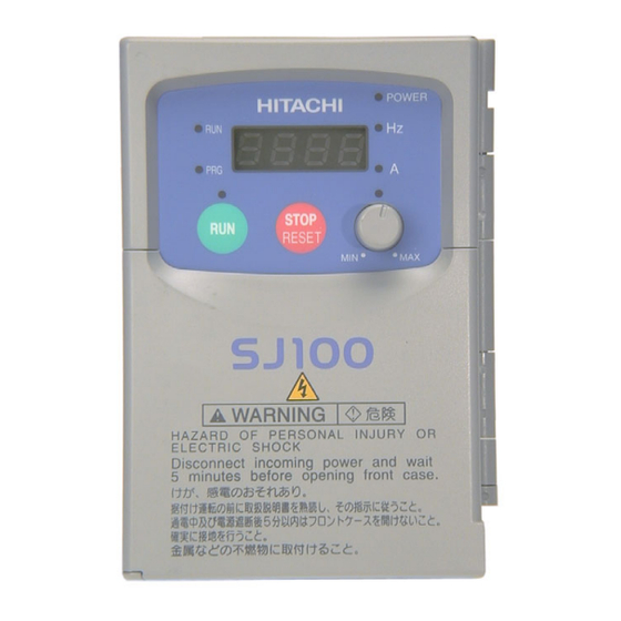
Please take a moment to familiarize yourself with the keypad layout shown in the figure below. These are the visible controls and indicators when the front panel door is closed. Parameter Display Power LED Run/Stop LED POWER HITACHI Display Units Program/Monitor LED Hertz / Amperes LEDs Potentiometer Enable LED Run Enable LED... - Page 60 • Function Key - This key is used to navigate through the lists of parameters and functions POWER for setting and monitoring parameter values. HITACHI • Up/Down ( ) Keys - Use these keys alternately to move up or down the lists of...
- Page 61 SJ100 Inverter Keypad Navigational Map The SJ100 Series inverter drives have many programmable functions and parameters. Chapter 3 will cover these in detail, but we need to access just a few items to perform the powerup test. The menu structure makes use of function codes and parameter codes to allow programming and monitoring with only a 4-digit display and a few buttons and LEDs.
- Page 62 2–22 Using the Front Panel Keypad Selecting Functions and Editing Parameters In order to run the motor for the powerup test, this section will show how to: • select the inverter’s maximum output frequency to the motor • select the keypad potentiometer as the source of motor speed command •...
- Page 63 2–23 SJ100 Inverter Select the Potentiometer for Speed Command - the motor speed may be controlled from the following sources: • Potentiometer on front panel keypad • Control terminals • Remote panel Then follow the steps in the table below to select the potentiometer for the speed command (the table resumes action from the end of the previous table).
- Page 64 2–24 Using the Front Panel Keypad Configure the Inverter for the Number of Motor Poles- the number of magnetic poles of a motor is determined by the motor’s internal winding arrangement. The specifica- tions label on the motor usually indicates its number of poles. For proper operation, verify the parameter setting matches the motor poles.
- Page 65 After using the keypad for parameter editing, it’s a good idea to switch the inverter from POWER HITACHI Program Mode to Monitor Mode and close the panel door (puts the keys for parameter editing out of sight). This will also turn out...
- Page 66 NOTE: Some factory automation devices such as PLCs have alternate Run/Program modes; the device is in either one mode or the other. In the Hitachi inverter, however, Run Mode alternates with Stop Mode, and Program Mode alternates with Monitor Mode.
- Page 67 Configuring Drive Parameters In This Chapter..page — Choosing a Programming Device ....2 — Using Keypad Devices ........3 — Using the PC Software — DOP Plus ....6 — “D” Group: Monitoring Functions...... 8 — “F” Group: Main Profile Parameters ....9 —...
-
Page 68: Choosing A Programming Device
Therefore, it is OK to begin running the motor with a loosely tuned system. By making specific, individual changes and observing their effects, you can achieve a finely tuned system. And, the SJ100 Series inverters have a built-in auto-tuning algorithm to set certain motor parameters. -
Page 69: Using Keypad Devices
Using Keypad Devices Inverter Font Panel Keypad The SJ100 Series inverter front keypad contains all the elements for both monitoring and programming parameters. The keypad layout is pictured below. All other programming devices for the inverter have a similar key arrangement and function. The DOP Plus PC software has an on-screen keypad as well. - Page 70 3–4 Using Keypad Devices Keypad Navigational Map Whether you use the keypad on the inverter, the DOP software for the personal computer, or the hand-held digital operator panel, each navigates the same way. The diagram below shows the basic navigational map of parameters and functions. Monitor Mode Program Mode PRG LED = OFF...
- Page 71 The DRW-0EA2 Copy Unit lets you read the parameters from one unit and copy them to another. The Operator Monitor can view (but not edit) parameters. See Appendix B for DOP monitor and function tables. Contact your local Hitachi distributor for more product information.
-
Page 72: Using The Pc Software - Dop Plus
Using the PC Software — DOP Plus During application development, using the DOP Plus software is a great way to configure your inverter. This package works with several Hitachi inverter families, providing these features: • Automatic detection of inverter family • Save parameter settings to disk •... - Page 73 3–7 SJ100 Inverter Programming with the DOP Plus The screen arrangement is similar to the inverter keypad. Additional buttons Read EEPROM and Write EEPROM let you upload or download parameter settings. After doing a Read EEPROM, all the inverter’s parameter settings will be accessi- ble in the scrollable list box.
-
Page 74: D" Group: Monitoring Functions
3–8 “D” Group: Monitoring Functions “D” Group: Monitoring Functions Parameter Monitoring Functions You can access important system parameter values with the “D” group monitoring functions, whether the inverter is in Run Mode or Stop Mode. After selecting the function code number for the parameter you want to monitor, press the Function key once to show the value on the display. -
Page 75: F" Group: Main Profile Parameters
3–9 SJ100 Inverter Trip Event and History Monitoring The trip event and history monitoring feature lets you cycle through related information using the keypad. More details about trip event monitoring are on page 6–5. “D” Function DOP,DRW,DOP+ Run- Range time Func. -
Page 76: A" Group: Standard Functions
3–10 “A” Group: Standard Functions “A” Group: Standard Functions Basic Parameter Settings These settings affect the most fundamental behavior of the inverter — the outputs to the motor. The frequency of the inverter’s AC output determines the motor speed. You may select from three different sources for the reference speed. - Page 77 3–11 SJ100 Inverter “A” Function Defaults DOP,DRW,DOP+ Run- time Func. Func. Name Description Units Name Edit Code Code ✘ Maximum frequency Settable from the base 50/60 F-01 F-MAX setting frequency up to 360 Hz ✘ A204 Maximum frequency Settable from the base 50/60 F-01 2F-MAX...
- Page 78 3–12 “A” Group: Standard Functions “A” Function Defaults DOP,DRW,DOP+ Run- time Func. Func. Name Description Units Name Edit Code Code ✘ External frequency Two options; select codes: — F-31 offset enable 00 ...Use offset (A11 value) LEVEL 01 ...Use 0 Hz ✘...
- Page 79 3–13 SJ100 Inverter V/F Characteristics When the motor load has a lot of inertia or A42 = 11 starting friction, you may need to increase 100% Torque boost the low frequency starting torque charac- teristics by boosting the voltage above the 11.8% normal V/F ratio (shown at right).
- Page 80 3–14 “A” Group: Standard Functions NOTE: When the inverter is in SLV (sensorless vector) mode, use B83 to set the carrier frequency greater than 2.1 kHz for proper operation. When the data of the H Group parameters does not match that of the motor, satisfactory characteristics may not be obtained during sensorless vector operation.
- Page 81 3–15 SJ100 Inverter DC Braking Settings The DC braking feature provides additional stopping power when compared to just a normal deceleration to a stop. DC Running Free run DC braking braking is particularly useful at the low frequency end of the deceleration ramp where there is little or no motor torque time available for stopping.
- Page 82 3–16 “A” Group: Standard Functions Frequency-related Functions The inverter output generates a variable-frequency waveform that determines the motor speed (minus slip losses). You can configure the lower frequency limit to be greater than zero as shown in the graph (below left). The upper limit must not exceed the rating of the motor or capability of the machinery.
- Page 83 3–17 SJ100 Inverter PID Control When enabled, the built-in PID loop calculates an ideal inverter output value to cause a loop feedback process variable (PV) to move closer in value to the setpoint (SP). The current frequency command serves as the SP. The PID loop calculations will read the analog input for the process variable (you specify the current or voltage input) and calcu- late the output.
- Page 84 3–18 “A” Group: Standard Functions Automatic Voltage Regulation (AVR) Function The automatic voltage regulation (AVR) feature keeps the inverter output waveform at a relatively constant amplitude during power input fluctuations. This can be useful if the installation has an erratic power source. However, the inverter cannot boost its motor output to a voltage higher than the power input voltage.
- Page 85 3–19 SJ100 Inverter Second Acceleration and Deceleration Functions The SJ100 inverter features two-stage acceleration and deceleration ramps. This gives flexibility in the profile shape, and can avoid jerk (mechanical shock) while approaching steady frequency (or stop) more gently. You can specify the frequency transition point, the point at which the standard acceleration (F02) or deceleration (F03) changes to the second acceleration (A92) or deceleration (A93).
- Page 86 3–20 “A” Group: Standard Functions “A” Function Defaults DOP,DRW,DOP+ Run- time Func. Func. Name Description Units Name Edit Code Code ✘ Select method to use Two options for switching — F-06 second accel/decel from 1st to 2nd accel/decel: 00 ...2CH input from terminal 01 ...transition frequency ✘...
-
Page 87: B" Group: Fine Tuning Functions
3–21 SJ100 Inverter “B” Group: Fine Tuning Functions The “B” group of functions and parameters adjust some of the more subtle but useful aspects of motor control and system configuration. Restart Mode The restart mode determines how the Input inverter will resume operation after a fault power failure causes a trip event. - Page 88 3–22 “B” Group: Fine Tuning Functions Electronic Thermal Overload Alarm Setting The thermal overload detection protects Torque Constant torque B13 = 01 the inverter and motor from excessive heat. 100% First use B13 to select the torque charac- Reduced teristic as a function of frequency. For torque example, a motor can overheat if it runs for B13 = 00...
- Page 89 3–23 SJ100 Inverter Overload Restriction When the inverter output current exceeds a restriction area Motor preset current level you specify, the Current overload restriction feature arbitrarily reduces the output current. This feature does not generate an alarm or trip event. You can instruct the inverter to apply Output frequency...
- Page 90 3–24 “B” Group: Fine Tuning Functions Software Lock Mode The software lock function keeps personnel from accidentally changing parameters in the inverter memory. The feature has some options, but the software lock function (B21) is not protected from operator editing. You can lock all other parameters except the output frequency (F01), if desired.
- Page 91 3–25 SJ100 Inverter Miscellaneous Settings The miscellaneous settings include scaling factors, initialization modes, and others. Here we will cover some of the most important settings you may need to configure. B83: Carrier frequency adjustment – the internal switching frequency of the inverter circuitry (also called the chopper frequency).
- Page 92 3–26 “B” Group: Fine Tuning Functions “B” Function Defaults DOP,DRW,DOP+ Run- time Func. Func. Name Description Units Name Edit Code Code ✔ Analog frequency Adjust 8-bit gain to analog — Mon. meter adjustment meter connected to terminal FM, range is 0 to 255 ✘...
- Page 93 3–27 SJ100 Inverter “B” Function Defaults DOP,DRW,DOP+ Run- time Func. Func. Name Description Units Name Edit Code Code ✔ Data select for digital Select the monitoring data to — Mon. PANEL operator OPE-J send to the hand-held digital operator, seven option codes: 01...
-
Page 94: C" Group: Intelligent Terminal Functions
3–28 “C” Group: Intelligent Terminal Functions “C” Group: Intelligent Terminal Functions The six input terminals 1, 2, 3, 4, 5, and 6 can be configured for any of 19 different functions. The next two tables show how to configure the six terminals. The inputs are logical, in that they are either OFF or ON. - Page 95 3–29 SJ100 Inverter The input logic convention is programmable for each of the six inputs. Most inputs default to normally open (active high), but you can select normally closed (active low) in order to invert the sense of the logic. “C”...
- Page 96 3–30 “C” Group: Intelligent Terminal Functions Summary Table - this table shows all nineteen intelligent input functions at a glance. Detailed descriptions of these functions, related parameters and settings, and example wiring diagrams are in Chapter 4, starting on page 4–6. Input Function Summary Table Option Terminal...
- Page 97 3–31 SJ100 Inverter Input Function Summary Table Option Terminal Function Name Description Code Symbol External Trip When assigned input transitions Off to On, inverter latches trip event and displays E12 No trip event for On to Off, any recorded trip events remain in history until Reset On powerup, the inverter will not resume a Unattended Start...
- Page 98 3–32 “C” Group: Intelligent Terminal Functions Output Terminal Configuration The inverter provides configuration for logic (discrete) and analog outputs, shown in the table below. “C” Function Defaults DOP,DRW,DOP+ Run- time Func. Func. Name Description Units Name Edit Code Code ✘ Terminal 11 function Select function for terminal 11, —...
- Page 99 3–33 SJ100 Inverter Output Summary Table - this table shows all six functions for the logical outputs (11, 12) at a glance. Detailed descriptions of these functions, related parameters and settings, and example wiring diagrams are in Chapter 4, starting on page 4–21. Output Function Summary Table Option Terminal...
- Page 100 3–34 “C” Group: Intelligent Terminal Functions Output Function Adjustment Parameters The overload level parameter (C41)sets the Motor motor current level at which the overload current signal becomes true. The range of settings is from 0% to 200% of the rated current Overload for the inverter.
- Page 101 3–35 SJ100 Inverter “C” Function Defaults DOP,DRW,DOP+ Run- time Func. Func. Name Description Units Name Edit Code Code ✘ Analog meter adjust- Scale factor between the — Mon. ADJ-O ment, voltage input external frequency command on terminals L – O (voltage input) and the frequency output ✘...
-
Page 102: H" Group: Sensorless Vector Functions
3–36 “H” Group: Sensorless Vector Functions “H” Group: Sensorless Vector Functions The “H” group parameters configure the Inverter PWM Switching Algorithms inverter for the motor characteristics. You Variable freq. control, must manually set H03 and H04 values to constant torque match the motor. - Page 103 3–37 SJ100 Inverter “H” Function Defaults DOP,DRW,DOP+ Run- time Func. Func. Name Description Units Name Edit Code Code ✘ Motor constant Kp Motor proportional gain — F-05 AUX Kp constant (factory set), range is 0 to 99 ✘ H205 Motor constant Kp, Motor proportional gain —...
- Page 104 3–38 “H” Group: Sensorless Vector Functions “H” Function Defaults DOP,DRW,DOP+ Run- time Func. Func. Name Description Units Name Edit Code Code ✘ Motor constant R2 Auto-tuning data (do not edit) factory — — — ✘ factory H231 Motor constant R2, Auto-tuning data (do not edit) —...
- Page 105 Operations and Monitoring In This Chapter..page — Introduction ............2 — Connecting to PLCs and Other Devices ..4 — Using Intelligent Input Terminals ...... 6 — Using Intelligent Output Terminals ....21 — Analog Input Operation ........27 —...
-
Page 106: Introduction
4–2 Introduction Introduction The previous chapter gave a reference listing of all the programmable functions of the inverter. We suggest that you first scan through the previous chapter’s listing of inverter functions to gain a general familiarity. This chapter will build on that knowledge in the following ways: 1. - Page 107 4–3 SJ100 Inverter Warning Messages for Operating Procedures WARNING: Be sure to turn on the input power supply after closing the front case. While being energized, be sure not to open the front case. Otherwise, there is the danger of electric shock. WARNING: Be sure not to operate the switches with wet hands.
-
Page 108: Connecting To Plcs And Other Devices
Connecting to PLCs and Other Devices Connecting to PLCs and Other Devices Hitachi inverters (drives) are useful in many types of applications. During installation, the inverter keypad (or other programming device) will facilitate the initial configura- tion. After installation, the inverter will generally receive its control commands through the control logic connector or serial interface from another controlling device. - Page 109 4–5 SJ100 Inverter Specifications of Control and Logic Connections The control logic connectors are located just behind the front panel half-door. The relay contacts are accessible behind the main door. Connector labeling is shown below. Logic AL0 AL1 AL2 inputs Relay contacts Analog...
-
Page 110: Using Intelligent Input Terminals
4–6 Using Intelligent Input Terminals Using Intelligent Input Terminals Terminals 1, 2, 3, 4, 5, and 6 are identical, Inverter programmable inputs for general use. The 24VDC input circuits can use the inverter’s internal – (isolated) +24V field supply (P24) to power the inputs. - Page 111 4–7 SJ100 Inverter Multi-Speed Select The inverter provides storage parameters for up to 16 different target frequencies (speeds) that the Input Function Multi- motor output uses for steady-state run condition. speed These speeds are accessible through programming four of the intelligent terminals as binary-encoded Speed 1 inputs CF1 to CF4 per the table below.
- Page 112 4–8 Using Intelligent Input Terminals Input Option Terminal Description Function Name Code Symbol State C01, C02, C03, C04, C05, C06 Valid for inputs: Example: (MSB) (LSB) Required settings: F01, A20 to A35 CF4 CF3 CF2 CF1 Notes: • When programming the multi-speed settings, be sure to press the Store key each time and then set the next multi-speed setting.
- Page 113 4–9 SJ100 Inverter Jogging Command When the terminal [JG] is turned on and the [JG] Run command is issued, the inverter outputs terminal the programmed jog frequency to the motor. [FW, RV] Use a switch between terminals [JG] and (Run) [P24] to activate the JG frequency.
- Page 114 4–10 Using Intelligent Input Terminals External Signal for DC Braking When the terminal [DB] is turned on, the DC Scenario 1 braking [DB] feature is enabled. Set the [FW, RV] following parameters when the external DC (Run terminal) braking terminal is to be used: [DB] terminal 1.
- Page 115 4–11 SJ100 Inverter Set Second Motor If you assign the [SET] function to a logic terminal, the inverter will display the x2xx numbered parameters, allowing you to edit the second motor parameters. These parame- ters store an alternate set of motor characteristic parameters. When the terminal [SET] is turned On, the inverter will use the second set of parameters to generate the frequency output to the motor.
- Page 116 4–12 Using Intelligent Input Terminals Two-stage Acceleration and Deceleration When terminal [2CH] is turned on, the Output inverter changes the rate of acceleration and frequency target frequency deceleration from the initial settings (F02 and second F03) to use the second set of acceleration/ initial deceleration values.
- Page 117 4–13 SJ100 Inverter Free-run Stop When the terminal [FRS] is turned on, the inverter stops the output and the motor enters the free-run state (coasting). If terminal [FRS] is turned off, the output resumes sending power to the motor if the Run command is still active. The free-run stop feature works with other parameters to provide flexibility in stopping and starting motor rotation.
- Page 118 4–14 Using Intelligent Input Terminals External Trip When the terminal [EXT] is turned on, the inverter enters the trip state, indicates error code E12, and stops the output. This is a general purpose interrupt type feature, and the meaning of the error depends on what you connect to the [EXT] terminal. When the switch between the set terminals [EXT] and [P24] is turned on, the equipment enters the trip state.
- Page 119 4–15 SJ100 Inverter Unattended Start Protection If the Run command is already set when power is turned on, the inverter starts running immediately after powerup. The Unattended Start Protection (USP) function prevents that automatic startup, so that the inverter will not run without outside intervention. To reset an alarm and restart running, turn the Run command off or perform a reset opera- tion by the terminal [RS] input or the keypad Stop/reset key.
- Page 120 4–16 Using Intelligent Input Terminals Software Lock When the terminal [SFT] is turned on, the data of all the parameters and functions except the output frequency is locked (prohibited from editing). When the data is locked, the keypad keys cannot edit inverter parameters. To edit parameters again, turn off the [SFT] terminal input.
- Page 121 4–17 SJ100 Inverter Analog Input Current/Voltage Select The [AT] terminal selects whether the inverter uses the voltage [O] or current [OI] input terminals for external frequency control. When the switch between the terminals [AT] and [P24] is on, it is possible to set the output frequency by applying a current input signal at [OI]-[L].
- Page 122 4–18 Using Intelligent Input Terminals Reset Inverter The [RS] terminal causes the inverter to 12 ms minimum execute the reset operation. If the inverter is [RS] terminal in Trip Mode, the reset cancels the Trip state. approx. 30 ms When the switch between the set terminals [RS] and [P24] is turned on and off, the Alarm output inverter executes the reset operation.
- Page 123 4–19 SJ100 Inverter PTC Thermistor Thermal Protection Motors that are equipped with a thermistor can be protected from overheating. Input terminal 5 has the unique ability to sense a thermistor voltage. When the resistance value of the thermistor connected to terminal [PTC] (5) and [L] is more than 3 k Ohms ± 10%, the inverter enters the Trip Mode, turns off the output to the motor, and indicates the trip status E35.
- Page 124 4–20 Using Intelligent Input Terminals Remote Control Up and Down Functions The [UP] [DWN] terminal functions can adjust the output frequency for remote control while the motor is running. The acceleration time and deceleration time of this function is same as normal operation ACC1 and DEC1 (2ACC1,2DEC1). The input terminals operate according to these principles: •...
-
Page 125: Using Intelligent Output Terminals
4–21 SJ100 Inverter Using Intelligent Output Terminals The intelligent output terminals are programmable in a similar way to the intelligent input terminals. The inverter has several output functions which you can assign individu- ally to three physical logic outputs. Two of the outputs are open-collector transistors, and the third output is the alarm relay (form C –... - Page 126 4–22 Using Intelligent Output Terminals Frequency Arrival Signal Frequency Arrival [FA1] and [FA2] signals indicate when the output frequency acceler- ates or decelerates to arrive at a constant frequency. Refer to the figure below. Frequency Arrival [FA1] (left graph) turns on when the output frequency gets within 0.5 Hz below or 1.5 Hz above the target constant frequency.
- Page 127 4–23 SJ100 Inverter Overload Advance Notice Signal When the output current exceeds a preset Current threshold value, the [OL] terminal signal turns on. power running The parameter C41 sets the overload threshold. The overload detection circuit value regeneration operates during powered motor operation threshold and during regenerative braking.
- Page 128 4–24 Using Intelligent Output Terminals Output Deviation for PID Control Error The PID loop error is defined as the Process variable (SP-PV) magnitude (absolute value) of the differ- ence between the Setpoint (target value) Setpoint and the Process Variable (actual value). value When the error magnitude exceeds the preset value for C44, the [OD] terminal...
- Page 129 4–25 SJ100 Inverter Alarm Signal The inverter alarm signal is active when a fault has STOP STOP STOP STOP occurred and it is in the Trip Mode (refer to the RESET Stop diagram at right). When the fault is cleared the alarm signal becomes inactive.
- Page 130 4–26 Using Intelligent Output Terminals The alarm output terminals are connected as shown below (left) by default, or after initialization. The contact logic can be inverted as shown (below right) by using the parameter setting C33. The relay contacts normally open (N.O.) and normally closed (N.O.) convention uses “normal”...
-
Page 131: Analog Input Operation
4–27 SJ100 Inverter Analog Input Operation The SJ100 inverters provide for analog input to command the inverter frequency output +V Ref. value. The analog input terminal group includes the L, OI, O, and H terminals on the Voltage input control connector, which provide for Voltage Current input [O] or Current [OI] input. -
Page 132: Analog And Digital Monitor Output
4–28 Analog and Digital Monitor Output Analog and Digital Monitor Output In the system design for the inverter application, it is useful to monitor the inverter operation from a remote location. In some cases, this is only a panel-mounted analog meter (moving-coil type). - Page 133 4–29 SJ100 Inverter Current Monitor, PWM Signal – (C23 = 01) – The [FM] output duty cycle varies with the inverter output current to the motor. The signal period T is fixed at 4 ms, and the amplitude is fixed at 10 VDC. The signal on [FM] reaches full scale when the inverter output current reaches 200% of the rated inverter current.
-
Page 134: Auto-Tuning For Sensorless Vector Control
4–30 Auto-tuning for Sensorless Vector Control Auto-tuning for Sensorless Vector Control The SJ100 inverter has a built-in auto-tuning algorithm. Its purpose is to detect and record the motor parameters to use in sensorless vector control. As you may recall from Chapter 3, sensorless vector control (SLV) is the more sophisticated control algorithm the SJ100 inverter can use to deliver higher torque levels at different speeds. - Page 135 4–31 SJ100 Inverter Parameter Step Parameter Setting or Action Notes Code Name A82 AVR voltage select Select output voltage for motor Voltage setting cannot be greater 200V class: 200/220/230/240 than input voltage 400V class: 380/400/415/440/ A51 DC braking enable Set = 00 to disable DC braking Default = 00 (disabled) H01 Auto-tuning Set = 01 (full auto-tuning Try using H01 = 01, if possible.
- Page 136 4–32 Auto-tuning for Sensorless Vector Control If the desired characteristic cannot be obtained in sensorless vector controlled operation with standard (factory default) or auto-tuning data, adjust the motor constant(s) according to the observed symptoms shown below. Operation Status Symptom Adjustment Parameter Powered running When low frequency (a few...
-
Page 137: Pid Loop Operation
4–33 SJ100 Inverter PID Loop Operation In standard operation, the inverter uses a reference source selected by parameter A01 for the output frequency, which may be a fixed value (F01), a variable set by the front panel potentiometer, or value from an analog input (voltage or current). To enable PID opera- tion, set A71 = 01. -
Page 138: Configuring The Inverter For Multiple Motors
4–34 Configuring the Inverter for Multiple Motors Configuring the Inverter for Multiple Motors Simultaneous Connections For some applications, you may need to connect two U/T1 or more motors (wired in parallel) to a single V/T2 Inverter Motor 1 W/T3 inverter’s output. For example, this is common in conveyor applications where two separate conveyors need to have approximately the same speed. - Page 139 4–35 SJ100 Inverter Parameters for the second motor have a function code of the form x2xx. They appear immediately after the first motor’s parameter in the menu listing order. The following table lists the parameters which have the second parameter register for programming. Parameter Codes Function Name 1st motor...
- Page 140 Motor Control Accessories In This Chapter..page — Introduction ............2 — Component Descriptions........3...
- Page 141 RF noise NOTE: The Hitachi part number series for filter accessories includes different sizes of each part type, specified by the –x suffix. Hitachi product AC reactor, or literature can help match size and rating of the LCR filter your inverter to the proper accessory size.
- Page 142 5–3 SJ100 Inverter Component Descriptions AC Reactors, Input Side This is useful in suppressing harmonics induced on the power supply lines, or when the main power voltage imbalance exceeds 3% (and power source capacity is more than 500 kVA), or to smooth out line fluctuations. It also improves the power factor. In the following cases for a general-purpose inverter, a large peak current flows on the main power supply side, and is able to destroy the inverter module: •...
- Page 143 5–4 Component Descriptions RF Noise Filters (Magnetic Choke) Electrical noise interference may occur on nearby equipment such as a radio receiver. This magnetic choke filter helps reduce radiated noise from the inverter wiring. It can be used on the input or output side of the inverter.
- Page 144 5–5 SJ100 Inverter Dynamic Braking The purpose of dynamic braking is to improve the ability of the inverter to stop (decelerate) the motor and load. This becomes neces- sary when an application has some or all of the following factors: •...
- Page 145 Troubleshooting and Maintenance In This Chapter..page — Troubleshooting..........2 — Monitoring Trip Events, History, & Conditions .. 5 — Restoring Factory Default Settings ....8 — Maintenance and Inspection ......9 — Warranty............14...
-
Page 146: Troubleshooting
6–2 Troubleshooting Troubleshooting Safety Messages Please read the following safety messages before troubleshooting or performing mainte- nance on the inverter and motor system. WARNING: Wait at least five (5) minutes after turning off the input power supply before performing maintenance or an inspection. Otherwise, there is the danger of electric shock. - Page 147 6–3 SJ100 Inverter Troubleshooting Tips The table below lists typical symptoms and the corresponding solution(s). Symptom/condition Probable Cause Solution • • Is the frequency command source Make sure the parameter A01 parameter setting correct? setting A01 is correct. • • Is the Run command source A02 Make sure the parameter parameter setting correct?
- Page 148 6–4 Troubleshooting Symptom/condition Probable Cause Solution • • If using the analog input, is the Check the wiring. current or voltage at “O” or “OI?” • Check the potentiometer or signal generating device. The motor speed will not reach the target frequency (desired •...
-
Page 149: Monitoring Trip Events, History, & Conditions
6–5 SJ100 Inverter Monitoring Trip Events, History, & Conditions Inverter Fault Detection The microprocessor in the inverter detects a variety STOP STOP STOP STOP of fault conditions and latches the event, recording RESET Stop it in a history table. The inverter output turns off, or “trips”... - Page 150 6–6 Monitoring Trip Events, History, & Conditions Error Codes An error code will appear on the display automatically when a fault causes the inverter to trip. The following table lists the cause associated with the error. Error Name Cause(s) Code Over current event while The inverter output was short-circuited, or the motor at constant speed...
- Page 151 6–7 SJ100 Inverter Error Name Cause(s) Code Ground fault The inverter is protected by the detection of ground faults between the inverter output and the motor upon during powerup tests. This feature protects the inverter, and does not protect humans. Input over-voltage When the input voltage is higher than the specified value, it is detected 100 seconds after powerup and...
-
Page 152: Restoring Factory Default Settings
6–8 Restoring Factory Default Settings Restoring Factory Default Settings You can restore all inverter parameters to the original factory (default) settings, for the intended country of use. After initializing the inverter, use the powerup test in Chapter 2 to get the motor running again. To initialize the inverter, follow the steps below. 1. -
Page 153: Maintenance And Inspection
6–9 SJ100 Inverter Maintenance and Inspection Monthly and Yearly Inspection Chart Inspection Inspection Cycle Item Inspected Check for... Criteria Method Month Year ✔ Overall Ambient Extreme Thermometer, Ambient temperature environment temperatures hygrometer between -10 to 40°C, & humidity non-condensing ✔ Major devices Abnormal Visual and aural... - Page 154 6–10 Maintenance and Inspection Spare parts We recommend that you stock spare parts to reduce down time, which include: Quantity Part description Symbol Notes Used Spare Cooling fan 022NF, 030HF, 037LF, 015HF to 075HF Case Front case Key cover Case Bottom cover Capacitor Life Curve The DC bus inside the inverter uses a large capacitor as shown in the diagram below.
- Page 155 6–11 SJ100 Inverter General Inverter Electrical Measurements The following table specifies how to measure key system electrical parameters. The diagrams on the next page show inverter-motor systems and the location of measurement points for these parameters. Circuit location Measuring Parameter Notes Reference Value of measurement...
- Page 156 6–12 Maintenance and Inspection The figures below show measurement locations for voltage, current, and power measure- ments listed in the table on the previous page. The voltage to be measured is the funda- mental wave effective voltage. The power to be measured is the total effective power. Single-phase measurement diagram U/T1 INVERTER...
- Page 157 6–13 SJ100 Inverter Inverter Output Voltage Measurement Techniques Taking voltage measurements around drives equipment requires the right equipment and a safe approach. You are working with high voltages and high-frequency switching waveforms that are not pure sinusoids. Digital voltmeters will not usually produce reliable readings for these waveforms.
-
Page 158: Warranty
2. When service is required for the product at your work site, all expenses associated with field repair shall be charged to the purchaser. 3. Always keep this manual handy; please do not loose it. Please contact your Hitachi distributor to purchase replacement or additional manuals. - Page 159 SJ100 Inverter Revisions Revision History Table Operation Revision Comments Date of Issue Manual No. Initial release of manual NB583X April 1999 NB583X Revision A May 1999 NB583XA Added 7.5 and 10 HP models to tables and drawings in Chapters 1 and 2, made minor typographical or technical corrections throughout manual Revision B August 1999...