Aiphone IX Series Installation & Programming Manual
2-wire network adaptor
Hide thumbs
Also See for IX Series:
- Operation manual (234 pages) ,
- Web setting manual (157 pages) ,
- Setting manual (31 pages)
Table of Contents
Advertisement
Quick Links
1119
IX SERIES
IX-1AS / IX-10AS 2-Wire Network Adaptor
Installation & Programming Guide
IX-1AS
IX-10AS
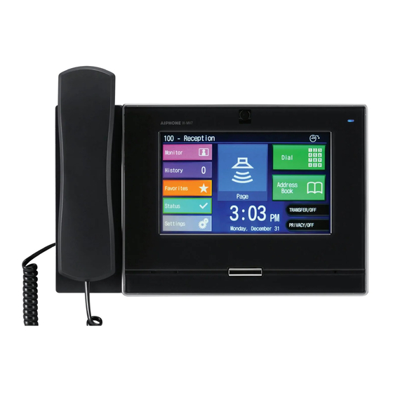
IX-MV7
ATTENTION:
This is an installation and programming manual addressing wiring and programming for the
IX-1AS / IX-10AS adaptor only. For general IX Series programming, refer to the IX Support Tool
Setting Manual or IX Quick Start Programming Guide.
Advertisement
Table of Contents

Related Manuals for Aiphone IX Series


Summary of Contents for Aiphone IX Series
- Page 1 IX-10AS IX-MV7 ATTENTION: This is an installation and programming manual addressing wiring and programming for the IX-1AS / IX-10AS adaptor only. For general IX Series programming, refer to the IX Support Tool Setting Manual or IX Quick Start Programming Guide.
- Page 2 The IX-1AS / IX-10AS adaptor is designed for use with Aiphone’s 2 wire LE and NE Series sub stations. This adaptor will allow these subs to be used with the IX Series network master station. First, connect the door station to the adaptor as shown in the table below, then connect the adaptor to the network.
-
Page 3: Step 3: Network Settings
Step 3: Network Settings Select Network Settings from the menu on the left. Enter a unique IP Address*, Subnet Mask, and Gateway IP Address for the adaptor. Consult with your IT department for the appropriate addresses to be assigned. There are additional settings on the Network Settings page that can be adjusted: SIP Settings, Audio Settings, and Packet Priority. -
Page 4: Step 5: Call Settings
Step 5: Call Settings Select Call Settings from the menu on the left. From this screen, enter the station number and IP address of the master(s) that this door station needs to call. A maximum of 20 master stations can be entered (example: 101@192.168.1.165). These station numbers and IP Addresses must match what is assigned to the IX-MV / IX-MV7 master(s) in IX Support Tool. - Page 5 Step 6: Function Settings (continued) SIF Reporting and SIF Events can be enabled from the same Function Settings screen. This is used when integrating with access control platforms (i.e. RY-IP44). Enter the IP address (of 3rd party device), Port (of 3rd party device), and Program number for each destination under SIF Reporting.
-
Page 6: Step 8: Maintenance (Optional)
Step 8: Maintenance (optional) Select Maintenance from the menu on the left. If a Syslog server is being used on the network, the IP address for the server can be entered here. If Syslog Address is left to the 0.0.0.0 address, the log will be broadcast. Enable debug mode for additional syslog messages to aid in troubleshooting. -
Page 7: Step 10: Assigning Ip Address
Step 10: Assigning IP Address Now that the station has been added, the IP address will need to be assigned. From the menu on the left, select IP Address from the Network Settings tree. The newly added station will be in the list of stations. Enter the IP address and subnet mask, making sure it matches what was set to the IX-1AS during its initial programming (Step 3). -
Page 8: Specifications
Step 12: Uploading Settings The IX Series master stations will now need to be updated with the saved changes. Select Upload Settings To Station from the File menu. Select the master stations from the list and click Settings. The settings will upload to the master stations and the Status column will show if the upload was successful.