Advertisement
Quick Links
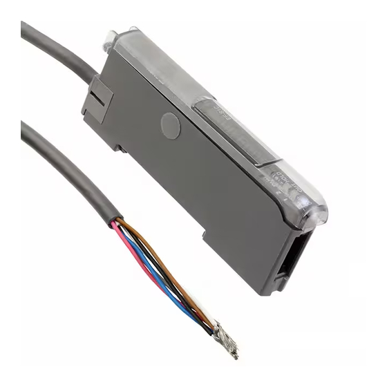
Electrostatic Sensor Controller
EF-S1C
Thank you very much for using Panasonic products. Please read this Instruction
Manual carefully and thoroughly for the correct and optimum use of this product.
Kindly keep this manual in a convenient place for quick reference.
Never use this product with a device for personnel protection.
In case of using devices for personnel protection, use products
which meet laws or standards, such as OSHA, ANSI or IEC etc., for
WARNING
personnel protection applicable in each region or country.
1
OUTLINE
This product can be used in combination with a exclusive sensor head (EF-S1HS)
(optional) to monitor electrical potentials on object surfaces.
It can also be used together with an ionizer to check results of charge removal
processes.
2
PART DESCRIPTION
Select 2 indicator (Y ellow)
Select 1 indicator (Yellow)
Output 2 operation indicator (Orange)
Output 1 operation indicator (Orange)
Timing indicator
(Green)
MODE indicator / RUN (Green)
MODE indicator /
MODE indicator / DIST (Y ellow)
HOLD (Y ellow)
3
MOUNTING
How to mount the controller
Fit the rear part of the mounting section of the controller
on a 35mm width DIN rail.
Press down the rear part of the mounting section of
the unit on the 35mm width DIN rail and fit the front
part of the mounting section to the DIN rail.
How to remove the controller
Push the controller forward.
Lift up the front part of the controller to remove it.
Note:
T ake care that if the front part is lifted without pushing the
controller forward, the hook on the rear portion of the
mounting section is likely to break.
How to mount the sensor head
Insert the sensor head connector into the inlet until it
clicks.
Fit the cover to the connector.
4
I/O CIRCUIT DIAGRAM
Color code
(Brown) + V
(Black) Output 1
(White) Output 2
(Grey) Analog output
100
5V
(Pink)Timing input / 0-Adjust input
(Blue) 0V
Internal circuit
Users' circuit
Note:
If using together with an ionizer manufactured by Panasonic, share the 0V line of this product
with the ground of the ionizer, and carry out 0-Adjust when doing 0V measurements.
*1
<Points to note when using analog output>
Non-voltage contact or
Because the 0V lines for judgment output and
NPN transistor open collector
analog output are common, the analog output may
or
vary depending on the load current.
In order to satisfy the linearity specifications for the
High (+V , or open): Invalid
analog output, do not use the judgment output.
Low (0 to +2V):Valid
Ramco National
INSTRUCTION MANUAL
CME-EFS1C No.0032-47V
MODE indicator / TIMER (Y ellow)
MODE indicator / CUSTOM (Y ellow)
MODE key
1
MODE indicator /
PRO (Y ellow)
Jog switch
2 3
Digital display (Green, Red)
35mm width DIN rail
Sensor head
connector
Cover
Load
Load
100mA max.
+
100mA max.
24V DC
-
10%
*1
800-280-6933 | nsales@ramcoi.com
5
OPERATION PROCEDURE AND BASIC SYSTEM
MODE key
1
Press
'+' side
Switching NAVI mode
Moving setting menu
Canceling while
Changing setting values
setting is in progress
Display value hold
0-Adjust
Basic system of operation for NAVI mode
(For details, refer to '
Run
RUN
DIST
This indicates normal sensing
This sets the measurement dis-
operation. The threshold value
tance and measurement range.
can be adjusted and 0-Adjust
can be carried out as well.
PRO
Pro
CUST
Allows various detailed set-
This displays items that have
tings to be configured, such as
been set using PRO5 mode and
load / save and other settings.
CUST mode display functions.
Basic system of operation for PRO mode
Notes: 1)
Judgment output and analog output will become unstable while setting operations are
being carried out. After settings have been completed, use in RUN mode.
2)
If the power is turned off while settings are being confirmed (while the display is blinking),
the settings may not be applied correctly.
6
RUN MODE
In this mode, the current measurement value and threshold value are displayed,
and the threshold value can be set and 0-Adjust, key lock and display
(Note 1)
value hold and charge removal time measurement operations can be carried out.
Notes: 1)
At the time of shipment, the threshold value is set to be displayed in the green (left) digital
display. When the symbol display setting is ON (refer to PRO2 mode), a symbol ("-" only)
appears in the green (left) digital display.
Threshould
Measurement
Threshold value setting
(Note 1)
value
value
+ threshold value setting screen
Press
- threshold value setting screen
Press
Notes: 2)
0-Adjust setting (cancel)
Press for
This sets the measurement value to zero (baseline).
1 sec. or
more
When the MODE key is pressed once more for 1
sec. or more, 0-Adjust can be canceled.
Notes: 3)
4)
Press for
2 sec. or
Key lock
+
more
If the MODE key and the jog switch are pressed
together for 2 sec. or more, the key lock is canceled.
Press to
Display value hold
+ side for
1 sec. or more
If the jog switch is turned to the '-' side for 1 sec. or
more, the hold is canceled.
Notes: 5)
6)
Charge removal time measurement
Notes: 7)
This is enabled when
This measures 'Charge removal time(sec.)' from
TIMER mode is set to
1000 to 100 automatically and display it.
'Charge removal time
measurement'.
A start and a stop of the measurement are possible
with the jog switch.
Jog switch
2
T urn
3
Press
'-' side
Confirming menu
settings
Confirming setting
values
NAVI
MODE'.)
7
Distance / Range
Hold
HOLD
This sets HOLD mode.
Custom
TIMER
Timer
Configures operation and period
of the timer, or charge removal
time measurement function.
(For details, refer to '
PRO
MODE'.)
9
T urn
Press
Press:
Confirmed
T urn
For details on the setting range for the threshold
value, refer to '
8
SETTING RANGE'.
Automatically
Automatically
If the measurement value exceeds
200, 0-Adjust
cannot be carried out.
When 0-Adjust setting input has been selected as
the external input setting, 0-Adjust can be carried
out each time using the external input signal.
Automatically
Automatically
This is enabled when HOLD mode is set to OFF.
Refer to '
4
EXTERNAL INPUT OPERATIONS
AND HOLD MEASUREMENT' in the instruction
manual included (if using the EF-S1 series surface
potential sensor for the first time) for details on the
operation when HOLD mode is set to ON.
Only the display value is held. Output is not held.
Ex.)
Charge removal time is 1.2 sec.
www.panasonicsensors.com
7
NA
If the M
R UN m
DIST m
HOLD
TIMER
CUST
PR O m
Press
Notes:
1)
F
2)
T
d
t
3)
If
s
4)
W
w
8
SE
The th
Dista
( 1
Dista
( 2
0-adju
-200
Calibr
0.5
Dista
Dista
Advertisement

Related Manuals for Panasonic EF-S1C


Summary of Contents for Panasonic EF-S1C
- Page 1 If the jog switch is turned to the '-' side for 1 sec. or Note: If using together with an ionizer manufactured by Panasonic, share the 0V line of this product more, the hold is canceled. with the ground of the ionizer, and carry out 0-Adjust when doing 0V measurements.
- Page 2 STEM NAVI MODE PRO MODE If the MODE key is pressed, the mode can be changed to a different mode. If 'PR O' is selected in NAVI mode, the mode changes to PR O mode. Basic system of operation for PRO mode R UN mode Refer to ' R UN...