
Related Manuals for Pentair Fairbanks Nijhuis 1590-SC Series


Summary of Contents for Pentair Fairbanks Nijhuis 1590-SC Series
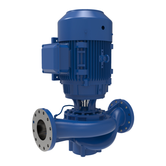
- Page 1 VERTICAL IN-LINE SPLIT COUPLED PUMPS 1590-SC SERIES Single Suction Pump Double Suction Pump INSTALLATION AND OPERATION MANUAL pentair.com FM-03-534 (11/18/19)
-
Page 2: Table Of Contents
TABLE OF CONTENTS: SECTION .........................................PAGE General Information ....................................3 Transport and Storage .................................... 4 Product Description ....................................5 Pump Installation ....................................6-7 Pump Operation ...................................... 8 Pump Maintenance and Service .................................9-16 Troubleshooting Guide ..................................17-18 Assembly Exploded View .................................. 19-21 Part List ........................................ -
Page 3: General Information
Always follow lock out – tag out procedures when working the system. on equipment that may turn on. This manual contains important information for the safe use of Pentair Drain the pump and isolate pipe work before dismantling Fairbanks Nijhuis® 1590 Vertical In-line Split Coupled Pumps. Read this the pump. -
Page 4: Transport And Storage
TRANSPORT AND STORAGE While lifting the pump or pump set (with or without driver) suitable lifting equipment of adequate capacity should be used. The unit should be • Ensure correct lubrication. See “Lubrication” on Page 8 for unloaded and handled by lifting equally. Entire pump should be lifted at lubrication instruction. -
Page 5: Product Description
PRODUCT DESCRIPTION This should be done at once. Do not unpack any more than required Long-Term Storage to verify that the equipment is complete and undamaged unless All pumps are factory serviced and delivered in a ready to operate installation is to be done immediately. Do not leave the pump unit or any condition. -
Page 6: Pump Installation
OUTLET specified. 1. Hanger Supported Pipe Mounted Where floor space is a restriction, Pentair Fairbanks Nijhuis® 1590-SC Vertical In-line pumps can be installed in the system piping without any SUPPORT STRUCTURE additional support from base, as illustrated in Figure 2 shown below. For... - Page 7 For sumps below center line the straight side of the reducer must be located upwards so Pipe flange sizes for Pentair Fairbanks Nijhuis® 1590-SC pumps that any air cavity if present in the suction line passes through the line to...
-
Page 8: Pump Operation
PUMP OPERATION elastomeric or metallic flexible member. Mechanical seals are made in a PUMP OPERATION wide variety of designs; therefore the instructions for the specific seal must be carefully studied and followed. A mechanical seal is a precision COMMISSIONING device and must be treated accordingly. Mechanical seals normally require no adjustment during operation. -
Page 9: Pump Maintenance And Service
During this operation the mechanical seal would ‘seat’ check the separator. A suggested guide for preventive maintenance for properly. normal application is given below in Table 2. Pentair Fairbanks Nijhuis® 1590-SC pumps are supplied with three basic Table 2 types of seals: GUIDE FOR PREVENTIVE MAINTENANCE 1. - Page 10 PUMP MAINTENANCE AND SERVICE Consumables FOR PUMPS Following items are of regular use during preventive & accidental (14" 1591, 14" 1593) maintenance and must be kept in stock by the customer: Wrench Size & Type • Lubricants Hardware Location (in inches) •...
- Page 11 PUMP MAINTENANCE AND SERVICE FOR ALL OTHER PUMPS Mechanical Seal Replacement Refer to tools mentioned in the tables under "Required Tools and Refer to "Assembly Exploded View" Figure 35 on Page 21 for item Fixtures" on Pages 10 - 11. numbers.
- Page 12 PUMP MAINTENANCE AND SERVICE 3. Remove the coupling guards (#17) by removing the four (per side) cap contact with the bottom of the retaining ring (#41A). Make sure to screws (#18). Loosen the ferrule nuts on the tubing connectors (#1) alternate tightening of the bolts so the gland is raised evenly.
- Page 13 PUMP MAINTENANCE AND SERVICE 22. Using one half of the split coupling as a guide, (the tapping for set screws identifies the motor side of the coupling) utilize the jacking bolts to raise the shaft (with impeller) upward until the step inside the coupling touches motor shaft end face so that pre-specified GLAND distance between pump shaft and motor shaft is maintained.
- Page 14 PUMP MAINTENANCE AND SERVICE FOR TYPE 8B2 MECHANICAL SEAL 28. Loosen the four gland bolts (#55). Keeping the two bolts engaged GLAND REMOVED with the gland to restrict the motion of the gland about shaft axis, THROUGH GAP BETWEEN SHAFTS engage the other two bolts into the threaded holes in jacking plate (#10) (supplied separately with pump).
- Page 15 PUMP MAINTENANCE AND SERVICE that pre-specified distance between pump shaft and motor shaft is Complete Pump Disassembly maintained. FOR PUMPS (10" 1592, 10" 1594, 12" 1591, 12" 1593, 14" 1591 and 14" 1593 only) MOTOR SHAFT 1. With the coupling (#45), gland (#44) and mechanical seal (#27) removed, remove the bolts (#32), nuts (#31) and washers (#32A) holding the motor to the bracket.
- Page 16 PUMP MAINTENANCE AND SERVICE 8. Unscrew impeller screw (#9), remove impeller washer (#9A) and impeller seal (#9C). 9. Slide impeller (#11) and impeller key (#12) from shaft. 10. Remove spire bush (#13) from the impeller bore using a small puller. During reassembly the new bushing must be pressed evenly or it can crack.
-
Page 17: Troubleshooting Guide
TROUBLESHOOTING GUIDE THE FOLLOWING IS A LIST OF COMMON PROBLEMS AND THEIR PROBABLE CAUSES. Symptoms Possible causes Possible remedies Check and ensure correct voltage at motor terminals Speed too low Check if rotating elements freely rotate Check motor rotation with direction arrow on casing Wrong direction of rotation Ensure correct motor wiring Ensure all air is vented, and pump is adequately primed... - Page 18 Rubbing or binding of rotating elements stationary components Note: The pump delivered may not be fitted with all the components mentioned in the troubleshooting guide. For further troubleshooting assistance, contact Pentair Fairbanks Nijhuis Customer Service or your nearest Pentair Fairbanks Nijhuis authorized distributor. FM-03-534 (11/18/19)
-
Page 19: Assembly Exploded View
ASSEMBLY EXPLODED VIEWS PENTAIR FAIRBANKS NIJHUIS® MODEL 1590-SC TC-Motor (Model 10" 1594) 8B2 SEAL COMPONENTS OMITTED WHEN 8B2 SEAL IS USED Figure 33 Figure 33 FM-03-534 (11/18/19) - Page 20 ASSEMBLY EXPLODED VIEWS PENTAIR FAIRBANKS NIJHUIS® MODEL 1590-SC TC-Motor (Models 10" 1592, 12" 1591, 12" 1593, 14" 1591 and 14" 1593) 8B2 SEAL COMPONENTS OMITTED WHEN 8B2 SEAL IS USED 10" 1592 COMPONENTS Figure 34 Figure 34 FM-03-534 (11/18/19)
- Page 21 ASSEMBLY EXPLODED VIEWS PENTAIR FAIRBANKS NIJHUIS® MODEL 1590-SC TC-Motor ALL OTHER PUMP MODELS OMITTED WHEN 8B2 SEAL IS USED 8B2 SEAL COMPONENTS Figure 35 FM-03-534 (11/18/19)
-
Page 22: Part List
PART LIST PART LIST FOR PENTAIR FAIRBANKS NIJHUIS® 1590-SC VERTICAL IN-LINE PUMPS Reference “Exploded Views” Figures 33, 34 and 35 on Pages 19-21 ITEM NO. DESCRIPTION COMPRESSION ELBOW COMPRESSION CONNECTOR TUBING PIPE PLUG PIPE PLUG CAP SCREW WASHER CASING WEAR RING... -
Page 23: Pump - Impeller Size Relation
PUMP - IMPELLER SIZE RELATION PUMP MODEL MAX IMPELLER DIAMETER 1-1/2" 1591 2" 1592A 2-1/2" 1591A 3" 1594A 7" 4" 1595A 5" 1591A 6" 1591A 1-1/2" 1592 2-1/2" 1592 3" 1595 4" 1596 9.5" 5" 1592 6" 1592A 8" 1591A 2"... -
Page 24: Standard Limited Warranty
STANDARD LIMITED WARRANTY WARRANTY Seller warrants equipment (and its component parts) of its own manufacture against defects in materials and workmanship under normal use and service for one (1) year from the date of installation or start-up, or for eighteen (18) months after the date of shipment, whichever occurs first. Seller does not warrant accessories or components that are not manufactured by Seller;... - Page 25 *For a detailed list of where Pentair trademarks are registered, please visit www.pentair.com/en/registrations.html. Pentair trademarks and logos are owned by Pentair PLC. or its affiliates. Third party registered and unregistered trademarks and logos are the property of their respective owners. Because we are continuously improving our products and services, Pentair reserves the right to change specifications without prior notice.