Table of Contents
Advertisement
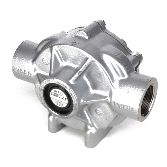
Hypro Series 1502, 1700, 4001, 4101,
6500, 7560 and 7700 Roller Pumps
L-0100R
® ®
Rev. C
HYPRO
Original Instruction Manual
Keep for Future Reference
Series 1502
Series 1700
6-Roller Pump
5-Roller Pump
Series 4001 & 4101
Series 6500
4-Roller Pump
6-Roller Pump
Series 7560
Series 7700
8-Roller Pump
7-Roller Pump
Pentair
Advertisement
Table of Contents

Related Manuals for Pentair Hypro Series


Summary of Contents for Pentair Hypro Series
- Page 1 Hypro Series 1502, 1700, 4001, 4101, 6500, 7560 and 7700 Roller Pumps L-0100R ® ® Rev. C HYPRO Original Instruction Manual Keep for Future Reference Series 1502 Series 1700 6-Roller Pump 5-Roller Pump Series 4001 & 4101 Series 6500 4-Roller Pump...
- Page 2 Contents - 2 -...
- Page 3 EU Language Manuals - 3 -...
-
Page 4: Intended Uses
Introduction Description Intended Use(s) Purpose of Manual California Proposition 65 Warning - 4 -... -
Page 5: Pump Identification
Introduction - cont’d. Misuses Pump Identification Serial Number: First and second digits Third through fifth digits - 5 -... -
Page 6: Pump Technical Data
Pump Technical Data 1502 Series Pump Only Performance Data 1502C, 1502N, 1502XL (Imperial) Performance Data 1502C, 1502N, 1502XL (Metric) Pressure Pressure @540 RPM @600RPM @1000RPM @540 RPM @600RPM @1000RPM 0 PSI 33.1 36.8 62.1 0 BAR 125.3 139.3 235.1 25 PSI 29.7 33.6 58.5... - Page 7 Pump Technical Data 1700 Series Pump Only - 7 -...
- Page 8 Pump Technical Data 4001 Series Pump Only Pump Dimensions Dim. Inch 4.75 2.38 1.67 3.03 5.39 3.34 1.00 0.49 1.43 2.96 1.75 Performance Data 4001C, 4001N, 4001X (Imperial) Performance Data 4001C, 4001N, 4001XL (Metric) Pressure Pressure @1100 RPM @1400RPM @1800RPM @1100 RPM @1400RPM @1800RPM...
- Page 9 Pump Technical Data Motorized Pump Dimensions Dim. Inch 5.12 2.56 2.54 5.17 (5.15) 131 (130) 13.24 (11.91) 336 (302) 4.45 8.79 (7.45) 223 (189) 2.63 Model 4001N-EH & 4001XL-EH (Imperial) Model 4001N-EH & 4001XL-EH (Metric) Volts AMPS Volts AMPS Volts AMPS Volts AMPS...
- Page 10 Pump Technical Data 4101 Series Pump Only Pump Dimensions Dim. Inch 4.75 2.38 1.67 3.03 5.39 3.34 1.00 0.49 1.43 2.96 1.75 Performance Data 4101C, 4101N, 4101XL (Imperial) Performance Data 4101C, 4101N, 4101XL (Metric) Pressure Pressure @1800 RPM @2200RPM @2600RPM @1800 RPM @2200RPM @2600RPM...
- Page 11 Pump Technical Data Motorized Pump Dimensions Dim. Inch 5.12 2.56 2.54 5.17 (5.15) 131 (130) 13.24 (11.91) 336 (302) 4.45 8.79 (7.45) 223 (189) 2.63 - 11 -...
-
Page 12: Gas Engine
Pump Technical Data Gas Engine 4101C-25, 4101XL-25 Pump Specifications Max. Flow Continuous Intermittent Max. Pressure Dry Weight Mounting Rollers: Rate Max RPM Ports: Shaft: Operation Operation Engine (PSI [BAR]): (LBS [KG]) Bolts (GPM [LPM]): (PSI [BAR]): (PSI [BAR]): ” NPT Inlet 5/8”... - Page 13 Pump Technical Data 6500 Series Pump Only Performance Data 6500C, 6500N, 6500XL (Imperial) Performance Data 6500C, 6500N, 6500XL (Metric) Pressure Pressure @540 RPM @1000RPM @1200RPM @540 RPM @1000RPM @1200RPM 0 PSI 18.2 21.8 0 BAR 36.7 68.9 82.5 50 PSI 16.5 20.1 3.4 BAR...
- Page 14 Pump Technical Data 7560 Series Pump Only - 14 -...
- Page 15 Pump Technical Data Hydraulic 7560C-GM30, 7560N-GM30, 7560XL-GM30 Pump Specifications Max. Pump Max. Pump Continuous Intermittent Max . Max. Hydraulic Hydraulic Dry Weight Mounting Rollers: Flow Rate Pressure Max RPM Ports: Operation (PSI Operation (PSI Hydraulic Flow Pressure Motor Ports (LBS [KG]) Bolts (GPM [LPM]): (PSI [BAR]):...
- Page 16 Pump Technical Data Hydraulic - cont’d. 7560C-GM15, 7560N-GM15, 7560XL-GM15 Pump Specifications Max. Pump Max. Pump Continuous Intermittent Max. Max. Hydraulic Hydraulic Dry Weight Mounting Rollers: Flow Rate Pressure Max RPM Ports: Operation (PSI Operation (PSI Hydraulic Flow Pressure Motor Ports (LBS [KG]) Bolts (GPM [LPM]):...
- Page 17 Pump Technical Data 7700 Series Pump Only Performance Data 7700C, 7700N, 7700XL (Imperial) Performance Data 7700C, 7700N, 7700XL (Metric) Pressure Pressure @540 RPM @600RPM @800RPM @540 RPM @600RPM @800RPM 0 PSI 14.2 15.3 22.1 0 BAR 53.8 57.9 83.7 50 PSI 12.9 14.0 20.7...
-
Page 18: Fluid Pumping Applications
Fluid Pumping Applications Pump Materials Compatibility Application Comments Cast Iron Ni-Resist Silver Series XL Only Ni- Resist and Silver series pumps should be used with Roundup. Table 1 Tools Lifting, Transport and Intermediate Storage Packaging Descriptions and Unpacking Instructions Lifting Instructions - 18 -... -
Page 19: Installation
Lifting, Transport and Intermediate Storage - cont’d. Figure 1 Transport Storage Assembly and Installation Assembly Installation - 19 -... - Page 20 Assembly and Installation - cont’d. Standard Mounting Tractor PTO Installation Figure 2 - 20 -...
- Page 21 Assembly and Installation - cont’d. Belt/Pulley Drive Installation Example: Figure 4 Figure 3 d = 0.016 x L Figure 5 Direct Drive-Flexible Coupling ATTENTION: - 21 -...
- Page 22 Assembly and Installation - cont’d. Figure 6 System Installation ATTENTION “IN” “OUT” Attention: Suction lift not to exceed 3 feet. Bypass Line Pump Pressure Regulator Figure 7 Typical System Installation Strainer Pressure Relief Valve ELECTRICAL HOOK-UP FOR UNITS SUPPLIED WITH DC MOTOR - 22 -...
-
Page 23: Control Systems
Assembly and Installation - cont’d. ON/OFF TOGGLE SWITCH INSTALLATION ON/OFF Toggle Switch Slow-blow Fuse or circuit breaker 12-volt Battery Figure 8 Hooking up the Hydraulic Motor to the Tractor Hydraulic System Keep all hydraulic connections clean. Control System(s) Commissioning Start-Up, Operation, Shutdown Information - 23 -... -
Page 24: Start-Up, Operation, Shutdown
Commissioning Start-Up, Operation, Shutdown - cont’d. Only use approved chemicals in your pump. For a complete list of approved chemicals, see the “Fluid Pumping Applications” section. Failure to follow this warning will void your warranty and could lead to property damage, serious injury or death. Start-Up, Operation, Shutdown Before Starting the Pump Priming the Pump... - Page 25 Start-Up, Operation, Shutdown - cont’d. Pumps Equipped with Hydraulic Motor Startup and Operation Open Center Systems Closed Center (Load Sensing) Systems Shutdown PTO/Belt Drive/Flexible Coupling Startup and Operation DO NOT Shutdown - 25 -...
-
Page 26: Replacement Parts
Maintenance and Servicing Information Disposal Cleaning Maintenance, Routine Servicing, and Inspection Preventative Maintenance Checklist Check Daily Weekly Replacement Parts Only genuine replacement parts should be used. Failure to follow this warning can result in damage to property, serious injury or death. - 26 -... -
Page 27: Parts Illustration
Parts Illustration Series 1502 IMPORTANT: Ref. Qty. Part Ref. Qty. Part No. Req'd. Number Description No. Req'd. Number Description Sold Separately Repair Parts Kit No. 3430-0383 (Universal) Repair Parts Kit No. 3430-0164 Repair Parts Kit No. 3430-0163 Repair Parts Kit No. 3430-0386 Repair Parts Kit No. - Page 28 Parts Illustration Series 1700 IMPORTANT: Ref. Qty. Part Ref. Qty. Part No. Req'd. Number Description No. Req'd. Number Description Sold Separately Repair Parts Kit No. 3430-0437 Repair Parts Kit No. 3430-0161 Repair Parts Kit No. 3430-0383 (Universal) Repair Parts Kit No. 3430-0407 Repair Parts Kit No.
- Page 29 Parts Illustration Series 4001 and 4101 15 16 IMPORTANT: Ref. Qty. Part Ref. Qty. Part No. Req'd. Number Description No. Req'd. Number Description Sold Separately Sold Separately Sold Separately Sold Separately Sold Separately Sold Separately Sold Separately Sold Separately Repair Parts Kit No. 3430-0390 Repair Parts Kit No.
- Page 30 Parts Illustration Models 4101C-25 and 4101XL-25 Ref. Qty. Part IMPORTANT: No. Req'd. Number Description Repair Parts Kit No. 3430-0390 - 30 -...
- Page 31 Parts Illustration Series 4001 and 4101 Electric Motor-Driven Pumps When ordering parts, give QUANTITY, PART NUMBER, DESCRIPTION COMPLETE MODEL NUMBER. Reference numbers are used ONLY to identify parts in the drawing and are NOT to be used as order numbers. Ref.
- Page 32 Parts Illustration Series 6500 Repair Parts Kits: No. 3430-0380 IMPORTANT: No. 3430-0175 Ref. Qty. Part Ref. Qty. Part No. Req'd. Number Description No. Req'd. Number Description Sold Separately - 32 -...
- Page 33 Parts Illustration Series 7560 Repair Parts Kits: No. 3430-0381 IMPORTANT: No. 3430-0167 Ref. Qty. Part Ref. Qty. Part No. Req'd. Number Description No. Req'd. Number Description Sold Separately - 33 -...
- Page 34 Parts Illustration Models 7560C-GM30, 7560N-GM30, and 7560XL-GM30 Models 7560C-GM15, 7560N-GM15, and 7560XL-GM15 Ref. Qty. Part Ref. Qty. Part No. Req'd. Number Description No. Req'd. Number Description Repair Parts Kit No. 3430-0381 Repair Parts Kit No. 3430-0167 Flange Kit No. 3430-0636 - 34 -...
- Page 35 Parts Illustration Series 7700 Repair Parts Kits: No. 3430-0384 IMPORTANT: No. 3430-0167 Ref. Qty. Part Ref. Qty. Part No. Req'd. Number Description No. Req'd. Number Description Rev. Rot. Rev. Rot. Rev.Rot. Sold Separately - 35 -...
-
Page 36: Troubleshooting Guide
Troubleshooting Troubleshooting Guide Symptom Probable Cause(s) Corrective Action Table 2 - 36 -... -
Page 37: Repair Instructions
Repair Instructions To Take the Pump Apart Figure 9 Figure 10 While the Pump is Apart ATTENTION: If an attempt has been made to pry the pump apart with a screwdriver, be sure to file off all nicks, burrs and other damage marks around the bolt holes. - Page 38 Repair Instructions - cont’d. Assemble Rotor and Shaft to Endplate Figure 12 ATTENTION: Before new parts are installed, all burrs should be removed, particularly in the rotor slots and body. Do not machine clean the body casting. A more satisfactory job can be done by hand cleaning with an emery cloth. ATTENTION Figure 13 Center Rotor in Pump Case...
- Page 39 EC Declaration of Incorporation Manufacturers Name: Pentair Flow Technologies, LLC Manufacturers’ Address: Declare that the partially complete machinery described below conforms to applicable health and safety requirements of Parts 1 of Annex I of Machinery Directive 2006/42/EC. This partly completed machinery must not be put into service until the equipment into which it is to be incorporated has been declared in conformity with the provisions of this directive.
-
Page 40: Return Procedures
Limited Warranty on Hypro/SHURflo Agricultural Pumps & Accessories Return Procedures Contact Hypro Service Department at 800-468-3428 to receive a Return Merchandise Authorization number (RMA#). shipping charges prepaid Hypro Technical/Application number: 800-445-8360 technical@hypropumps.com Hypro Service and Warranty number 800-468-3428 Hypro Service and Warranty FAX 651-766-6618 Visit www.hypropumps.com/register today to register your product and stay up-to-date on new products and promotional offers.