Table of Contents
Advertisement
Advertisement
Table of Contents

Related Manuals for Apex Digital Digi Combo


Summary of Contents for Apex Digital Digi Combo
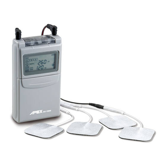
- Page 1 Model: GM320TE (COMBO)
- Page 2 SYMBOLS Manufacturer. Authorised representative in the European Community. CE mark and notified body registration number, the Annex II article 3 of EC directive 93/42/EEC have been met. “BF” symbol, indicate this product is according to the degree of protecting against electric shock for type BF equipment. Consult operating instructions for use.
-
Page 3: Table Of Contents
CONTENTS GENERAL DESCRIPTION . . . . . . . . . . . . . . . . . . . . . . . . . . . . . . . . . . . . . . . . . . . . . . . . . . . . . . . . . . . . . . . . . . . 1 SYSTEM COMPONENTS . -
Page 4: General Description
GENERAL DESCRIPTION Electric myostimulation has proven its high value as a method of pain therapy and is a great help to the experienced therapist. With some indications, physicians can prescribe unit to patients for the use at home. The unit is a dual-Channel electric stimulator for active treatment application, which is equipped with a Liquid Crystal Display indicating operation modes and output as well as an 8-bit micro computer for controlling the system. -
Page 5: Warranty
WARRANTY This device carries a one-year warranty from the date of purchase. The warranty applies to the de- vice and necessary parts and labor relating thereto. The distributor reserves the right to replace or repair the unit at their discretion. The warranty does not apply to electrode, battery, lead wires, carrying case, damage resulting from failure to follow the operating instructions, accidents, abuse, alterations or disassembly by unauthor- ized individuals. - Page 6 The following statements are available for TENS operation function Indications for use This device is a prescription device and only for symptomatic relief of chronic intractable pain. Contraindications ● Any electrode placement that applies current to the carotid sinus (neck) region. ●...
- Page 7 The following statements are available for EMS operation function Indications for use ● Relaxation of muscle spasms. ● Prevention or retardation of disuse atrophy. ● Increasing local blood circulation. ● Muscle re-education. ● Immediate post-surgical stimulation of calf muscles to prevent venous thrombosis. ●...
-
Page 8: Warnings And Precautions
WARNINGS AND PRECAUTIONS The following statements are available for TENS operation function Warnings ● The device must be kept out of reach of children. ● The safety of device for use during pregnancy or delivery has not been established. ● Do not place electrodes on front of the throat. This may result is spasms of the laryngeal and pha- ryngeal muscles. - Page 9 Precautions/adverse Reactions ● Isolated cases of skin irritation may occur at the site of electrode placement following long-term application. ● Stimulation should be stopped and electrodes removed until the cause of the irritation can be de- termined. ● Effectiveness is highly dependent upon patient selection by a person qualified in the management of pain patients.
- Page 10 cause difficulty in breathing. ● Stimulation should not be applied transthoracically in that the introduction of electrical current into the heart may cause cardiac arrhythmias. ● Stimulation should not be applied over swollen, infected, or inflamed areas or skin eruptions, e.g. phlebitis, thrombophlebitis, varicose veins, etc.
-
Page 11: Danger
● Electrode placement and stimulation settings should be based on the guidance of the prescribing practitioner. ● Powered muscle stimulators should be kept out of the reach of children. ● Power muscle stimulators should be used only with the leads and electrodes recommended for use by the manufacturer. -
Page 12: About The Device
ABOUT THE DEVICE Your device offers two controllable output channels. This device creates electrical impulses whose amplitude, duration, and modulation can be altered with the controls or buttons. The device controls are very easy to use, the cap and slide cover protect accidental changes in settings. -
Page 13: The Device Controls
THE DEVICE CONTROLS Panel cover ▲▼ A cover conceals the controls for Mode, Time, Width (SET/ENT), Rate▲▼ (▲▼). Press the topside of the cover and pull down in order to open the cover. Intensity The intensity knobs are located on the top of the unit under the cap for the strength adjustment of the stimulation and also function as ON/OFF controls. - Page 14 60 min : 15, 30 and 60 min symbols light on. Continuous : 15 and 30 min symbols light on, and the 60 min symbol flashes. To reset timer, turn both channels off. When you are ready to begin another treatment cycle (at least rest for 7 seconds), turn the unit on as normal.
-
Page 15: Attaching The Lead Wires
ATTACHING THE LEAD WIRES The lead wires provided with the device insert into the jack sockets located on top of the unit. Holding the insulated portion of the connector, and pushing the plug end of the wire into one of the jacks. After connecting the wires to the stimulator, attach each wire to an electrode. -
Page 16: Tips For Skin Care
TIPS FOR SKIN CARE Good skin care is important for comfortable use of your device. ● Always clean the electrode site with mild soap and water solution, rinse well, and blot dry thoroughly prior to any electrode application. ● Any excess hair should be clipped, not shaved, to ensure good electrode contact with the skin. ●... -
Page 17: Connecting The Device
CONNECTING THE DEVICE 1. Prepare the Skin Prepare the skin as previously discussed and according to instructions provided with your electrodes. Before attaching the electrodes, identify the area in which your physician/practitioner has recommend- ed for electrode placement. 2. Connect lead wires to the electrodes Connect the lead wires to the electrodes before applying the electrodes to the skin. -
Page 18: Battery Information
6. Adjusting Channel Intensity Control Locate the intensity control knobs at the top of the unit under the cap. Open the cap first, slowly turn the intensity control knob for Channel 1 clockwise until you reach the intensity recommended by your medical professional. -
Page 19: Changing The Battery
CHANGING THE BATTERY When the low-battery indicator appears on the LCD panel, the battery should be replaced with a fresh battery. 1 . Remove the slide cover by pressing the top and sliding down until it is completely removed from the unit . -
Page 20: Troubleshooting
TROUBLESHOOTING If the device does not function properly: 1 . Make sure the battery is properly installed, or replace the battery . Be sure to observe proper polarity markings when replacing the battery . If the low-battery indicator appears when the unit is turned on, replace the battery and check again . -
Page 21: Technical Specifications
TECHNICAL SPECIFICATIONS Channel Dual, isolated between channels Pulse amplitude Adjustable 0-80mA peak into 500 Ω load each channel, constant current Pulse Rate 1Hz-160Hz (adjustable), 1Hz/step (1-20Hz), 5Hz/step (20-160Hz) Pulse Width a. 50-260μs adjustable for TENS, 10μs/step b. 250μs fixed for EMS Software ramp up By changing mode, the output will reset to zero then ramp up to its original setting feature... - Page 22 Function Modes: TENS Cycle Bursts, 2Bursts/sec, 9pulses/Burst, 100Hz, width is adjustable. Continuous mode. Pulse rate, pulse width and intensity are full adjustable. Modulated Width. Pulse width is automatically varied in an interval of 6 seconds. The modula- tion range of pulse width is from setting value to 35% less than the control setting value. And then returns to the setting value.
- Page 23 Synchronous Constant Alternation On Ramp Adjustable 1-8 seconds Cycle ON Time Adjustable 1-30 seconds Cycle OFF Time Adjustable 1-30 seconds Wave form Asymmetrical Bi-phasic square pulse Max charge per pulse 21 micro-coulombs maximum Voltage 0-110 Volt (Open Circuit) Power Source 9-Volt Battery Dimensions 108mm(H) ×61.5mm(W) ×25mm(T)
- Page 24 EMC INFORMATION Recommended separation distances between portable and mobile RF communications equipment and the ME equip- ment The ME equipment is intended for use in an electromagnetic in which radiated RF disturbances are controlled. The cus- tomer or the user of the ME equipment can help prevent electromagnetic interence by maintaining a minimum distance between portable and mobile RF communications equipment (transmitters) and the ME equipment as recommended below, according to the maximum output power of the communications equipment.
- Page 25 Declaration – electromagnetic emissions and immunity – for EQUIPMENT and SYSTEMS that are not LIFE-SUPPORTING The ME declaration – electromagnetic immunity The ME system is intended for use in the electromagnetic environment specified below. The customer or the user of the ME system should assure that it is used in such an environment. Immunity test IEC 60601 test level Compliance level...
- Page 26 Immunity test IEC 60601 test level Compliance level Electromagnetic environment - guidance ±2 kV for power supply ±2 kV for power Electrical fast tran- lines supply lines Mains power quality should be that of a typical commercial or sient/burst hospital environment. ±1 kV for input/output ±1 kV for input/out- 61000-4-4...
- Page 27 Power frequency Power frequency magnetic fields should be at levels charac- (50/60 Hz) mag- 3 A/m 3 A/m teristic of a typical location in a typical commercial or hospital netic field environment. IEC 61000-4-8 Declaration – electromagnetic emissions The ME system is intended for use in the electromagnetic environment specified below. The customer or the user of ME should assure that it is used in such an environment.
- Page 28 Appendix Manual for Doctor mode (for physician or licensed practitioner use only) It is possible for a physician or licensed practitioner to see the compliance meter, to reset the compli- ance meter or to lock/unlock the treatment parameters. This is achieved using doctor mode. 1 .
- Page 29 4 . Lock the parameter: After the doctor finish setting the prescription parameters, the doctor can lock the parameters to prevent a patient from altering the settings . When the doctor finish the prescription parameters, turn off the unit . Then enter the doctor mode ( refer to step 1) first .
- Page 32 APEX MEDICAL S.L. Elcano 9, 6 planta 48008 Bilbao. Vizcaya. Spain APEX MEDICAL CORP. No. 9, Min Sheng St., Tu-Cheng, New Taipei City, 23679, Taiwan www.apexbrand.com AP-320TE(COMBO)-A04 Print-2013/All rights reserved...