Advertisement
Quick Links
Advertisement

Related Manuals for Samsung MIM-F10N


Summary of Contents for Samsung MIM-F10N
- Page 1 DB68-06087A-00 @FCU AIM-F10N_IM_06087A-00_EN_160307.indd 2 2016-03-15 오후 5:11:53...
- Page 2 DVM CHILLER Installation manual FCU Interface Module MIM-F10N • Thank you for purchasing this Samsung Product. • Before operating this unit, please read this Insatallation manual carefully and retain it for future reference. @FCU AIM-F10N_IM_06087A-00_EN_160307.indd 3 2016-03-15 오후 5:11:53...
-
Page 3: Safety Precautions
Safety precautions This installation manual explains how to install a FCU interface module that is connected to a Samsung FCU KIT. Please read this manual thoroughly before installing the product. (Please refer to appropriate installation for any optional product installation.) WARNING Hazards or unsafe practices that may result in severe personal injury or death. - Page 4 Do not install the product in a place where flammable gas leaks or if there is possible chance of leakage. y There is risk of fire or explosion. Do not install the product in a place where it will be exposed to oil or vapor etc. y If the product is used in a place where it is exposed to oil, vapor or sulphur dioxide, parts of the product may get damaged or product may function abnormally.
- Page 5 INSTALLATION FCU interface module installation Accessories FCU interface DC power cable Communication Item Case Cable tie Screw (M4) module (12 V) cable Shape Diagram of connection between a FCU interface module and FCU KIT 1 Fix the FCU interface module case at fixing point of FCU KIT by 1 screw. 2 Attach FCU interface module to the case and connect power and communication cable.
- Page 6 Connecting FCU KIT y Connect DC power cable connector (Blue) to CN12 of FCU KIT MAIN PBA. y Communication cable (Red) is ring type. Connect the cable to F1, F2 terminal of FCU KIT MAIN PBA. FCU interface module Connect with upper level controller FCU KIT CAUTION •...
- Page 7 FCU interface module installation • You should be aware that power may not be supplied to FCU KIT and interface module if power polarity of V1 and V2 is connected opposite. • Terminal block of upper level controller connection on FCU interface module has to be tightened by M3 size screw, and the torque is 0.5 ~ 0.75 N.m.
- Page 8 About setting the main address manually and installation condition Manual address No function Automatic address y Automatic address: Address of the interface module is assigned randomly. y Manual address: Address of the interface module is assigned by address switch of the FCU interface module.
-
Page 9: Checking Operation
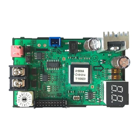
Checking operation LED Display 1 When resetting the power supply, the FCU interface module will not respond to the upper level communication for up to 10 minutes. When the communication with lower level (e.g.: between FCU interface module and FCU KIT) is detected as valid communication, Y-GRN LED will blink. - Page 10 5 When the FCU interface module tracking is not completed, will be indicated ↔ alternatively. y FCU KIT and FCU interface module may not be installed correctly. Check the installation, and reset the power of FCU interface module. 6 When there is an error on EEPROM of the FCU interface module, will be ↔...
- Page 11 Memo @FCU AIM-F10N_IM_06087A-00_EN_160307.indd 10 2016-03-15 오후 5:11:54...
- Page 12 @FCU AIM-F10N_IM_06087A-00_EN_160307.indd 11 2016-03-15 오후 5:11:54...