Table of Contents
Advertisement
Installation and Technical Manual for the
Limitless™ Series WDRR Receiver
WARNING
PERSONAL INJURY
• DO NOT USE these products as safety or emergency
stop devices or in any other application where failure of
the product could result in personal injury.
Failure to comply with these instructions could result in
death or serious injury.
WARNING
Honeywell does not recommend using devices for critical
control applications where there is, or may be, a single point
of failure or where single points of failure may result in an
unsafe condition. It is up to the end-user to weigh the risks
and benefits to determine if the products are appropriate for
the application based on security, safety and performance.
Additionally, it is up to the end-user to ensure that the
control strategy results in a safe operating condition if any
crucial segment of the control solution fails.
Honeywell customers assume full responsibility for learning
and meeting the required Declaration of Conformity,
Regulations, Guidelines, etc. for each country in their
distribution market.
Failure to comply with these instructions could result in
death or serious injury.
Sensing and Control
WARNING
RF EXPOSURE
• To satisfy FCC RF exposure requirements for mobile
transmitting devices, a separation distance of 20 cm or
more should be maintained between the antenna of this
device and persons during device operation To ensure
compliance, operation at closer than this distance is not
recommended. The antenna used for this transmission
must not be co-located in conjunction with any other
antenna or transmitter.
Failure to comply with these instructions could result in
death or serious injury.
WARNING
• The WDRR must be installed in accordance with the
requirements specified in this document in order to comply
with the specific Country Communication Agency
requirements. (i.e. FCC, IC, ETSI, ACMA, etc.) See
as it requires choosing the correct Country
Section 3
Use Code and thus allowable antenna and/or cable
usage.
CAUTION
• Power to the WDRR should not be applied during
installation of antenna as damage could occur to the
WDRR electronics.
CAUTION
* The WDRR receiver offers optimal performance when
paired with Limitless™ inputs that have a firmware
version of 7170 or a greater number (i.e., FW7170 will
be printed on the Limitless™ input label). If the
Limitless™ input is paired with older firmware (FW7170
or a lesser number), the WDRR may exhibit delayed
responses under simultaneous operation.
ISSUE 1
50063987
Advertisement
Table of Contents

Related Manuals for Honeywell Limitless WDRR Series


Summary of Contents for Honeywell Limitless WDRR Series
- Page 1 Honeywell does not recommend using devices for critical Failure to comply with these instructions could result in control applications where there is, or may be, a single point death or serious injury.
-
Page 2: Table Of Contents
..........................14 RF L WITCH ..............................14 ........................... 15 OWER UPPLY CONNECTIONS ......................15 OUTPUT CONNECTIONS ......................16 OW BATTERY OUTPUT CONNECTIONS RF L ......................16 INK OUTPUT CONNECTIONS www.honeywell.com/limitless... - Page 3 QUICK START UP & INSTALLATION ........................36 ACCESSORIES ................................37 13.1 NTENNA PTIONS ..............................37 13.2 NTENNA ABLE AND OUNTING PTIONS ......................38 INSTALLATION DRAWINGS ............................. 38 14.1 RAWING VAILABILITY ............................38 TROUBLESHOOTING GUIDES ..........................39 Honeywell Sensing and Control...
- Page 4 Table 8 – Radio Module Specifications ........................5 Table 9 – Electrical Specifications ..........................5 Table 10 – Environmental Specifications ........................6 Table 11 – Country Use Code A Antenna Options ....................... 9 Table 12 – Country Use Code B Antenna Options..................... 10 www.honeywell.com/limitless...
-
Page 5: Description
This will also cause the associated WDRR NPN or PNP output to change state. The WDRR indicates low battery conditions, lost RF links, as well as other diagnostic and functional operations described in further detail throughout this manual. Model Reference Honeywell Sensing and Control... -
Page 6: Table 1 -Table Of Abbreviations And Definitions
Maximum Permissible Exposure North America – United States of America and Canada NEMA National Electrical Manufacturers Association R&TTE Radio and Telecommunications Terminal Equipment RP-SMA Reverse Polarity SMA connector Radio Frequency Transmit WGLA Wireless Global Limit Switch Series WDRR Wireless Din-Rail Receiver www.honeywell.com/limitless... -
Page 7: Symbol Definitions
The alert sign must be used when a restriction on use (output power limit by a country at certain frequencies) applies to the equipment and must follow the CE marking. Honeywell Sensing and Control... -
Page 8: Specifications
ISO 3166 2 letter code Country ISO 3166 2 letter code Bosnia and Herzegovina Norway Croatia Russian Federation Iceland Serbia Liechtenstein Switzerland Macedonia Turkey ATTENTION Contact Honeywell before use of the WDRR in countries not listed in Tables 3 thru 6. www.honeywell.com/limitless... -
Page 9: Certification And Approvals
PNP current sourcing open collector or PNP “totem” pole Output voltage Supply voltage minus 1.4 Vdc Load current 10 mA max. Leakage current 100 uA max. Voltage drop 2.0 Vdc max. @ max. load @ 25 °C [77 °F] Termination Cage-clamp screw terminal blocks Honeywell Sensing and Control... -
Page 10: List Of Tables
-20 °C to 70 °C [-4 °F to 158 °F] Operating humidity 0 %RH to 100 %RH Shock IEC 60068-2-27; half sine, 10 g, 6 ms, 3 axis Vibration IEC 60068-2-6; 10-500 Hz w/ 0.35 mm – peak-to-peak, 58-500 Hz – 5 g www.honeywell.com/limitless... -
Page 11: Agency Compliance Information
Information regarding national restrictions can be found in document: ERC/REC 70-03 (Relating to the use of short-range devices including appendixes and annexes). Documentation may be found in the document database in the European Communication’s office. • http://www.erodocdb.dk/doks/dochistory.aspx?docintid=1622 Honeywell Sensing and Control... -
Page 12: European (Ce) Declaration Of Conformity (Doc)
This section contains the European Declaration of Conformity (DoC) statement for the radio used in the Limitless™ WDRR receiver. Figure 1. European Declaration of Conformity (DoC) i. For more information about the R&TTE Directive The following website contains additional information about the Radio and Telecommunications Terminal Equipment (R&TTE) directive: http://ec.europa.eu/enterprise/sectors/rtte/faq/ www.honeywell.com/limitless... -
Page 13: Antenna Options Allowed Per Country Use Code
WAN11RSP Integral mount: Antennas have an RP-SMA plug that connects directly to the WDRR RP-SMA jack Remote mount: Remote mount antenna uses a cable with a RP-SMA plug that connects directly to the WDRR RP-SMA jack Honeywell Sensing and Control... -
Page 14: Country Use Code "B" Antenna Options
9 dBi. Antenna types not included in this list or having a gain greater than 9 dBi are strictly prohibited for use with this device. The required antenna impedance is 50 Ohm. www.honeywell.com/limitless... -
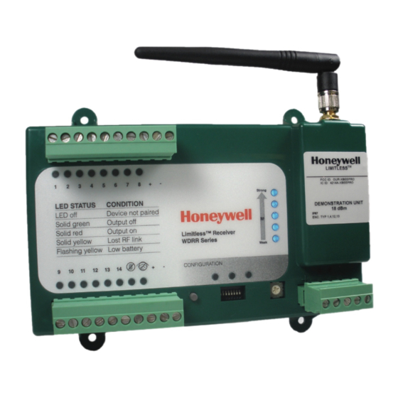
Page 15: Wdrr Feature Overview
Refer to Figure 2. One green LED turns on to indicate power is applied to the WDRR. This occurs when electrical power is supplied to the “+” and “-” power supply terminals Honeywell Sensing and Control 11... -
Page 16: Tri-Color Output Leds
The LED will change state as shown below. RF Link switch position 0-9, A-E Low battery LED status Condition Solid green Acceptable voltage(s) Solid red Low voltage(s) RF Link switch position F Sequence each LED color LED test mode www.honeywell.com/limitless... -
Page 17: Lost Rf Link Output Led
Limitless™ WDRR Receiver to enter many different configuration modes such as set-up, pairing, purge, etc. The configuration LEDs indicate both different modes as well as different states. See Section 6 for more detail. Honeywell Sensing and Control 13... -
Page 18: Electrical Configurations/Connections
Limitless™ input and corresponding chosen output (reference section 5.5). The following chart identifies switch position related to each Limitless™ input/output. Switch position NPN/PNP Input/Output # - RF Link strength displayed None-Normal operation None-LED test mode Note: Factory default switch position is zero. www.honeywell.com/limitless... -
Page 19: Power Supply Connections
Do not apply direct power (supply voltage “+” or “-”) to the “-” terminal or “+” terminal or any of the NPN/PNP type output terminals as damage could occur to the WDRR electronics. Honeywell Sensing and Control 15... -
Page 20: Low Battery Output Connections
- No connection to Output “+” terminal CAUTION Do not apply direct power (supply voltage “+” or “-”) to the “-” terminal or “+” terminal or any of the NPN/PNP type output terminals as damage could occur to the WDRR electronics. www.honeywell.com/limitless... -
Page 21: Configuration Modes And Operations
(within 5 second intervals). This will cause the toggling between the Limitless™ output being “normal” or “reversed”. Once the desired output indication and state has been chosen, wait approximately 5 seconds for all configuration LEDs to turn off before proceeding with other configuration modes. Honeywell Sensing and Control 17... -
Page 22: Pairing Mode
Record the Limitless™ sequence # on identification labels and apply to the Limitless™ housing in desired locations (See Figure 6). Repeat Steps 2-7 to add additional Limitless™ switches. Up to 14 Limitless™ switches can be paired to a single WDRR. www.honeywell.com/limitless... -
Page 23: Figure 3. Limitless™ Switch Housing
Figure 5. Limitless™ Switch with Function Button Depressed Figure 4. Limitless™ WDRR Housing NOTE: Use a blunt object, such as a paper clip or tooth pick to actuate the function switch Figure 6. Limitless™ Switch Label Placement Honeywell Sensing and Control 19... -
Page 24: Purge Mode
12 seconds, but does not wish to put the WDRR into the Factory Reset mode, he/she can immediately release the function button to put the WDRR into Abort mode. The WDRR immediately returns to normal operation. www.honeywell.com/limitless... -
Page 25: Figure 7. Limitless™ Wdrr Operation And Led Functions Chart
. The operation and LED functions are visually depicted and described below. These graphics are also located as a separate file on the installation CD or at www.honeywell.com/sensing. Figure 7. Limitless™ WDRR Operation and LED Functions Chart Honeywell Sensing and Control 21... -
Page 26: Antenna Considerations/Options
Indoor or limited UV stable LG WAMM100R Omni/ with 3,04 m outdoor exposure. UV stable PVC/ UV stable Keyflex BT- SP-010 Straight magnetic [10 ft] Protect against direct RG-174 coax black ABS 1040D mount rain, salt, snow, ice, etc. www.honeywell.com/limitless... -
Page 27: Omni-Directional Antenna Design
The term “omni” may suggest that the antenna radiates power in all directions, but that is not the case. The actual antenna radiation pattern looks more like a toroid (doughnut-shape) as shown in Figure 8. Honeywell Sensing and Control 23... -
Page 28: Antenna Mounting And Considerations
The best performance is achieved when both the Limitless™ input and WDRR monitor antennas are mounted at the same height and in a direct line of sight (LOS) with no obstructions. Generally, the higher the antenna is above ground, the better it performs. Another concern is RF interference, discussed in Section 8.4.3. www.honeywell.com/limitless... -
Page 29: Outdoor Installation Warnings
If anything such as a wire or mast does come in contact with a power line, DON’T TOUCH IT OR ATTEMPT TO MOVE IT. Instead, save a life by calling the power company. • Don’t attempt to erect antennas or towers on windy days. Honeywell Sensing and Control 25... -
Page 30: Antenna Connection, Styles, And Mounting Options
An integral or remote mount antenna can be easily mounted by threading the mating RP-SMA plug of the antenna to the WDRR’s RP-SMA jack. Reference section 8.4.1 for further details on extra environmental protection of RP-SMA connections. Tighten the RP-SMA connection until finger tight. See Figures 11 and 12. www.honeywell.com/limitless... -
Page 31: Antenna Styles And Mounting Options
SMA plug, dBi gain, reverse polarity SMA plug, dBi gain, reverse polarity SMA plug, connector mount 0 dBi straight connector mount 0 dBi straight connector mount (RP-SMA) connector mount (RP-SMA) w/RP-SMA plug w/RP-SMA plug Honeywell Sensing and Control 27... -
Page 32: Figure 14. Adhesive Mount Antenna - Step 1. Pre-Clean The Surface
Figure 14. Adhesive Mount Figure 15. Adhesive Mount Antenna Figure 16. Adhesive Mount Antenna – Step 1. Pre-clean the – Step 2. Peel Protection from Antenna – Step 3. Mount the surface Adhesive Strip Antenna www.honeywell.com/limitless... -
Page 33: Figure 17. Mast Mount Antenna - Tighten Nut On Mounting Bracket
Catalog listings: WAN09RSP & WAN10RSP: These magnetic-mount antennas are designed for mobile applications and can withstand winds at >150 mph. Use Magnetic Mounts with the following antenna catalog listings: WAN01RSP, WAN02RSP,WAN04RSP, WAN05RSP, WAN07RSP, WAN08RSP Honeywell Sensing and Control 29... -
Page 34: Antenna Adjustment Considerations
RF signal. The least RF signal is normally in-line with the top of the antenna, so avoid having the antennas pointed directly toward or directly away from each other. www.honeywell.com/limitless... -
Page 35: Environmental Usage/Concerns
Layer 1 allows the user to remove Layer 2 for connector inspection, antenna replacement, repositioning of the tilt/swivel antenna, etc. In the end, the antenna/cable choice may need to be tested in the actual application conditions to prove suitability. Honeywell Sensing and Control 31... -
Page 36: Outdoor Antenna Installations - Lightning Concerns
RF signal output changes state) indicating the antenna position on the Limitless™ switch and/or WDRR receiver will need to be changed and/or another antenna type should be chosen. The RF Signal LEDs are also useful in indicating the RF Link Strength; refer to Section 5.5 for more information. www.honeywell.com/limitless... -
Page 37: Wdrr Mounting
Also, ensure that the housing is being mounted on a flat surface. Figure 25. Limitless™ WDRR Mounting Tabs Honeywell Sensing and Control 33... -
Page 38: Inspection And Maintenance
Check the LEDs to determine if any are non-functioning (Refer to Section 6.2; Switch position “F”- LED test mode) 10.2 Antenna Inspection and Replacement Periodic inspection • Check antenna or cable connection to WDRR connector to ensure it is tight and bear no signs of damage or corrosion. Replace if necessary per Section 8.3. www.honeywell.com/limitless... -
Page 39: Choosing A Wdrr Series Catalog Listing
Choose a possible integral or remote-mount antenna. Step 5) Sections 8.4 and 8.1 help to determine the antenna material most suitable for use based on the application environment. Also consider the effects of lightning or RF Interference (if applicable). Honeywell Sensing and Control 35... -
Page 40: Quick Start Up & Installation
Country Use Code on the WDRR label. Review Section 1.3 and 2.1 in this manual. If required, contact Honeywell before use of the WDRR in Countries not listed in Table 3 thru 6 in Section 2.1. Suggested Start-up Sections to Review... -
Page 41: Accessories
Low profile straight antenna with 3.0 dBi gain, reverse polarity SMA plug, mobile Low profile dome antenna with 4.0 dBi gain, reverse polarity SMA plug, magnetic mount with 4,57 m [15 ft] cable mobile thru-hole screw mount with 3 m [9.8 ft] cable Honeywell Sensing and Control 37... -
Page 42: Antenna Cable And Mounting Options
Magnetic antenna mounting,100 Series coax cable, reverse polarity SMA plug with WAMM100RSP-010 10 ft of cable 14 INSTALLATION DRAWINGS 14.1 Drawing Availability Complete installation drawings for each listing of the WPMM Series and Limitless™ accessories are available at www.honeywell.com/sensing www.honeywell.com/limitless... -
Page 43: Troubleshooting Guides
Antenna alignment is not Reposition antenna per Section 8.3 acceptable Damage to antenna cable Replace antenna cable per Section 8.3 Loose antenna or cable Check connections and tighten as necessary per connections Section 8.3 Honeywell Sensing and Control 39... - Page 44 (green power LED ON, actuator of Limitless™ switch Replace Limitless™ actuator yellow LEDs OFF) damaged If applicable – actuating head Replace Limitless™ actuating head of Limitless™ switch damaged Limitless™ input(s) internal Replace Limitless™ input(s) electronics damaged Damaged output(s) Replace WDRR www.honeywell.com/limitless...
- Page 45 +1-305-805-8188 +1-305-883-8257 Fax While we provide application assistance personally, USA/Canada +1-800-537-6945 through our literature and the Honeywell web site, it is up to +1-815-235-6847 the customer to determine the suitability of the product in +1-815-235-6545 Fax the application. Specifications may change without notice. The information we supply is believed to be accurate and reliable as of this printing.