Table of Contents
Advertisement
Quick Links
Table of Contents
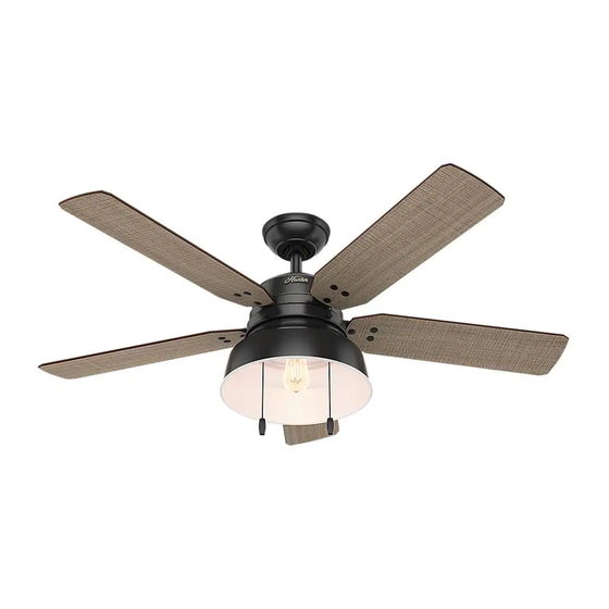
Congratulations on purchasing
your new Hunter® ceiling fan! It will
provide comfort and performance
in your home or office for many
years. This installation and operation
manual contains complete
instructions for installing and
operating your fan.
We are proud of our work and
appreciate the opportunity to
supply you with the best ceiling fan
available anywhere in the world.
To register your fan, please visit:
www.HunterFan.com/register
Save your receipt for proof of purchase.
What to Expect with
Your Installation
Tools Needed
30 inches
7 feet
2
Downrod
6
Switch Housing
Light Kit
13
1
M3624-01 • 10/11/16 • © 2016 Hunter Fan Company
Mounting Options
Ladder
3
Wiring
Canopy
9
Maintenance
& Cleaning
15
www.HunterFan.com
1.888.830.1326
Ceiling Bracket
4
5
Blades
12
11
Troubleshooting
?
?
?
16
17
Advertisement
Table of Contents

Related Manuals for Hunter Mill Valley 59307


Summary of Contents for Hunter Mill Valley 59307
- Page 1 To register your fan, please visit: www.HunterFan.com/register Save your receipt for proof of purchase. Maintenance Switch Housing Light Kit & Cleaning Troubleshooting M3624-01 • 10/11/16 • © 2016 Hunter Fan Company...
-
Page 2: What To Expect With Your Installation
This device complies with Part 15 of the FCC Rules. Operation is subject to the following two conditions: (1) This device may not cause harmful interference, and (2) this device must accept any interference received, including interference that may cause undesired operation. M3624-01 • 10/11/16 • © 2016 Hunter Fan Company... -
Page 3: Tools Needed
The symbols can be used to identify the appropriate hardware for each step. Power Drill 9/64” Drill Bit Screwdrivers (optional) (optional) If mounting to a support structure, you will also need these tools. M3624-01 • 10/11/16 • © 2016 Hunter Fan Company... -
Page 4: Mounting Options
You need BOTH You need ONLY a Longer a Longer Downrod & Downrod an Angled Mounting Kit *most common M3624-01 • 10/11/16 • © 2016 Hunter Fan Company... -
Page 5: Ceiling Bracket
To avoid possible electrical shock, before 1-888-830-1326. installing your fan, disconnect the power by turning off the circuit breakers to the outlet Refer to warning w.1 on pg. 2 box associated with the wall switch location. M3624-01 • 10/11/16 • © 2016 Hunter Fan Company... - Page 6 Steps 1-5 to remove standard downrod pipe Longer Downrod for angled ceilings or ceilings 10’ or higher Shorter Downrod for fans installed close to ceiling Steps 6-10 to reassemble with new pipe M3624-01 • 10/11/16 • © 2016 Hunter Fan Company...
- Page 7 4-5 full turns) until it stops. with pliers. DO NOT can be inserted. from the top of the downrod. HAND TIGHTEN. 8” 3/8” If the setscrew is not tightened securely, the fan may fall. M3624-01 • 10/11/16 • © 2016 Hunter Fan Company...
- Page 8 Put the wires and downrod through the canopy. Let the canopy sit loosely on top CANOPY OR WIRES. Place the downrod of the fan. ball into the slot in the ceiling bracket. Note: Fan style may vary. M3624-01 • 10/11/16 • © 2016 Hunter Fan Company...
- Page 9 Spread the wires apart, with the grounded wires on one side of Refer to CAUTION c.1 on pg. 2 the outlet box and the ungrounded wires on the other side of the outlet box. M3624-01 • 10/11/16 • © 2016 Hunter Fan Company...
- Page 10 Spread the wires apart, with the grounded wires on one side of Refer to CAUTION c.1 on pg. 2 the outlet box and the ungrounded wires on the other side of the outlet box. M3624-01 • 10/11/16 • © 2016 Hunter Fan Company...
- Page 11 Insert the two canopy screws lifted into place, the canopy fits into the screw holes are aligned. found in the hardware bag. the hanging bracket as shown. Note: Fan style may vary. M3624-01 • 10/11/16 • © 2016 Hunter Fan Company...
- Page 12 M3624-01 • 10/11/16 • © 2016 Hunter Fan Company...
-
Page 13: Switch Housing
You will need them later. attached to the mounting plate. Failure to properly secure all 3 assembly screws could result in the switch Note: Fan style may vary. housing fixture falling. M3624-01 • 10/11/16 • © 2016 Hunter Fan Company... - Page 14 Make sure the lower switch housing is securely attached to the upper switch housing. Failure to properly secure all three assembly screws could result in the light fixture falling. M3624-01 • 10/11/16 • © 2016 Hunter Fan Company...
-
Page 15: Light Kit
Exceeding the wattage limit marked on the MAX wattage sticker affixed to the light socket(s) may result in fire hazard or improper operation. M3624-01 • 10/11/16 • © 2016 Hunter Fan Company... -
Page 16: Maintenance And Cleaning
- move the reverse switch brushes or cloths to prevent to the opposite position. scratching. Cleaning products type and wattage. may damage the finishes. M3624-01 • 10/11/16 • © 2016 Hunter Fan Company... -
Page 17: Troubleshooting
• Turn off power from the circuit breaker, then loosen the canopy and check all the connections according to the wiring diagram on page 9-10. • Check the plug connection in the switch housing. M3624-01 • 10/11/16 • © 2016 Hunter Fan Company...