Table of Contents
Advertisement
Quick Links
This user's guide describes the characteristics, operation, and use of the PGA112 evaluation module
(EVM). It covers all pertinent areas involved to properly use this EVM board. The document includes the
physical printed circuit board layout, schematic diagrams, and circuit descriptions.
......................................................................................................................
1
2
3
4
5
1
2
3
4
5
6
7
8
9
10
11
12
13
14
15
16
17
1
2
3
4
5
Microsoft, Windows are registered trademarks of Microsoft Corporation.
SPI is a trademark of Motorola Inc.
2
I
C is a trademark of NXP Semiconductors.
All other trademarks are the property of their respective owners.
SBOU073 - February 2009
Submit Documentation Feedback
................................................................................................................
.............................................................................................
..............................................................................................
.............................................................................................................
................................................................................
.............................................................................................
.....................................................................................
..........................................................................................
......................................................................................
...........................................................................................
.........................................................................................
...........................................................................................
...............................................................................................
..................................................................................
............................................................................................
............................................................................................
.....................................................................................
..........................................................................................
................................................................................
....................................................................................
..........................................................................................
PGA112 Evaluation Module
Contents
List of Figures
.........................................................................
....................................................................
List of Tables
...............................................
............................................
User's Guide
SBOU073 - February 2009
........................................
PGA112 Evaluation Module
2
4
9
16
23
3
4
5
6
9
10
11
12
13
14
16
17
18
18
19
20
22
7
8
15
15
23
1
Advertisement
Table of Contents

Related Manuals for Texas Instruments PGA112


Summary of Contents for Texas Instruments PGA112
-
Page 1: Table Of Contents
SBOU073 – February 2009 PGA112 Evaluation Module This user’s guide describes the characteristics, operation, and use of the PGA112 evaluation module (EVM). It covers all pertinent areas involved to properly use this EVM board. The document includes the physical printed circuit board layout, schematic diagrams, and circuit descriptions. -
Page 2: Overview
PGA112 and PGA113 programmable gain amplifiers. For a more detailed description of the PGA112 family, please refer to the product data sheet (SBOS424) available from the Texas Instruments web site at http://www.ti.com. Additional support documents are listed in the section of... -
Page 3: Hardware Included With The Pga112Evm
Overview www.ti.com Figure 1. Hardware Included with the PGA112EVM SBOU073 – February 2009 PGA112 Evaluation Module Submit Documentation Feedback... -
Page 4: System Setup
Optional External DC and AC source connection Power Optional DVM or PGA112/113 USB DAQ Oscilloscope Test Board Platform connection Figure 2. PGA112EVM Hardware Setup PGA112 Evaluation Module SBOU073 – February 2009 Submit Documentation Feedback... -
Page 5: Pga112_Test_Board Block Diagram
PGA112_Test_Board schematic. The J1 connector ports the analog-to-digital converters (ADCs), digital-to analog converters (DACs), and SPI™ control. The J2 connector ports the control bits for the input and output switches. SBOU073 – February 2009 PGA112 Evaluation Module Submit Documentation Feedback... -
Page 6: Pga112_Test_Board Schematic
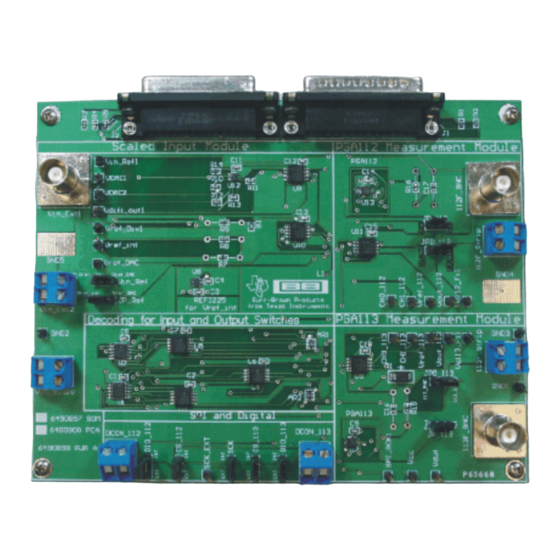
System Setup www.ti.com Figure 4. PGA112_Test_Board Schematic PGA112 Evaluation Module SBOU073 – February 2009 Submit Documentation Feedback... -
Page 7: Signal Definition Of J1 (25-Pin Male Dsub) On Pga112_Test_Board
ADS2– ADS2– I2C_SCK — I2C_SDA2 — ONE_WIRE — I2C_SCK_ISO — I2C_SDA_ISO — XTR_LOOP+ — XTR_LOOP– — INA– — +15V — –15V — SPI_SCK SPI_SCK SPI_CS1 SPI_CS1 SPI_DOUT SPI_DOUT SPI_DIN1 SPI_DIN1 SBOU073 – February 2009 PGA112 Evaluation Module Submit Documentation Feedback... -
Page 8: Signal Definition Of J2 (25-Pin Female Dsub) On Pga112_Test_Board
CTRL6 CTRL6 CTRL7 CTRL7 CTRL8 CTRL8 MEAS1 — MEAS2 — MEAS3 — MEAS4 — MEAS5 — MEAS6 — MEAS7 — MEAS8 — SPI_SCK SPI_SCK SPI_CS2 SPI_CS2 SPI_DOUT2 SPI_DOUT2 SPI_DIN2 SPI_DIN2 PGA112 Evaluation Module SBOU073 – February 2009 Submit Documentation Feedback... -
Page 9: Pga112Evm Hardware Setup
Figure 5 shows the block diagram for the USB DAQ Platform. This platform is a general-purpose data acquisition system that is used on several different Texas Instruments evaluation modules. The details of its operation are included in a separate document (available for download at www.ti.com). -
Page 10: Typical Hardware Connections
The PGA112EVM hardware setup involves connecting the two PCBs of the EVM together, applying power, and connecting an external shunt and load. The external connections may be the real-world system that the PGA112 will be incorporated into. Figure 6 shows the typical hardware connections. -
Page 11: Connecting The Two Evm Pcbs
(as shown in Figure 7). Make sure that the two connectors are completely pushed together; that is, loose connections may cause intermittent operation. Figure 7. Connecting the Two EVM PCBs SBOU073 – February 2009 PGA112 Evaluation Module Submit Documentation Feedback... -
Page 12: Connecting Power To The Evm
PGA112EVM Hardware Setup www.ti.com Connecting Power After the two parts of the PGA112 EVM are connected, as shown in Figure 8, connect the power to the EVM. Always connect power before connecting the USB cable. If you connect the USB cable before connecting the power, the computer will attempt to communicate with an unpowered device that will not be able to respond. -
Page 13: Connecting The Usb Cable
In some cases, the Windows Add Hardware Wizard will pop up. If this prompt occurs, allow the system device manager to install the Human Interface Drivers by clicking Yes when requested to install drivers. Figure 9. Connecting the USB Cable SBOU073 – February 2009 PGA112 Evaluation Module Submit Documentation Feedback... -
Page 14: Pga112Evm Default Jumper Settings
_PGA pin; doing so will allow you to use higher gains because the voltage at the V pin of the PGA112/113 will subtract from your input voltage. Also, you may want to debug your own SPI commands. You can easily do this debugging by moving the DIO_112/113, CS_112/113, and SCK pins from the default INT positions to the external position EXT. -
Page 15: Pga112_Test_Board Jumper Functions
2.5V reference and a variable DAC reference (V ) for the REF_DAC REF_DAC PGA112 or the PGA113. This jumper allows the user to reference the PGA112 or JP_112/JP_113 PGA113 to ground or a variable voltage reference. JP0_112/JP0_113 112_Strip/113_Strip User-selectable output as BNC or wire strip. -
Page 16: Pga112 Software Overview
Step 4. To remove the application, use the Windows Control Panel utility, Add/Remove Software. Starting the PGA112EVM Software The PGA112 software can be operated through the Windows Start menu. From Start, select All Programs; then select the PGA112EVM program. Figure 11 shows how the software should appear if the EVM is functioning properly. -
Page 17: Pga112Evm Software-No Communication With The Usb Daq Platform
PGA112/113. The PGA112/113 tabs allow you to individually configure the gain and select the channels to read at the output of either the PGA112 or PGA113. The Bit Read Tables tab shows (in red) which channels and gains are enabled. -
Page 18: Scaled Inputs To Pga112/113
Figure 13. Scaled Inputs to PGA112/113 This tab has the following controls: • Diff Amp Input allows user to program a very small voltage input to the PGA112/113 device, so that higher gains can be more easily evaluated • The Resistor Divider Input allows the user to create a unique input from an external source and the internal 2.5V reference with a 0V to 5V output. -
Page 19: Pga112/113 Bit Read Tables
Figure 15. PGA112/113 Bit Read Tables This tab has the following controls: • Show the selection of either the PGA112 or the PGA113 • Indicate which SPI bits are enabled for the selected device with a '1' • Translation tables at the bottom of the window show the corresponding scope and binary gain SBOU073 –... -
Page 20: Pga112 Measurement Module Tab
• Select either a 3V or 5V supply, and cycle the power for the ADS1100 measurement ADC • Select the PGA112 (or PGA113) output, 2.5V reference, CH0 input, or CH1 input to be read using the ADS1100 PGA112 Evaluation Module SBOU073 –... - Page 21 Gain = V ´ Note that the PGA112 reference acts as an input subtraction term rather than a dc shift at the output. This feature makes it easier to evaluate the accuracy of higher gains. To measure the gain of the PGA112, follow this procedure: Step 1.
-
Page 22: Pga112/113 Self-Test Function
PGA112 Software Overview www.ti.com PGA112/113 Self-Test The Self-Test function is illustrated in Figure 17. This function can be used to..Figure 17. PGA112/113 Self-Test Function PGA112 Evaluation Module SBOU073 – February 2009 Submit Documentation Feedback... -
Page 23: Bill Of Materials
INSTRUMENTS (VA) V REF3225 SOT23-6 TEXAS REF3225AIDBVT $2.14 $8.56 INSTRUMENTS (VA) V SN74HC4066D U8 U9 U10 U IC QUAD TEXAS SN74HC4066DBR $0.14 ..56 BI-LAT INSTRUMENTS ANALOG SW (VA) V 14-SSOP SBOU073 – February 2009 PGA112 Evaluation Module Submit Documentation Feedback... - Page 24 -na- Standoffs, Hex , Keystone 2203K 2.25 4-40 Threaded, 0.500" length, 0.250" OD, Aluminum Iridite Finish Screws -na- SCREW Building PMSSS 440 0025 4.13 4.13 MACHINE PHIL Fasteners 4-40X1/4 SS PGA112 Evaluation Module SBOU073 – February 2009 Submit Documentation Feedback...
- Page 25 EVALUATION BOARD/KIT IMPORTANT NOTICE Texas Instruments (TI) provides the enclosed product(s) under the following conditions: This evaluation board/kit is intended for use for ENGINEERING DEVELOPMENT, DEMONSTRATION, OR EVALUATION PURPOSES ONLY and is not considered by TI to be a finished end-product fit for general consumer use. Persons handling the product(s) must have electronics training and observe good engineering practice standards.
- Page 26 IMPORTANT NOTICE Texas Instruments Incorporated and its subsidiaries (TI) reserve the right to make corrections, modifications, enhancements, improvements, and other changes to its products and services at any time and to discontinue any product or service without notice. Customers should obtain the latest relevant information before placing orders and should verify that such information is current and complete.