Table of Contents
Advertisement
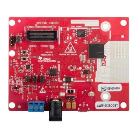
AWR1642 Evaluation Module (AWR1642BOOST)
The AWR1642 BoosterPack™ from Texas Instruments™ is an easy-to-use evaluation board for the
AWR1642 mmWave sensing device, with direct connectivity to the microcontroller (MCU) LaunchPad™
Development Kit. The BoosterPack contains everything required to start developing software for on-chip
C67x DSP core and low-power ARM
debugging as well as onboard buttons and LEDs for quick integration of a simple user interface.
1
1.1
1.2
1.3
......................................................................................................................
2
2.1
2.2
2.3
2.4
2.5
2.6
2.7
3
3.1
3.2
4
5
6
7
8
Trademarks
BoosterPack, Texas Instruments, LaunchPad, Code Composer Studio are trademarks of Texas
Instruments.
ARM is a registered trademark of ARM Limited.
Windows is a registered trademark of Microsoft Corporation.
All other trademarks are the property of their respective owners.
SWRU508B - May 2017 - Revised April 2018
Submit Documentation Feedback
Single-Chip mmWave Sensing Solution
R4F controllers, including onboard emulation for programming and
®
...............................................................................................................
..........................................................................................................
.......................................................................................................
..........................................................................................................
.......................................................................................................
.................................................................................................
..........................................................................................................
.....................................................................................................
.............................................................................................................
...................................................................................
.........................................................................................
...........................................................................................................
..................................................................................................
.............................................................................................
....................................................................................................
............................................................................................................
AWR1642 Evaluation Module (AWR1642BOOST) Single-Chip mmWave
Copyright © 2017-2018, Texas Instruments Incorporated
SWRU508B - May 2017 - Revised April 2018
Contents
...........................................................
........................................................................
User's Guide
2
2
2
2
3
5
6
6
10
............................
11
11
13
16
16
16
17
18
18
19
19
1
Sensing Solution
Advertisement
Table of Contents

Related Manuals for Texas Instruments AWR1642


Summary of Contents for Texas Instruments AWR1642
-
Page 1: Table Of Contents
AWR1642 Evaluation Module (AWR1642BOOST) Single-Chip mmWave Sensing Solution The AWR1642 BoosterPack™ from Texas Instruments™ is an easy-to-use evaluation board for the AWR1642 mmWave sensing device, with direct connectivity to the microcontroller (MCU) LaunchPad™ Development Kit. The BoosterPack contains everything required to start developing software for on-chip... -
Page 2: Getting Started
< 3 m. 1.3.1 mmWave Proximity Demo TI provides sample demo codes to easily get started with the AWR1642 evaluation module (EVM) and to experience the functionality of the AWR1642 radar sensor. For details on getting started with these demos, see www.ti.com/tool/mmwave-sdk. -
Page 3: Hardware
5-V Power 60-pin HD CAN-FD Connector Connector GPIO1_SW NRST_SW SOP Controls Figure 1. EVM (Front) SWRU508B – May 2017 – Revised April 2018 AWR1642 Evaluation Module (AWR1642BOOST) Single-Chip mmWave Sensing Solution Submit Documentation Feedback Copyright © 2017–2018, Texas Instruments Incorporated... - Page 4 Connector (J6) Connector (J5) PMIC Micro USB Connector Heat Sink Area Figure 2. EVM (Rear) AWR1642 Evaluation Module (AWR1642BOOST) Single-Chip mmWave SWRU508B – May 2017 – Revised April 2018 Sensing Solution Submit Documentation Feedback Copyright © 2017–2018, Texas Instruments Incorporated...
-
Page 5: Block Diagram
PGOOD signal to MCU for power sequencing Copyright © 2017, Texas Instruments Incorporated Figure 3. Block Diagram SWRU508B – May 2017 – Revised April 2018 AWR1642 Evaluation Module (AWR1642BOOST) Single-Chip mmWave Sensing Solution Submit Documentation Feedback Copyright © 2017–2018, Texas Instruments Incorporated... -
Page 6: Power Connections
TI MCU LaunchPads. While connecting the BoosterPack to other LaunchPads, ensure the pin-1 orientation is correct by matching the 3V3 and 5-V signal marking on the boards. Figure 5. 20-Pin BoosterPack Connectors AWR1642 Evaluation Module (AWR1642BOOST) Single-Chip mmWave SWRU508B – May 2017 – Revised April 2018 Sensing Solution Submit Documentation Feedback Copyright ©... - Page 7 SYNC_OUT PMIC CLK OUT Voltage input to the GPADC available on the AWR1642. Indicates the state of the onboard VIO supply for the AWR device coming from the onboard PMIC. A HIGH on the PGOOD signal (3.3 V) indicates the supply is stable. Because the I/Os are not failsafe, the MCU must not drive any I/O signals to the AWR device before this I/O supply is stable to avoid leakage current into the I/Os.
- Page 8 HD connector, and Table 3 provides the connector information. Figure 6. HD Connector AWR1642 Evaluation Module (AWR1642BOOST) Single-Chip mmWave SWRU508B – May 2017 – Revised April 2018 Sensing Solution Submit Documentation Feedback Copyright © 2017–2018, Texas Instruments Incorporated...
- Page 9 Because the I/Os are not failsafe, the MCU must not drive any I/O signals to the AWR device before this I/O supply is stable to avoid leakage current into the I/Os. SWRU508B – May 2017 – Revised April 2018 AWR1642 Evaluation Module (AWR1642BOOST) Single-Chip mmWave Sensing Solution Submit Documentation Feedback...
-
Page 10: Pc Connection
COM ports, users must install the EMU pack available at ® Emulation Software Package. AWR1642 Evaluation Module (AWR1642BOOST) Single-Chip mmWave SWRU508B – May 2017 – Revised April 2018 Sensing Solution Submit Documentation Feedback Copyright © 2017–2018, Texas Instruments Incorporated... -
Page 11: Connecting The Boosterpack To The Launchpad Or The Mmwave-Devpack
20-pin connectors. The connectors do not have a key to prevent the misalignment of the pins or reverse connection. Hence, care must be taken to ensure reverse mounting does not take place. On the AWR1642 BoosterPack, TI has provided 3V3 markings near pin 1, shown in Figure 9. - Page 12 (H-plane Phi = 0 degrees) and elevation plane (E-plane Phi = 90 degrees) is shown by Figure Figure 11. Antenna Pattern AWR1642 Evaluation Module (AWR1642BOOST) Single-Chip mmWave SWRU508B – May 2017 – Revised April 2018 Sensing Solution Submit Documentation Feedback...
-
Page 13: Jumpers, Switches, And Leds
Sense-on-Power (SOP) Jumpers The AWR1642 device can be set to operate in three different modes based on the state of the SOP lines. These lines are sensed only during boot up of the AWR device. The state of the device is detailed by... - Page 14 LED information. Table 5. Switch and LED Information Reference Usage Comments Used to RESET the AWR1642 device. This signal is also brought out on the 20- pin connector and 60-pin HD connector so RESET an external processor can control the AWR device.
- Page 15 Selection Between SPI and CAN Interface The SPI and CAN interface are muxed on the same lines on the AWR1642 device. Based on the configuration, the user can select if the pins E14 and D13 must be connected to the 20-pin/HD connectors to provide the SPI interface OR to the onboard CANFD PHY (U3).
-
Page 16: Design Files And Software Tools
Files. Software, Development Tools, and Example Code To enable quick development of end applications on the C67x DSP and R4F core in the AWR1642, TI provides a software development kit (SDK) that includes demo codes, software drivers, emulation packages for debug, and more. These can be found at mmwave-sdk. -
Page 17: Design Revision History
Serial flash part number updated to MX25V1635FZNQ Added series resisters on I2C lines. Removed the series diode on the NRST signal. SWRU508B – May 2017 – Revised April 2018 AWR1642 Evaluation Module (AWR1642BOOST) Single-Chip mmWave Sensing Solution Submit Documentation Feedback Copyright © 2017–2018, Texas Instruments Incorporated... -
Page 18: Mechanical Mounting Of Pcb
The field of view of the radar sensor is orthogonal to the PCB. To enable easy measurements on the sensing objects on the horizontal plane, the PCB can be mounted vertically. The L-brackets provided with the AWR1642 EVM kit, along with the screws and nuts help in the vertical mounting of the EVM. Figure 21 shows how the L-brackets can be assembled. -
Page 19: Regulatory Information
Regulatory Information The AWR1642 evaluation module (AWR1642BOOST) is in compliance with Directive 2014/53/EU. The full text of TI's EU Declaration of Conformity is available at the following link: http://www.ti.com/tool/awr1642boost. The compliance has been verified in the operating bands of 76- to 77-GHz and 77- to 81-GHz. - Page 20 Updated CAN Interface Connector section................. • Added Selection Between SPI and CAN Interface section....................• Added Design Revision History section. Revision History SWRU508B – May 2017 – Revised April 2018 Submit Documentation Feedback Copyright © 2017–2018, Texas Instruments Incorporated...
- Page 21 IMPORTANT NOTICE FOR TI DESIGN INFORMATION AND RESOURCES Texas Instruments Incorporated (‘TI”) technical, application or other design advice, services or information, including, but not limited to, reference designs and materials relating to evaluation modules, (collectively, “TI Resources”) are intended to assist designers who are developing applications that incorporate TI products;...
- Page 22 Mouser Electronics Authorized Distributor Click to View Pricing, Inventory, Delivery & Lifecycle Information: Texas Instruments AWR1642BOOST...