Table of Contents
Advertisement
Advertisement
Table of Contents

Related Manuals for Delta AX-8 Series


Summary of Contents for Delta AX-8 Series
- Page 1 AX-8 Series User Guide www.deltaww.com...
- Page 2 AX-8 series provides 35 kinds of homing methods, point-to point position control, speed control, torque control, multi-axis interpolation, Robot and CNC etc. The complete motion control functions of the AX-8 series products are able to meet the needs of the diverse industry. This product optimally integrates the operations of multi-axis synchronous motion control, enabling easier assembly, better stability, and more flexible expansion capabilities.
- Page 3 (This page is intentionally left blank.)
-
Page 4: Table Of Contents
2.3.8 WatchDog On/Off Switch ·········································································· 2-13 2.4 Wiring Example ····························································································· 2-14 2.4.1 AX-8 Series Wiring for Input Point Connection With External Devices ················· 2-14 2.4.2 AX-8 Series Wiring for Output Point Connection With External Devices ·············· 2-15 2.4.3 AX-8SeriesEncoder Wiring ········································································ 2-17 Product Installation 3.1 Hung Installation ······························································································... - Page 5 BIOS 4.1 BIOS Operation and Setting ················································································4-1 4.1.1 Main ········································································································4-3 4.1.2 Advanced ·································································································4-4 4.1.3 WatchDot ·································································································4-5 4.1.4 Chipset ····································································································4-6 4.1.5 Security ································································································· 4-11 4.1.6 Boot ······································································································ 4-12 4.1.7 Save & Exit ····························································································· 4-13 System Operation and Settings 5.1 Setting and Releasing of the Write Protection UWF Function······································ 5-2 5.1.1 Using the PAC_Tool to Perform Write Protection UWF Operations ························5-3 5.1.2 Read Current Write Protection Status ·····························································5-3 5.1.3 Enabling Write Protection ·············································································5-4...
-
Page 6: Product Inspection
Model Explanation This chapter mainly introduces the product inspection and product model description, as well as the electrical safety precautions of the AX-8 series product. Read this chapter before using the product to understand related contents. 1.1 Product Inspection ··············································································· 1-2 1.2 Model Description ················································································... - Page 7 Product Inspection and Model Description AX-8 Series User Manual 1.1 Product Inspection Users please verify the integrity of this product package, and confirm whether all the following items and accessories are complete: Host Product Installation Manual Accessories (As shown in Figure 1.1.1) Figure 1.1.1 Accessory Diagrams...
- Page 8 AX-8 Series User Manual Product Inspection and Model Description 1.2 Model Description Item Description Product type AX = AX Series Standalone Controller 7, 8, 9 = PC-based Processor 1, 2, 3, 4, 5, 6 = PLC-based (1, 2 = Compact; 3, 4, 5 = Middle; 6 = High) Number of Axes 08 = 8 axes;...
-
Page 9: Electrical Safety Precautions
If you are unsure of the supplied voltage value of your region, please consult your local power company staff. If the power supply is damaged, do not attempt to fix it by yourself. Please contact Delta’s professional technical service staff or the dealer. ... -
Page 10: Specifications And Product Interface
2.3.7 Protocol Port Bus Communication Interface ······································· 2-12 2.4 Wiring Examples ··············································································· 2-14 2.4.1 AX-8 Series Wiring for Input Point Connection With External Devices······ 2-14 2.4.2 AX-8 Series Wiring for Output Point Connection With External Devices ·· 2-15 2.4.3 AX-8SeriesEncoder Wiring ···························································· 2-17... -
Page 11: Electrical Specifications
Product Specifications and Part Descriptions AX-8 Series User Manual 2.1 Electrical Specifications AX-8 Item Intel Celeron J1900 Quad Core 2.00GHz, Processor up to 2.42GHz BIOS AMI BIOS Processor System Memory On Board DDR3L-1333 4GB Power Loss Retentive 128 KB MRAM... - Page 12 AX-8 Series User Manual Product Specifications and Part Descriptions AX-8 Item Toff ≤ 150 ns Display Interface Display Interface 1 x HDMI 1.4a Specifications Expansion Interface Expansion Interface 1 x SD Card Slot (SD card 3.0 Interface) Specifications 1 x M.2 2242 type B&M-key SATA SSD...
-
Page 13: External Dimensions
Product Specifications and Part Descriptions AX-8 Series User Manual 2.2 External Dimensions AX-8 Series Model External Dimensions: 54.2 x 141 x 137.4 mm (W x H x D) Unit:mm... -
Page 14: Part Names And Port Descriptions
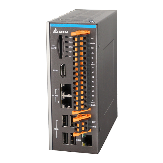
AX-8 Series User Manual Product Specifications and Part Descriptions 2.3 Part Names and Port Descriptions AX-8 series model host port illustration diagram and descriptions. Introduction to Part Names and Port Functions: Description Description SD Card Slot Status Indicator Reset Switch RS-485/422;Encoder;... -
Page 15: Hdmi Display Port
Product Specifications and Part Descriptions AX-8 Series User Manual 2.3.1 HDMI Display Port HDMI display port pin illustration diagram and pin descriptions are as follows. (1) HDMI Display Port (2) HDMI Cable Port HDMI Pin Definitions: Description Description TX+_2 HDMI_GND... -
Page 16: Ethernet Port
AX-8 Series User Manual Product Specifications and Part Descriptions 2.3.2 Ethernet Port Gigabit LAN network port pin illustration diagram and its pin descriptions are as follows. (1) Gigabit LAN Network Port (2) Network Cable Connector Gigabit LAN Network Port Pin Definitions:... -
Page 17: Usb Port
Product Specifications and Part Descriptions AX-8 Series User Manual 2.3.3 USB Port USB 2.0 port pin illustration diagram and its pin descriptions are as follows. (1) USB2.0 (2) USB Signal Cable Connector USB 2.0 Port Pin Definitions: Description Description Power (+5V) -
Page 18: Status Indicator
AX-8 Series User Manual Product Specifications and Part Descriptions 2.3.4 Status Indicator The following is the status indicator location map and description. Status Indicator Definitions: Mark Description Mark Description Power Indicator Bus 1 Indicator Operation Indicator Bus 2 Indicator Error Indicator... -
Page 19: Rs-485/422 Encoder And Gpio Port
Product Specifications and Part Descriptions AX-8 Series User Manual 2.3.5 RS-485/422 Encoder and GPIO Port RS-485/RS-422 encoder GPIO port pin illustration diagram and its pin descriptions are as follows. (1) RS-485/RS-422 Encoder and GPIO Port (2) Port Cable Connector RS-485/RS-422 Encoder and GPIO Pin Definitions:... -
Page 20: Power Port
AX-8 Series User Manual Product Specifications and Part Descriptions 2.3.6 Power Port Power port pin illustration diagram and its pin descriptions are as follows. (1) Power Port (2) Power Port Cable Connector Power Port Pin Definitions: Description Description Frame Ground (FG) -
Page 21: Protocol Port Bus Communication Interface
Product Specifications and Part Descriptions AX-8 Series User Manual 2.3.7 Protocol Port Bus Communication Interface EtherCAT port pin illustration diagram and its pin descriptions are as follows. (1) EtherCAT Port (2) Network Cable Connector EtherCAT Port Pin Descriptions: Description Description... -
Page 22: Watchdog On/Off Switch
AX-8 Series User Manual Product Specifications and Part Descriptions 2.3.8 WatchDog On/Off Switch The watchdog function switch is as follows (1) Function Enable;(2) Function Disable User can switch on/off watchdog function on the bottom of AX-8. When Watchdog function is enable and there is a system crash, the watchdog timer will send out the reset signal to let system return normal operation. -
Page 23: Wiring Example
Product Specifications and Part Descriptions AX-8 Series User Manual 2.4 Wiring Examples 2.4.1 AX-8 Series Wiring for Input Point Connection With External Devices SINK Type Wiring: (AX-8 J3 SINK Power supply Internal circuit SINK 1 2 3 24V COM 3.3V... -
Page 24: Series Wiring For Output Point Connection With External Devices
AX-8 Series User Manual Product Specifications and Part Descriptions 2.4.2 AX-8 Series Wiring for Output Point Connection With External Devices SINK Type Wiring: (AX-8 (1) Application 1: Relay Type IO Power Supply SINK IO24V 24VDC IOGND Relay IOGND Internal Circuit... - Page 25 Product Specifications and Part Descriptions AX-8 Series User Manual SOURCE Type Wiring: (AX-8 Application 1: Relay Type IO Power Supply SOURCE IO24V 24VDC IOGND IO24V Relay Internal Circuit Relay FBD : Flyback Diode IOGND Application 2: External equivalent load resistance type.
-
Page 26: Ax-8Seriesencoder Wiring
AX-8 Series User Manual Product Specifications and Part Descriptions 2.4.3 AX-8SeriesEncoder Wiring Encoder Signal Wiring Diagram Internal Circuit 2-17... -
Page 27: Product Installation
Product Installation This chapter explains the installation method of the AX-8 series host and the installation method of storage devices. 3.1 Hung Installation ·················································································· 3-2 3.2 SD Card Installation ············································································· 3-3... -
Page 28: Hung Installation
Product Installation AX-8 Series User Manual 3.1 Hung Installation As shown in the diagram, rotate the host to its back and use the M3 pan head screws to lock the fixture component onto the host body, and use the wall mount to fix the two upper and lower holes of the fixture in place. -
Page 29: Sd Card Installation
AX-8 Series User Manual Product Installation 3.2 SD Card Installation nsert the SD card into the slot according to the direction illustrated in the diagram. - Page 30 Product Installation AX-8 Series User Manual (This page is left blank on purpose.)
- Page 31 BIOS This chapter provides BIOS related settings and descriptions for the AX-8 series. 4.1 BIOS Operations and Settings ································································ 4-2 4.1.1 Main ··························································································· 4-3 4.1.2 Advanced ····················································································· 4-4 4.1.3 WatchDog ···················································································· 4-5 4.1.4 Chipset ························································································ 4-6 4.1.5 Security ······················································································4-11 4.1.6 Boot ·························································································· 4-12...
-
Page 32: Bios Operation And Setting
BIOS AX-8 Series User Manual 4.1 BIOS Operations and Settings When “Press Del or F2 to Enter Setup” is displayed during boot up, press the Del button or F2 button to enter the BIOS setting screen as shown in Figure 4.1.1. -
Page 33: Main
AX-8 Series User Manual BIOS 4.1.1 Main The Main option of the BIOS includes Total Memory and System Language, etc. as shown in the figure below: Figure 4.1.1.1 Item Default Value Description System Language English System Date Sets System Date... -
Page 34: Advanced
BIOS AX-8 Series User Manual 4.1.2 Advanced The Advanced option of the BIOS includes HW Monitor, etc. as shown in the figure below. Figure 4.1.2.1 Default Item Description Value H/W Monitor Hardware Monitor IDE Configuration IDE Device Configuration Miscellaneous Configuration MISC Configuration LPSS &... -
Page 35: Watchdot
AX-8 Series User Manual BIOS 4.1.3 WatchDog The WatchDog timer function is used to determine whether the system is operating normally; it is activated at fixed intervals to check the system. If the result displayed is abnormal, it will restart the system. -
Page 36: Chipset
BIOS AX-8 Series User Manual 4.1.4 Chipset The Chipset option of the BIOS includes the North Bridge and South Bridge, etc., as shown in the figure below. Figure 4.1.4.1 Item Default Value Description North Bridge North Bridge South Bridge South Bridge... - Page 37 AX-8 Series User Manual BIOS North Bridge The North Bridge option of the BIOS includes Intel IGD Configuration and Max TOLUD, etc., as shown in the figure below: Figure 4.1.4.2 Item Default Value Description Intel IGD Configuration Intel Built-in Display Chipset Configuration...
- Page 38 BIOS AX-8 Series User Manual South Bridge The South Bridge option of the BIOS includes USB Configuration, etc., as shown in the figure below: Figure 4.1.4.3 Item Default Value Description Azalia HD Audio Azalia Audio Configuration USB Configuration USB Configuration...
- Page 39 AX-8 Series User Manual BIOS Automatic Booting When Power is Connected Steps to enable or disable the automatic booting when power is connected are as described below: 1. Under the Chipset screen, select the South Bridge option as shown in Figure 4.1.4.4.
- Page 40 BIOS AX-8 Series User Manual Figure 4.1.4.5 4-10...
-
Page 41: Security
AX-8 Series User Manual BIOS 4.1.5 Security The Security option of the BIOS includes the Administrator Password and User Password, etc., as shown in Figure 4.1. 5.1: Figure 4.1.5.1 Default Item Description Value Set/Change System Administrator Administrator Password Password User Password... -
Page 42: Boot
BIOS AX-8 Series User Manual 4.1.6 Boot The Boot option of the BIOS includes Setup Prompt Timeout and Bootup NumLock State, etc., as shown in Figure 4.1.6.1: Figure 4.1.6.1 Item Default Value Description Setup Prompt Timeout Bootup NumLock State Quiet Boot... -
Page 43: Save & Exit
AX-8 Series User Manual BIOS 4.1.7 Save & Exit The Save & Exit option of the BIOS includes Save Changes and Exit and Discard Changes and Exit, etc., as shown in Figure 4.1.7.1: Figure 4.1.7.1 Default Item Description Value Save Changes and Exit... - Page 44 BIOS AX-8 Series User Manual (This page is left blank on purpose.) 4-14...
-
Page 45: System Operation And Settings
System Operation and Settings This chapter will explain the system environment operations and settings; users can learn how to set the system write protection (UWF) function and language change function. 5.1 Setting and Releasing of the Write Protection UWF Function ····························· 5-2 5.1.1 Using the PAC_Tool to Perform Write Protection UWF Operations ·················... -
Page 46: Setting And Releasing Of The Write Protection Uwf Function
System Operations and Settings AX-8 Series User Manual 5.1 Setting and Releasing of the Write Protection UWF Function 5.1.1 Using the PAC_Tool to Perform Write Protection UWF Operations The main function of the PAC_Tool is to protect the C drive using write protection mechanisms;... -
Page 47: Read Current Write Protection Status
AX-8 Series User Manual System Operations and Settings 5.1.2 Read Current Write Protection Status After opening PAC_Tool, Current Status will display the current status. Disabled: This means that write protection is currently in the Disabled status and changes will be saved after power disconnection, as shown in the figure below. -
Page 48: Enabling Write Protection
System Operations and Settings AX-8 Series User Manual 5.1.3 Enabling Write Protection Using the following steps to enable the write protection function. Click Enable. Press Reboot to restart and setting is complete. Figure 5.1.3.1... -
Page 49: Disabling Write Protection
AX-8 Series User Manual System Operations and Settings 5.1.4 Disabling Write Protection Using the following steps to disable the write protection function. Click Disable. Press Reboot to restart and setting is complete. Figure 5.1.4.1... -
Page 50: Write Protection Fix
System Operations and Settings AX-8 Series User Manual 5.1.5 Write Protection Fix Using the following steps to enable the write protection fix function. Click Fix. Press Reboot to restart and setting is complete. Figure 5.1.5.1... -
Page 51: Operating System Language Change Setting
AX-8 Series User Manual System Operations and Settings 5.2 Operating System Language Change Setting If there is the need to change the language of the operating system, use the following steps to complete the setting. If the Current Status is displayed as Disabled, Click the system language to change. - Page 52 System Operations and Settings AX-8 Series User Manual If Current Status is Enabled, the write protection function must be disabled first. Click Disable. Press Reboot to restart. Click the system language to change. Press Reboot to restart. (2), (4)
-
Page 53: Write Protection Function Exception
AX-8 Series User Manual System Operations and Settings 5.3 Write Protection Function Exception To exclude some folders or files from write protection while the write protection function is enabled, use the following steps to complete the setting. If the Current Status is Enabled, Select the folders or files to add to the exception. - Page 54 System Operations and Settings AX-8 Series User Manual (This page is left blank on purpose.) 5-10...
- Page 55 TEL: +7 495 644 3240 Raleigh Office P.O. Box 12173, 5101 Davis Drive, Turkey: Delta Greentech Elektronik San. Ltd. Sti. (Turkey) Research Triangle Park, NC 27709, U.S.A. Şerifali Mah. Hendem Cad. Kule Sok. No:16-A TEL: 1-919-767-3813 / FAX: 1-919-767-3969 34775 Ü mraniye – İstanbul Mail: Sales.IA.Turkey@deltaww.com...