
Related Manuals for ABB ATS021


Summary of Contents for ABB ATS021
- Page 1 Automatic transfer switch ATS021 Installation and operating instructions 34ATS021 / 1SDH000759R0002...
-
Page 3: Table Of Contents
Confi guration ..........................26 7.2.1 Rotary Switches ..........................26 7.2.2 Keypad ............................27 7.2.3 LEDs ............................28 7.2.4 External transformer ........................29 TEST sequence ...........................30 Technical data of the automatic transfer switch ATS021 ..........31 Troubleshooting ......................32 Explanations of internal faults ATS021 ..................32 1SDH000759R0002, L4106... -
Page 4: Introduction
Installation and operating instructions, ATS021 1. Introduction 1. Introduction This manual describes the installation and the basic operation of the automatic transfer switch ATS021 used with circuit breakers. 1.1 Use of symbols Hazardous voltage: warns about a situation where a hazardous voltage may cause physical injury to a person or damage to equipment. -
Page 5: Safety Notes
1.3 Safety notes If there are doubts about safety use, the unit must put out of service. The control unit ATS021 must be prevented from operating the circuit breaker before accessing the circuit breakers performing maintenance on circuit breakers or any electrical circuits powered by them... -
Page 6: Explanations Of Abbreviations And Terms
Installation and operating instructions, ATS021 1. Introduction 1.4 Explanations of abbreviations and terms ATS: The control unit of automatic transfer switching equipment, in this document called the automatic transfer switch ATS021: The automatic transfer switch, standard version Circuit Breaker DIP:... -
Page 7: Product Overview
Figure 2.1 Network line - GenSet line B. Network line a – Network line b In case of loss of the main’s network, the ATS021 device manages the switching to a second line used as an emergency source. Figure 2.2... -
Page 8: Functions Of Automatic Transfer Switch Ats021
Automatic transfer switch ATS021 ATS021: Analyzing the voltage, frequency, and phase balance. Includes the generator START / STOP command. ATS021 has two sensors to monitor two three-phase power lines, both able to also work with single phase. Figure 2.4 ATS021 have the capability to monitor two three-phase power lines, both able to also work with single phase. - Page 9 Installation and operating instructions, ATS021 2. Product overview With DIP switches, it can be chosen whether or not the N-line is connected. If ATS021 is used without the N-line, the external transformer must be used. Figure 2.5 If ATS021 is used without the N-line, the external transformer must be used.
-
Page 10: Description
An invalid frequency (0.9fn > f > 1.1fn) also causes an anomaly. 3.1.1 Automatic functions If an anomaly occurs on line 1, ATS021 will perform the switching sequence: Delay TS (set by rotary switch Ts: 0, 5, 10, 15, 20, 25, 30 seconds) Start the generator When line 2 voltage is ON and no anomalies occur, send an opening command to CB1. -
Page 11: Manual Functions
Installation and operating instructions, ATS021 3 Description Figure 3.1 Automatic Switching Sequences 3.1.2 Manual functions Circuit breakers can be controlled by CB1 and CB2 buttons in MANUAL mode. Alarms are activated in the same way as in automatic sequences if control fails. -
Page 12: Missing Of Both Lines
3.1.4 Missing of both lines If the voltage of both lines drops, ATS021 will enter the POWERSAVE mode, which is indicated by a blinking Power LED. After TS delay, the generator is started, and the device will then wait for return of voltage in either line. -
Page 13: Operating
Exercise suffi cient caution when handling the unit. 4.1 Automatic transfer switch ATS021 in Manual Mode The automatic transfer switch ATS021 is selected to the Manual Mode by the Lim rotary switch on the front panel. The operating mode and the voltage threshold are selected simultaneously by setting the Lim rotary switch to the desired position. - Page 14 Installation and operating instructions, ATS021 4. Operating c. When pushing the CB2 key, the the circuit breaker CB2 will be in the ON-position and the circuit breaker CB1 will be in the OFF position. e. If you push the CB1 key while the circuit breaker CB2 is in the ON position, nothing happens.
-
Page 15: Automatic Transfer Switch Ats021 In Automatic Mode
4. Operating 4.2 Automatic transfer switch ATS021 in Automatic Mode The automatic transfer switch ATS021 is selected to the Automatic Mode by the Lim rotary switch on the front panel. The operating mode and the voltage threshold are selected simultaneously by setting the Lim rotary switch to the desired position. -
Page 16: Test Sequence
±20 %. 4.4 TEST sequence When pushing the TEST key, the automatic transfer switch (ATS021) enters the test sequence in which it is possible to simulate switching and back-switching sequences step-by-step, by pressing the TEST key. ATS021 must be in MANUAL mode before entering the test sequence. Flashing all LEDs twice and then blinking the Auto LED indicates TEST mode start. -
Page 17: Installation
Automatic transfer switch ATS021 has total of eight (8) adjustable parameters. The parameter settings of ATS021 are performed by the DIP switches (see next page) and by the rotary switches (see page 16). Rated voltage, setting by DIP switches S23-1...3... -
Page 18: Parameter Settings By Dip Switches
Installation and operating instructions, ATS021 5.1.1 Parameter settings by DIP switches Figure 5.2 DIP switches in ATS021, the positions are factory default settings DIP switches S23 DIP switches S23-1...3 to set the rated voltage of monitored lines S23-1...3 Positions Un = main/phase voltage... - Page 19 Installation and operating instructions, ATS021 DIP switches S24 DIP-switch S24-1 to set neutral S24-1 Position Neutral N N used (default) N not in use DIP- switch S24-2 to set phase system S24-2 Position Phase system three-phase (default) single phase DIP-switch S24-3 to set the gen use...
-
Page 20: Mounting The Automatic Transfer Switch Ats021
The automatic transfer switch ATS021 can be mounted on the door or the DIN-rail. 5.2.1 Automatic transfer switch ATS021, door mounting The automatic transfer switch ATS021 can be mounted on the door with the fastener, see Figure 5.3 /j and k. Door drilling when mounted on the door according to Figure 5.3. -
Page 21: Automatic Transfer Switch Ats021, Din-Rail Mounting
5. Installation Installation and operating instructions, ATS021 5.2.2 Automatic transfer switch ATS021, DIN-rail mounting The automatic transfer switch ATS021 can be mounted on the 35 mm DIN-rail, see the Figure 5.4. Door drilling, if needed, according to Figure 5.4. 35mm EN 50022 Ø... -
Page 22: Connecting
Phase setting with switches: Single phase or Three-phase (default). If the automatic transfer switch ATS021 is used without neutral (three-phase connection), the external transformer must be used. The transformer will drop the main voltage to the phase voltage level. Neutral has to be connected when using a single phase connection. -
Page 23: Control Circuit
Installation and operating instructions, ATS021 6. Connecting 6.2 Control circuit When relay outputs are used with inductive loads (such as relays, contactors and motors), they must be protected from voltage spikes using varistors, RC-protectors (AC current) or DC current diodes (DC current). -
Page 24: Control Circuit Of The Automatic Transfer Switch Ats021
6. Connecting Installation and operating instructions, ATS021 6.2.1 Control circuit of the automatic transfer switch ATS021 Figure 6.3 Control circuit diagram ATS021 1SDH000759R0002, L4106... - Page 25 6. Connecting Installation and operating instructions, ATS021 Connectors, ATS021 Figure 6.4 Connectors, ATS021 Con- Description Con- Description nector nector X11:1 Normal line LN1: L1 X31:1 X11:2 Normal line LN1: L2 X31:2 X11:3 Normal line LN1: L3 X31:3 X11:4 Normal line LN1: N...
-
Page 26: Using Automatic Transfer Switch Ats021
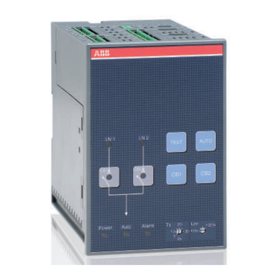
Installation and operating instructions, ATS021 7. Using automatic transfer switch ATS021 7. Using automatic transfer switch ATS021 7.1 Interface Figure 7.1 Interface of ATS021 7.2 Confi guration 7.2.1 Rotary Switches Figure 7.2 Selection of delay time and voltage threshold, the factory settings are shown in the fi gure Ts = Delay time for automatic switching The delay time is the time before activating the switching sequence and the back-switching sequence. -
Page 27: Keypad
Installation and operating instructions, ATS021 7. Using automatic transfer switch ATS021 7.2.2 Keypad Figure 7.3 Keypad on ATS021 RESET key An active alarm can reset by the RESET key. TEST key Setting the automatic transfer switch to test sequence in which it is possible to simulate switching and back-switching sequences step-by-step, by pressing the TEST key. -
Page 28: Leds
Installation and operating instructions, ATS021 7. Using automatic transfer switch ATS021 7.2.3 LEDs Figure 7.4 LEDs on ATS021 LN 1 - CB1 A red LN 1 LED signals the status of the line LN 1 (normal line), when the circuit breaker CB1 is ON. Line status is explained in the table below. -
Page 29: External Transformer
LED is blinking. Power A green Power LED signals the power status. When power is ON, the Power LED is ON. The ATS021 will remain in a standby state at least one minute after power failure. A blinking Power LED indicates standby mode. -
Page 30: Test Sequence
ATS021 is set to the TEST position by pushing the TEST key By pushing the TEST key the automatic transfer switch ATS021 enters the test sequence. All the LEDs are fi rst blinking a couple of times to give the information that the LED is functioning. -
Page 31: Technical Data Of The Automatic Transfer Switch Ats021
Installation and operating instructions, ATS021 8. Technical data 8. Technical data of the automatic transfer switch ATS021 ATS021 Value Operating voltage Main voltage 208Vac - 480 Vac ±20 % Phase voltage 120Vac - 277 Vac ±20 % Rated frequency 50 Hz, 60 Hz ±10 %... -
Page 32: Troubleshooting
Table 9.1 Fault situations in ATS021 9.1 Explanations of internal faults ATS021 When digital Input 1 and 2 are both active, logic is locked and the Alarm LED is ON. When digital Input 3 is active, logic is locked and the Alarm LED is ON. - Page 33 Installation and operating instructions, ATS021 Notes 1SDH000759R0002, L4106...
- Page 34 Installation and operating instructions, ATS021 Notes 1SDH000759R0002, L4106...
- Page 36 БЦ Diamond Center оф.419 (044) 357-74-47 ABB SACE S.p.A The technical data and dimensions are valid at the time of printing. We reserve the right to An ABB Group company subsequent alterations. L.V. Breakers Via Baioni, 35 24123 Bergamo, Italy Telephone +39 035.395.111...