
Related Manuals for ABB ATS021


Summary of Contents for ABB ATS021
- Page 1 Doc. No. 1SDH000759R0002 - L5785 Automatic transfer switch ATS021 Installation and operating instructions...
-
Page 3: Table Of Contents
Times .............................5 Introduction ........................6 Product overview ...........................6 Application scenarios ........................7 Applications of device ATS021 ..................8 Main Line – Emergency Line switching ..................8 Main Line – Emergency generator Switching ................10 Automatic switching without inverse procedure .................11 Line Priority Selection .........................11 Using the automatic transfer switch ................ -
Page 4: Safety Notes
If there are doubts about safe use, the unit must be put out of service. The automatic transfer switch ATS021 must be prevented from operating the circuit breakers before: • accessing the circuit breakers • performing maintenance on circuit breakers or any electrical circuits powered by them •... -
Page 5: Explanation Of Abbreviations And Terms
Installation and operating instructions, ATS021 2. Explanation of abbreviations and terms 2. Explanation of abbreviations and terms 2.1. General information ATS: Automatic Transfer Switch; automatic switching device ATS021: ATS of the ATS02x series, version with rotary switch and LEDs. Circuit Breaker; low voltage automatic Circuit Breaker. -
Page 6: Introduction
ATS021 selects the power supply line by acting directly on the CBs provided on the lines: ATS021 can be used with automatic CBs and ABB SACE switch-disconnectors. -
Page 7: Application Scenarios
Figure 3.1: Diagram showing ATS021 connection to lines LN1-LN2 Application scenarios The ATS021 device may be used in the following applications: • Main line – Emergency line switching • Main line – Emergency generator switching With the Lim rotary switch in the SETUP position, the RESET key can be used to set the following switching logics: •... -
Page 8: Applications Of Device Ats021
Description of time delays 4.1 Main Line – Emergency Line switching Description Both the lines are normally present; in case of a fault in the main line, ATS021 switches on the emergency line used as the reserve line. Figure 4.1:... - Page 9 Installation and operating instructions, ATS021 Applications of device ATS021 Time diagrams Line 1 ok CB1 CLOSED Line 2 ok CB2 CLOSED Figure 4.2: Application time diagram - line-line (main line LN1) 1SDH000759R0002...
-
Page 10: Main Line - Emergency Generator Switching
Applications of device ATS021 4.2 Main Line – Emergency generator Switching Description In case of a mains failure the ATS021 automatically starts up an emergency generator and, as soon as power is available on the generator side, ATS021 starts the automatic switching procedure. -
Page 11: Automatic Switching Without Inverse Procedure
CB1 is opened. ATTENTION If ATS021 is not powered by any of the two lines the device waits for at least one of the two lines (5) to return before proceeding with the switching procedure (6). - Page 12 Installation and operating instructions, ATS021 Applications of device ATS021 Time diagrams Line 1 ok CB1 CLOSED Line 2 ok CB2 CLOSED Figure 4.6: Time Diagram no line priority – generator non in use Line 1 ok CB1 CLOSED Gen start...
-
Page 13: Using The Automatic Transfer Switch
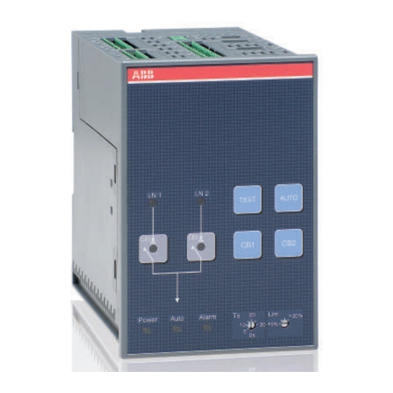
Tbs=300s MAN. AUTO 0s 10 Tbs=Ts SETUP Figure 5.1: Description of ATS021 front panel interface Ref. Description CB1: pushbutton for opening/closing circuit breaker CB1 CB2: pushbutton for opening/closing circuit breaker CB2 RESET: alarms reset button TEST: test mode selection pushbutton... -
Page 14: Led Indicators
LED switches off and the device awaits a line voltage. The moment the normal or the emergency line is restored, with ATS021 in automatic, the unit analyses the conditions of the lines monitored and the status of the circuit breakers and proceeds with the switching operation in accordance with the situation concerned. -
Page 15: Keypad Keys
In case of alarm, press RESET to reset the alarm. TEST button ATS021 must be in the manual position. Press the TEST key, see Figure 5.1/4, to set the test mode of the direct and inverse switching sequences. To exit the TEST mode press RESET. -
Page 16: Rotary Selectors
Description of Lim rotary selector Manual mode ATS021 can be set in manual mode by turning the Lim rotary switch, see Figure 5.1/13 on the front panel in the MAN section. For example, when the Lim rotary switch is in the MAN area in position 20, ATS021 operates in Manual mode and the voltage threshold is ±20 %;... - Page 17 1. turn the Lim rotary switch to the SETUP position 2. press the RESET button to select the switching logic used by ATS021. 3. the selection of a definite operating logic is indicated by a different lighting up of the LEDs according...
-
Page 18: Selector For Setting Delay Times Ts And Tbs
Description of ATS021 delay time Two different sections are available: • section Tbs=Ts: select time Ts by turning the rotary switch to one of the possible positions. ATS021 uses a time Tbs equal to time Ts selected. The possible selections are 0s, 10s, 20s, 30s. -
Page 19: Dip Switches
Figure 5.4: ATS021 lower interface The parameters which can be modified by means of the dip switches in the lower part of the ATS021 are: Rated voltage: can be set by means of DIP switches S23-1...3 Rated frequency: can be set by means of DIP switch S23-4... - Page 20 DIP switch S23-4...3 for setting rated frequency of lines monitored S23-4 Positions Rated frequency fn 50Hz (default) 60Hz Figure 5.6: Description of settings DIP Switches S23 - ATS021 DIP switches S24 DIP switch S24-1 for setting neutral S24-1 Positions Neutral N used (default)
-
Page 21: Using Pushbuttons In Manual Mode
Tgoff = Ts Tgoff = 5 minutes Figure 5.7: Description of settings DIP Switches S22 - ATS021 5.6 Using pushbuttons in manual mode Opening/Closing circuit breakers CB1, CB2 In manual mode the circuit breakers can be controlled by means of pushbuttons CB1 and CB2. In case of a fault, the alarms are activated by the same methods as those for the automatic switching sequence. -
Page 22: Test Modes
With ATS021 in manual mode, keep TEST pressed for at least 3 seconds: when the TEST button is released, all the LEDs flash simultaneously twice and then the Auto LED flashes for 0.5 sec every 2 sec . -
Page 23: Input And Output Signals
- Normal operation= contact open DO7 Manual mode signalling Contact DO7 provides the indication of the operating mode of the ATS021 unit (X25:2 - contact closed if the unit is in manual mode and open if in automatic mode) DO8 Logic enabled indication Contact DO8 provides the indication of the operating mode of the ATS021 unit (X25:3 –... -
Page 24: Input Signals
DI3 Switching Logic Activation/Deactivation Input DI3 is used for enabling/disabling the switching logic. The function may be used for integrating generic alarms coming from the plant the presence of which leads to disabling of ATS021 automatic switching logic. • DI3 open: logic disabled •... - Page 25 X31:2 CB1 status input Open = CB open; Closed = CB closed X31:3 CB2 status input Open = CB open; Closed = CB closed X31:4 Earth connection Table 6.1: Description of function and type of connectors ATS021 1SDH000759R0002...
-
Page 26: Technical Data
NOTES 1. In the three-phase system without neutral, an external voltage transformer must be used. The features of the external transformer for power supply only of the ATS021 are: - transformer from connected voltage to phase voltage - Isolation transformer - size 40VA. -
Page 27: Installation Of Device Ats021
Installation and operating instructions, ATS021 8. Installation of device ATS021 The automatic transfer switch ATS021 must be mounted on the panel front door or on DIN rail. 8.1. Door-mounted Automatic Transfer Switch ATS021 The Automatic Transfer Switch ATS021 can be mounted on the door as shown in Figure 8.1. -
Page 28: Din Rail-Mounted Automatic Transfer Switch Ats021
Installation and operating instructions, ATS021 Installation of device ATS021 8.2. DIN rail-mounted Automatic Transfer Switch ATS021 The automatic transfer switch ATS021 can be mounted on a 35mm DIN rail as shown in Figure 8.2. 35mm EN 50022 Remove Figure 8.2:... -
Page 29: Regulatory Standards
Regulatory standards Installation and operating instructions, ATS021 9. Regulatory standards ATS021 conforms to the following regulatory standards: • European Directive 73/23 “LVD – Low Voltage Directive” • EN 50178 electronic equipment for use in power Installations • EN-IEC 62103 electronic equipment for use in power Installations •... -
Page 30: Troubleshooting
Installation and operating instructions, ATS021 10. Problem solving 10. Troubleshooting The alarms are indicated by a flashing Alarm LED on the front of the ATS021. The list of possible meanings are shown in the Table below: Alarm Fault Action Opening 1 Alarm... - Page 31 Installation and operating instructions, ATS021 1SDH000759R0002...
- Page 32 Due to possible development of Standards as well as of materials, the characteristics and dimensions specified in this Installation and operating instructions may be considered as binding only after confirmation by ABB SACE Division. © Copyright 2011 ABB. All rights reserved.