Table of Contents
Advertisement
Quick Links
Advertisement
Table of Contents

Related Manuals for ABB UC series


Summary of Contents for ABB UC series
- Page 1 1ZSE 5492-124 en, Rev. 6 On-load tap-changer, type UCG Maintenance guide...
- Page 2 Any specific application not covered should be referred directly to ABB, or its authorized representative. ABB makes no warranty or representation and assumes no liability for the accuracy of the information in this document or for the use of such information. All information in this document is subject to change without notice.
- Page 3 To avoid damaging the unit, never exceed the operating limits WARNING stated in delivery documents and on rating plates. Do not alter or modify a unit without first consulting ABB. Before any work is carried out on the tap-changer: Make sure that the transformer is disconnected and Follow local and international wiring regulations at all times.
- Page 4 During service During oil handling WARNING WARNING Small amounts of explosive gases may be emitted Unused transformer oil is harmful. Fumes from from the breathing devices (dehydrating breather or unused warm oil may irritate the respiratory organs one-way breather). Make sure that no open fires, hot and the eyes.
- Page 5 WARNING After oil filling There is always a cushion of explosive gases in the CAUTION top of the diverter switch housing. No open fire, hot surfaces or sparks may be present during opening of the housing or draining from the valve. After the Do not energize the transformer earlier than three cover is removed let the gas vent away approximately hours after oil filling at atmospheric pressure.
-
Page 6: Table Of Contents
Content 1. Introduction ..........................9 1.1 General .........................9 1.2 Maintenance schedule ....................10 1.2.1 Inspection .......................10 1.2.2 Overhaul .........................10 1.2.3 Contact replacement ....................12 1.3 Tightening torque ......................12 2. Inspection ..........................13 3. Overhaul ..........................14 3.1 Required tools and materials ..................14 3.2 Procedure ........................14 3.3 Preparations .........................14 3.3.1 On-load tap-changer position .................14 3.3.2 Disconnection and earthing of the transformer ............15... - Page 7 4. Contact replacement ......................27 4.1 Dismantling the boards ....................29 4.2 Dismantling the moving main contacts ................29 4.3 Dismantling the moving transition contacts ..............31 4.4 Mounting the moving transition contacts ...............32 4.5 Mounting the moving main contacts ................33 4.6 Replacing the fixed main contacts .................34 4.7 Replacing the fixed transition contacts ................34 4.8 Mounting the boards with transition resistors and fixed contacts ........34 5.
-
Page 9: Introduction
1. Introduction 1.1 General The UC range of on-load tap-changers manufactured by ABB has been developed over many years to provide maximum reliability. The simple and rugged design gives a service life equal to the service life of the transformer. Minimum maintenance is required for trouble-free operation. -
Page 10: Maintenance Schedule
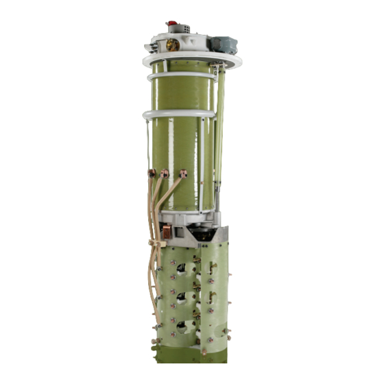
– Fixed main contacts If the on-load tap-changer is equipped with an oil filter unit – Moving main contacts from ABB, it should be inspected once a year according to – Fixed transition contacts the oil filter unit manual. – Moving transition contacts –... - Page 11 Cover Diverter switch housing Oil valve Pressure relay Bevel gear Position indicator Top-section Serial No. Shielding-ring Earthing terminal Draining tube Connection flange for gas operated relay Insulating cylinder Insulating shaft Diverter switch Shielding-ring Shielding-ring Plug-in contacts Transition resistors Fixed and moving contacts Bottom section Serial No.
-
Page 12: Contact Replacement
1.2.3 Contact replacement On the rating plate of the on-load tap-changer the estimated contact life of the breaking contacts in the diverter switch at rated load is stated. The contacts will withstand a very large number of switching operations. For normal power transformers the number of operations of the diverter switch is approximately 20 per day, which means that replacement of the contacts is not normally necessary during the life of the transformer. -
Page 13: Inspection
2. Inspection The inspection mainly consists of a visual check of the motor- drive mechanism and the conservator once a year while the transformer is in service. In the motor-drive mechanism the following points are to be checked: – Motor and counter –... -
Page 14: Overhaul
3. Overhaul WARNING When measuring contact timing, add this equipment: – See section 3.18 Before any work is carried out on the on-load tap-changer: Make sure that the transformer is When replacing contacts (chapter 4), add this equipment: disconnected and that earthing is properly carried –... -
Page 15: Disconnection And Earthing Of The Transformer
50 litres, should be kept ready to replace waste oil If the on-load tap-changer is equipped with an oil and for cleaning. filter unit for continuous oil filtration from ABB and it is maintained and operated according to our instructions, oil draining and filtering is not needed,... -
Page 16: Lifting And Cleaning The Diverter Switch
If the on-load tap-changer is equipped with an oil housing is pumped out, conducting tubes and hoses filter unit for continuous oil filtration from ABB and that are earthed should be used to avoid the risk of it is maintained and operated according to our... -
Page 17: Cleaning
If the on-load tap-changer is equipped with an oil switch housing should be carried out by using filter unit for continuous oil filtration from ABB and brushes and rags and by flushing with oil. it is maintained and operated according to our instructions, no further oil filtration is necessary. -
Page 18: Checking The Contact Positions
3.9 Checking the contact positions Operate the diverter switch back to the first side and check Those parts of the fixed contacts and the moving contacts the clearance again. If still too small, put in a shim more and which are exposed to arcing during an operation are tipped by test again. - Page 19 0.5–2 mm Fixed main switching contact Moving main switching contact Ø6.4 Copper part Thickness 1 mm Current bar Moving main Fixed main contact contact Board Fig. 5. Fixed and moving contacts clearance. Fig. 6. Transition contacts. 1ZSE 5492-124 en, Rev. 6 | Maintenance guide UCG 19...
-
Page 20: Checking The Contact Wear
3.10 Checking the contact wear 3.11 Checking the transition resistors The contact system consists of fixed and moving contacts. Measurement is carried out on the side with open contacts. Connect one cable from the ohmmeter to a fixed main contact Check the degree of contact burning on the breaking and the other cable to a fixed transition contact. -
Page 21: Checking And Replacing Supervisory Equipment
When the diverter switch is lowered, check visually that its 3.14 Checking and replacing supervisory equipment plug-in contacts are aligned with the contacts in the cylinder Accessories and safety devices that are not standard, but wall. might be mounted at delivery, are described in instruction 1ZSC000562-AAD. -
Page 22: Lubrication Of The On-Load Tap-Changer And The Drive Shaft System
3.15 Lubrication of the on-load tap-changer and the drive The connection to the oil conservator is designed to shaft system automatically give a gas cushion when filling at atmospheric The bevel gears are greased at delivery and the same type of pressure. -
Page 23: Restoring The Gas Cushion
6. Close the oil valve and disconnect the pump. continuous oil filtration from ABB, and it is installed according 7. Connect the output side of the pump to the oil valve. -
Page 24: Waiting Period
Connect the lamps as shown in Fig. 11. If the result is beyond the limits given here, please contact ABB. The diverter switch contacts are designated as shown in Fig. 12. Determine if x or v contacts are closed. In the... - Page 25 Fig. 11. Indicator lamp connection during contact timing test. v-contacts x-contacts Fig. 12. The diverter switch outlet marking. 1ZSE 5492-124 en, Rev. 6 | Maintenance guide UCG 25...
- Page 26 Position Min. 3 turns Position Min. 3 turns Position –—— Contact closed Turns of the hand crank of the mechanism Fig. 13. Example of contact-timing diagram, BUE. Position Min. 2 turns Position Min. 2 turns Position –—— Contact Turns of the hand crank of the mechanism Fig.
-
Page 27: Contact Replacement
4. Contact replacement CAUTION ABB recommends that only authorized personnel from ABB carry out contact replacement. Replace worn-out main switching contacts and transition contacts as required. (It is not necessary to replace both main switching contacts and transition contacts if, for instance, only the main switching contacts are worn out). - Page 28 Fixed main switching contact Conical spring- washer Plain Fixed transition washer contact Locking washer (mounted vertically on some types) Plain washer Conical spring Guide pin washer Conical spring washer Connection for transition resistor Plain washer Moving transition contact Fixed transition contact Moving main switching contact...
-
Page 29: Dismantling The Boards
4.1 Dismantling the boards 4.2 Dismantling the moving main contacts Dismantle the boards from the frame by removing the six Dismantle the moving main contacts according to Figs. 18 screws and the locking washers from each board (Fig. 16). and 19. Take away split pins, washers and springs in both ends of shafts 1–3. - Page 30 Contact Washer with larger diameter Shaft 1 Shaft 2 Shaft 3 Fig. 18. Contact replacement, taking away split pins. Contact Shaft 1 Fig. 19. Contact replacement, pulling out shaft. 30 Maintenance guide UCG | 1ZSE 5492-124 en, Rev 6...
-
Page 31: Dismantling The Moving Transition Contacts
4.3 Dismantling the moving transition contacts Dismantling of the moving transition contacts should be carried out according to Figs. 20 and 21. The transition contacts are held by a common shaft 4 going through all the contacts. The shaft 4 is locked with two split pins (Fig. 21). Remove Shaft 4 the split pins and punch out the shaft with a 5 mm mandrel of brass and take care of the springs, washers and contacts... -
Page 32: Mounting The Moving Transition Contacts
4.4 Mounting the moving transition contacts Proceed with the other side of the diverter switch. Put a ruler Mount the moving transition contacts according to Fig. 21. on the linings of the tran-sition contacts. No lining should lie more than 1 mm from the ruler. A replacement contact consists of a contact with mounted spring. -
Page 33: Mounting The Moving Main Contacts
4.5 Mounting the moving main contacts Proceed with the outer phases. Put the outermost silver Fig. 22 shows how to mount the moving main contacts, washer and contact on the shaft and punch the shaft into and how to place washers and springs. The contacts are the bearing hole. -
Page 34: Replacing The Fixed Main Contacts
4.6 Replacing the fixed main contacts Check that the linings of the fixed main contacts are aligned Unscrew the fixed main contacts, see Fig. 15. Mount new with the linings of the moving main contacts. If not, loosen contacts. Use new conical spring washers and locking nuts. the nuts slightly and adjust the fixed main contacts. -
Page 35: Specification Of Materials
5. Specification of materials 5.1 General 5.5 Conductors On disposal of this product, it is recommended that local environmental regulations in each country are met. For Material Approx. amount environmental reasons, materials used are specified. Copper 5–10 kg Cellulose 5.2 Diverter switch housing 5.6 Gearing mechanism Material Approx. - Page 36 Contact us ABB AB Components SE-771 80 Ludvika, Sweden Phone: +46 240 78 20 00 Fax: +46 240 121 57 E-Mail: sales@se.abb.com www.abb.com/electricalcomponents...