Vulcan-Hart C24GA6, C24GA10, ML-136021, ML-136022 Service Manual
Vulcan-hart convection steamers service manual c24ga6 ml-136021, c24ga10 ml-136022
Hide thumbs
Also See for C24GA6, C24GA10, ML-136021, ML-136022:
- Installation & operation manual (44 pages) ,
- Service manual (40 pages) ,
- Brochure (8 pages)
Table of Contents
Advertisement
This manual is prepared for the use of trained Vulcan Service
Technicians and should not be used by those not properly
qualified. If you have attended a Vulcan Service School for this
product, you may be qualified to perform all the procedures
described in this manual.
This manual is not intended to be all encompassing. If you have
not attended a Vulcan Service School for this product, you should
read, in its entirety, the repair procedure you wish to perform to
determine if you have the necessary tools, instruments and skills
required to perform the procedure. Procedures for which you do
not have the necessary tools, instruments and skills should be
performed by a trained Vulcan Service Technician.
Reproduction or other use of this Manual, without the express
written consent of Vulcan, is prohibited.
For additional information on Vulcan-Hart or to locate an authorized parts and
service provider in your area, visit our website at www.vulcanhart.com
VULCAN-HART
DIVISION OF ITW FOOD EQUIPMENT GROUP, LLC
WWW.VULCANHART.COM
SERVICE MANUAL
C24GA SERIES
CONVECTION
STEAMERS
C24GA6
C24GA10
- NOTICE -
MODELS
ML-136021
ML-136022
3600 NORTH POINT BLVD.
BALTIMORE, MD 21222
F35425 (February 2006)
Advertisement
Table of Contents
Troubleshooting

Related Manuals for Vulcan-Hart C24GA6, C24GA10, ML-136021, ML-136022


Summary of Contents for Vulcan-Hart C24GA6, C24GA10, ML-136021, ML-136022
- Page 1 Vulcan Service Technician. Reproduction or other use of this Manual, without the express written consent of Vulcan, is prohibited. For additional information on Vulcan-Hart or to locate an authorized parts and service provider in your area, visit our website at www.vulcanhart.com VULCAN-HART DIVISION OF ITW FOOD EQUIPMENT GROUP, LLC WWW.VULCANHART.COM...
-
Page 2: Table Of Contents
TABLE OF CONTENTS GENERAL... 4 Introduction ... 4 Installation ... 4 Operation ... 4 Cleaning ... 4 Specifications ... 4 Gas Line Pressures ... 4 Burner Pressure ... 4 Electrical ... 4 Water Supply ... 4 Tools ... 4 Standard ... 4 Special ... - Page 3 ELECTRICAL OPERATION ... 22 Water Level Controls ... 22 Low Level Cut-Off & Differential Control ... 22 Sequence of Operation ... 22 Initial Fill and Preheat Conditions ... 22 Schematics ... 25 Component Location Cabinet Base Generator ... 28 Component Function Cabinet Base Generator ... 29 Component Location Cooking Compartment ...
-
Page 4: General
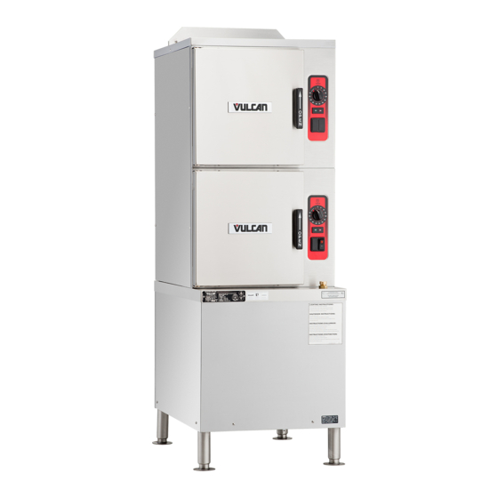
C24GA SERIES CONVECTION STEAMERS - GENERAL INTRODUCTION Procedures in this manual will apply to all models unless specified. Pictures and illustrations can be of any model unless the picture or illustration needs to be model specific. INSTALLATION Refer to the Installation and Operation Manual for detailed installation instructions on steamers. -
Page 5: Removal And Replacement Of Parts
C24GA SERIES CONVECTION STEAMERS - REMOVAL AND REPLACEMENT OF PARTS REMOVAL AND REPLACEMENT OF PARTS COVERS AND PANELS WARNING: DISCONNECT THE ELECTRICAL POWER TO THE MACHINE AND FOLLOW LOCKOUT / TAGOUT PROCEDURES. Cooking Compartment Right Side Panel Remove the screws then remove the right side panel from the compartment. -
Page 6: Cabinet Base Left Side Panel
C24GA SERIES CONVECTION STEAMERS - REMOVAL AND REPLACEMENT OF PARTS Cabinet Base Left Side Panel Remove the screws then remove the left side panel from the cabinet base. Cabinet Base Front Panel Remove the screws then remove the front panel from the cabinet base. -
Page 7: Door Gasket
C24GA SERIES CONVECTION STEAMERS - REMOVAL AND REPLACEMENT OF PARTS Door Gasket Open the door. Remove screws from the gasket guard and gasket plate. Remove the gasket guard and the gasket plate. Position the new gasket on the gasket plate. Reverse the procedure to install. -
Page 8: Door Latch Assembly
C24GA SERIES CONVECTION STEAMERS - REMOVAL AND REPLACEMENT OF PARTS Door Latch Assembly Open the door. Remove screws from the top and bottom of the door. Pull the outer door panel out from the door housing. Remove the pins and retaining rings. Remove the latch assembly from the door. -
Page 9: Main Burner
C24GA SERIES CONVECTION STEAMERS - REMOVAL AND REPLACEMENT OF PARTS MAIN BURNER WARNING: DISCONNECT THE ELECTRICAL POWER TO THE MACHINE AND FOLLOW LOCKOUT / TAGOUT PROCEDURES. Remove front and side covers as outlined under COVERS AND PANELS. Disconnect the gas line at gas combination control valve. - Page 10 C24GA SERIES CONVECTION STEAMERS - REMOVAL AND REPLACEMENT OF PARTS Drain the generator and allow steamer to cool, if necessary. Remove rear and side panels as outlined under COVERS AND PANELS. Disconnect gas line at gas combination control valve. F35425 (February 2006) Disconnect wires to burner assembly.
-
Page 11: Fill And Cold Water Solenoid Valves
C24GA SERIES CONVECTION STEAMERS - REMOVAL AND REPLACEMENT OF PARTS 16. Rotate pressure relief valve coupling to allow pressure relief valve to be rotated about 90° so that valve is below generator top level. 17. Remove pressure switch from generator. 18. -
Page 12: Pilot Spark/Probe Flame Sensor
C24GA SERIES CONVECTION STEAMERS - REMOVAL AND REPLACEMENT OF PARTS Disconnect the water lines for the solenoid valve being serviced and remove the solenoid valve from the unit. Reverse procedure to install solenoid valve. PILOT/SPARK PROBE FLAME SENSOR Remove main burner assembly as outlined under MAIN BURNER in REMOVAL AND REPLACEMENT OF PARTS. -
Page 13: Service Procedures And Adjustments
C24GA SERIES CONVECTION STEAMERS - SERVICE PROCEDURES AND ADJUSTMENTS SERVICE PROCEDURES AND ADJUSTMENTS WARNING: CERTAIN PROCEDURES IN THIS SECTION REQUIRE ELECTRICAL TEST OR MEASURE- MENTS WHILE POWER IS APPLIED TO THE MACHINE. EXERCISE EXTREME CAUTION AT ALL TIMES. IF TEST POINTS ARE NOT EASILY ACCESSIBLE, DISCONNECT POWER AND FOLLOW LOCKOUT / TAGOUT PROCEDURES, ATTACH TEST EQUIPMENT AND REAPPLY POWER TO TEST. -
Page 14: Pilot Burner Adjustment
C24GA SERIES CONVECTION STEAMERS - SERVICE PROCEDURES AND ADJUSTMENTS The screw head should not extend out past the screw housing. If gas valve energizes, proceed to step 5. If gas valve does not energize, check the following: Remove the lead wires from the switch and verify with a meter that the switch contacts are closing with the blower on. -
Page 15: Operating Pressure Switch
C24GA SERIES CONVECTION STEAMERS - SERVICE PROCEDURES AND ADJUSTMENTS 16. Turn off the machine. 17. Re-install pilot, reconnect wire # 35. 18. Turn on the machine, let generator fill 19. Observe proper functioning of gas burner. Operating Pressure Switch Remove the cabinet base front panel as outlined under COVERS AND PANELS. -
Page 16: Thumb Wheel Adjustment
C24GA SERIES CONVECTION STEAMERS - SERVICE PROCEDURES AND ADJUSTMENTS Thumb Wheel Adjustment The thumb wheel directly below the microswitch changes both the cut-out (off) and the cut-in (on) points of the operating Pressure Switch. Turn the thumb wheel to obtain the proper cut-out (off) setting. -
Page 17: Automatic Ignition Systems
C24GA SERIES CONVECTION STEAMERS - SERVICE PROCEDURES AND ADJUSTMENTS AUTOMATIC IGNITION SYSTEMS When the main power switch is turned on and the water level is above LLCO, the ignition control module is energized with 24 volts between terminals five and six. -
Page 18: Ignition Test
C24GA SERIES CONVECTION STEAMERS - SERVICE PROCEDURES AND ADJUSTMENTS If 24VAC is present, then replace ignition control module and retest. It may take up to 3 seconds for the module to reset if main power is turned off then back on. If 24VAC is not present, then ensure that transformer is receiving 120VAC input. -
Page 19: Cooking Compartment
C24GA SERIES CONVECTION STEAMERS - SERVICE PROCEDURES AND ADJUSTMENTS Verify burner air pressure is 0.35" to 0.4" W.C. Turn the gas combination control valve on and wait until main burner lights. Observe the manometer pressure reading and compare to the pressure chart below. GAS PRESSURE READINGS (INCHES W.C.) MANIFOLD LINE*... -
Page 20: Striker Adjustment
C24GA SERIES CONVECTION STEAMERS - SERVICE PROCEDURES AND ADJUSTMENTS Striker Adjustment Reinstall the striker with the slot pointing upwards and hand tighten nut only. Close the door to center the striker in the oval mounting hole. Open the door and check the striker’s slot for horizontal alignment. -
Page 21: Cooking Cycle Test
C24GA SERIES CONVECTION STEAMERS - SERVICE PROCEDURES AND ADJUSTMENTS 10. After 40 minutes, turn power switch off and allow steam generator to completely drain, 5 minutes. 11. Rinse steam generator with clean water: Turn power switch on. When ready light comes on, turn cooking timers on for 30 seconds to rinse the steam tubes and nozzles. -
Page 22: Electrical Operation
C24GA SERIES CONVECTION STEAMERS - ELECTRICAL OPERATION ELECTRICAL OPERATION WATER LEVEL CONTROLS Low Level Cut-Off and Differential Control The steamer is equipped with three water level sensing probes (high, low and low level cut-off) and a single water level control board. The water level control board performs two functions: Provide low level cut-off protection to shut off the heat source in case the water level drops below... - Page 23 C24GA SERIES CONVECTION STEAMERS - ELECTRICAL OPERATION Turn power switch on. Timer de-energized. Operating voltage applied to control compartment after cavity relay is latched on. Water level control (WLC) energized. Low level (LL) relay N.C. contacts provide operating voltage to fast-fill solenoid.
- Page 24 C24GA SERIES CONVECTION STEAMERS - ELECTRICAL OPERATION Compartment control (Units after Dec. 1, 2005) Refer to schematic diagrams 00855693 & 00856656. Compartment door closed causing door switch to close and Ready Light to illuminate. 120 VAC applied through door switch to timer contact 11 and 21.
-
Page 25: Schematics
C24GA SERIES CONVECTION STEAMERS - ELECTRICAL OPERATION SCHEMATIC DIAGRAMS Generator Schematic Diagram Page 25 of 40 F35425 (February 2006) - Page 26 C24GA SERIES CONVECTION STEAMERS - ELECTRICAL OPERATION Schematic Diagram - Compartment Controls (Standard) F35425 (February 2006) Page 26 of 40...
- Page 27 C24GA SERIES CONVECTION STEAMERS - ELECTRICAL OPERATION Schematic Diagram - Compartment Controls (Constant Steam) Page 27 of 40 F35425 (February 2006)
-
Page 28: Component Location Cabinet Base Generator
C24GA SERIES CONVECTION STEAMERS - ELECTRICAL OPERATION COMPONENT LOCATION CABINET BASE GENERATOR F35425 (February 2006) Page 28 of 40... -
Page 29: Component Function Cabinet Base Generator
C24GA SERIES CONVECTION STEAMERS - ELECTRICAL OPERATION COMPONENT FUNCTION CABINET BASE GENERATOR Water Level Control and Level Sensing Probes... The Water Level Control circuit board and Level Sensing Probe Assembly Generator Fast Fill Solenoid Valve... The Generator Fast Fill Solenoid Valve is located on the right side of the Generator Slow Fill Solenoid Valve... - Page 30 C24GA SERIES CONVECTION STEAMERS - ELECTRICAL OPERATION Hold Thermostat... The Hold Thermostat energizes the Generator Slow Fill Solenoid Valve when Drain... The Drain is located on the lower right of the base and removes steam conden- Metal Fiber Main Burner... The Metal Fiber Main Burner is accessible from the front. This burner heats the Gas Combination Control Valve...
-
Page 31: Component Location Cooking Compartment
C24GA SERIES CONVECTION STEAMERS - ELECTRICAL OPERATION COMPONENT LOCATION COOKING COMPARTMENT Page 31 of 40 F35425 (February 2006) -
Page 32: Component Function Cooking Compartment
C24GA SERIES CONVECTION STEAMERS - ELECTRICAL OPERATION COMPONENT FUNCTION COOKING COMPARTMENT General The upper section of the steamer consists of two separate cooking compartments. Each compartment functions independently with its own set of controls. Power is supplied to the controls only after the steam pressure rises above 4 psi to energize the compartment latching relay. -
Page 33: Troubleshooting
C24GA SERIES CONVECTION STEAMERS - TROUBLESHOOTING TROUBLESHOOTING General The following paragraphs provide descriptive information of the most common troubles that can occur in the steamer. The Troubleshooting Chart provides a list of other typical fault conditions. The left-hand column of the table lists typical symptoms and the right-hand column lists probable causes and the suggested remedies. -
Page 34: Troubleshooting Sequence Of Operation
C24GA SERIES CONVECTION STEAMERS - TROUBLESHOOTING TROUBLESHOOTING SEQUENCE OF OPERATION STEP FUNCTION Power On Fill Stage 1 Low Level Probe Confirmation Burner Operation Blower Blower Pressure Switch Pilot Ignition Flame Sense Main Burner Generator Initial Heat Up Fill Stage 2 Generator Full Ready Full Pressure... -
Page 35: Troubleshooting Chart
C24GA SERIES CONVECTION STEAMERS - TROUBLESHOOTING TROUBLESHOOTING CHART SYMPTOM Compartment leaks steam or water around door. Cold water condenser not operating properly. Steam visible inside compartment when unit is not in cook mode. Heat coming on without water in. Pressure relief valve opening or leaking. Generator will not heat or build pressure. - Page 36 C24GA SERIES CONVECTION STEAMERS - TROUBLESHOOTING SYMPTOM Generator does not fill. Timer motor does not run. Door not closing properly. Door won’t open or hard to open. Buzzer not operating. Burner won’t light or won’t stay lit. Pilot not lit or goes out. F35425 (February 2006) POSSIBLE CAUSES Water supply not on.
- Page 37 C24GA SERIES CONVECTION STEAMERS - TROUBLESHOOTING SYMPTOM Spark igniter not sparking. POSSIBLE CAUSES Incorrect spark gap setting. Poor ground between pilot bracket and burner. Loose, broken or damaged lead wires (including ground) from ignition module to ignitor. Ignitor boot on ignition cable loose, damaged or missing causing excessive ignition voltage leakage.
-
Page 38: Condensed Spare Parts List
C24GA SERIES CONVECTION STEAMERS - CONDENSED SPARE PARTS LIST CONDENSED SPARE PARTS LIST C24GA SERIES CONVECTION STEAMERS PART NO. 419315 POWER CORD 419359 CABLE, IGNITOR, HIGH VOLTAGE 842049 DOOR SWITCH 411500-12 TRANSFORMER 120V/24V 411690-1 TIMER COMPARTMENT 416535-4 SWITCH RELAY 416535-6 RELAY CAVITY COLD WATER CONDENSATE 423813-3 CABLE, FLAME SENSE... - Page 39 Page 39 of 40 F35425 (February 2006)