Table of Contents
Advertisement
Quick Links
These models are RoHS-compliant. Provide
servicing referring to "NOTES FOR SERVICING
RoHS-COMPLIANT PRODUCTS" described in
the service manual.
CAUTION
Before servicing this chassis, it is important that the service person reads the "PRODUCT SAFETY NOTICE" in this service
manual.
•
Rated power supply : 100-240 V AC, 50/60 Hz
•
Rated input
: 2.9A
•
Display technology : 0.55 inch Single DLP panel
•
Pixels
: 800x600= 480,000 pixels (SD206U)
1,024x768= 786,432 pixels
(XD206U/XD206U-G)
•
Colors
: 16,770,000 colors
•
Projection lens
: F2.5(Wide), f=19.9-21.4 mm (SD206U)
•
F2.4(Wide), f=19-21.9 mm
(XD206U/XD206U-G)
•
Light source lamp :205 W
•
Picture Size
: 40-300 inch (wide), aspect ratio rate 4:3
•
PC compatibility : 640 x 400 (Expand) -800 x 600 (Real) -
1,024 x 768 (Compress) (SD206U)
640 x 400 (Expand) -1,024 x 768 (Real) -
1,280 x 1,0224 (Compress)
(XD206U/XD206U-G)
Sync on Green available
•
Video compatibility : NTSC / NTSC 4.43 / PAL (including PAL-M, N)
/ SECAM / PAL-60 / Component Video
(DVD/HDTV) (480i/p, 576i/p, 720p, 1080i)
Copyright © 2007 Mitsubishi Electric Corporation All Rights Reserved.
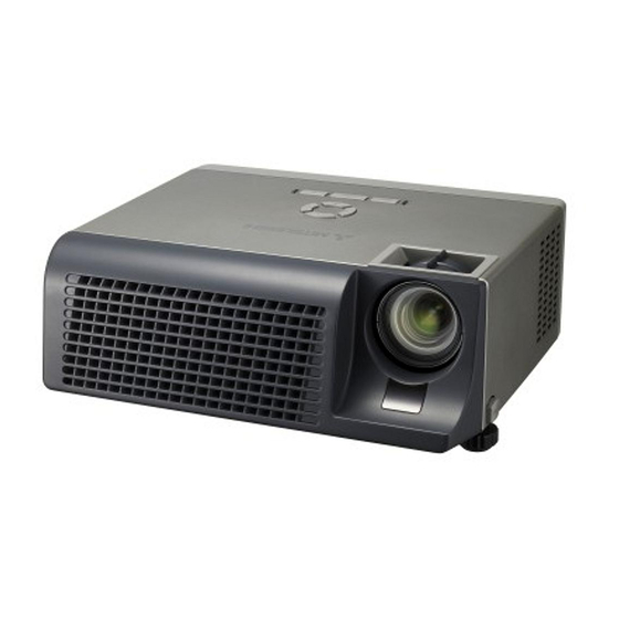
DLP™ PROJECTOR
SPECIFICATIONS
•
Speaker
•
S-Video input
•
Chroma signal
•
Video input
•
Audio input
•
Analog RGB input : RGB: 0.7 Vp-p 75Ω(negative sync)
•
Control connector : Serial terminal(RS-232C) (D-SUB 9 pin)
•
Outside dimensions : 256 x 102 x 223mm (width x height x depth)
•
Weight
•
Temperature, humidity : +41°F (+5°C) - +95°F (+35°C), 30-90%
(performance guaranteed)
• Weight and dimensions shown are approximate.
• Design and specifi cations are subject to change without notice.
Pb Solder, Pb Joints, Pb PCA
This product uses lead-free solder
on the circuit boards. For repairing
circuit boards, see "Precautions for
resoldering" in this Service Manual.
MODEL
SD206U / XD206U /
XD206U-G
: 2W Mono, Round type ø2.5cm x 1
: Luminance signal: 1.0 Vp-p
75Ω (negative sync)
: 0.286 Vp-p 75Ω (burst signal)
: 1.0 Vp-P 75Ω(negative sync)
: 350 mVrms, 10 kΩ or more
YPbPr/YCbCr: Y-> 1.0 Vp-p (negative sync)
PbPr/CbCr-> 0.7 Vp-p
HD/CS: TTL level(positive or negative)
VD: TTL level(positive or negative)
USB terminal(for Page Up/Down)
: Approx. 2.9kg
2007
Advertisement
Table of Contents

Related Manuals for Mitsubishi Electric SD206U


Summary of Contents for Mitsubishi Electric SD206U
- Page 1 Video compatibility : NTSC / NTSC 4.43 / PAL (including PAL-M, N) / SECAM / PAL-60 / Component Video • Weight and dimensions shown are approximate. (DVD/HDTV) (480i/p, 576i/p, 720p, 1080i) • Design and specifi cations are subject to change without notice. Copyright © 2007 Mitsubishi Electric Corporation All Rights Reserved.
-
Page 2: Notes For Servicing Rohs-Compliant Products
NOTES FOR SERVICING RoHS-COMPLIANT PRODUCTS Follow the notes and instructions below when servicing RoHS-compliant products. 1. For RoHS-compliant products, be sure to use RoHS-compliant service parts. 2. Check the presence of <G> marking on the rating plate to distinguish RoHS- compliant product from non-RoHS-compliant product. -
Page 3: Table Of Contents
CONTENTS – FILE “COVERPGE” – SPECIFICATIONS ..............................NOTES FOR SERVICING RoHS-COMPLIANT PRODUCTS ................CONTENTS ................................– FILE “EXPOSED” – TRADE MARK, REGISTERED TRADEMARK ...................... PRODUCT SAFETY NOTICE ..........................SAFETY PRECAUTIONS ............................PRECAUTIONS FOR RESOLDERING ......................... EXPOSED VIEW ..............................DLP ASSY ................................ Sub ASSY ................................ - Page 4 TROUBLESHOOTING Power source 1 No Power Source Fan failure after after turning on turning on Replace AC Check AC socket Check fan Reconnect fan and connector socket connection Replace AC Check AC Replace fan Check fan power cable power cable Replace MAIN Check MAIN Replace Fuse...
- Page 5 Power source 2 Fail to light up No Volume Refer to LED Replace keypad Check LED Check keypad and indicator and follow and keypad FPC indication keypad FPC cable indicative actions cable Check Check Replace lamp Replace speaker lamp life speaker Replace POWER Replace MAIN...
- Page 6 Video signal 1 Computer Video No Signal No Signal Turn on Turn on Check Check source source source source Check Replace cable Replace cable Check cable cable Replace MAIN Replace optical Check monitor Check PCB ASSY unit out signal optical unit Check Replace optical unit...
- Page 7 Video signal 2 Image abnormal Color abnormal Adjust Power on again Check input cable input signal and reset OSD and signal setting Check color Adjust color Adjust Check input cable wheel wheel input signal and signal setting Replace MAIN Replace MAIN Check MAIN Check MAIN PCB ASSY...
- Page 8 Operation function Remote control failure Button failure Replace keypad Check keypad and Check battery level Replace battery and keypad FPC keypad FPC cable cable Check MAIN Replace MAIN Replace remote Check remote control PCB ASSY PCB ASSY control Replace remote Check remote control sensor control sensor...
- Page 9 DIAGNOSIS INFORMATION Outline of self-diagnosis function This projector is provided with the self-diagnosis function. In case of any failure, the LED at the top of the projector will indicate the failure. Diagnosis result indication LED indication and failures are described in the following table. LED can be reset “automatically” or “by turning on/off of the main power”...
- Page 10 • The projector’s maximum resolution is 1024 x 768 pixels (800 signal, the signal mode is indicated as TV60 or TV50. When x 600 pixels for SD206U). they are supplied to the COMPONENT terminal, the signal It may not display images of higher resolutions than 1024 x mode is indicated as 480I or 576I.
- Page 11 H Timing V Timing HDISP VDISP HD signal VD signal Program ROM : LC12 Ver. 1.8 (for SD206U) Timing of SVGA signal (Vertical frequency 60 Hz) Program ROM : LC6 Ver. 1.9 DOT-CLOCK [MHz] 40.0 VP [H] (for XD206U / XD206U-G)
- Page 12 The following fi le is necessary to run the program. Blue • [SVGA_WRGB_64scale] : fi le (in “DLP Composer (TM) Lite” folder) FAN1 Shipment Reset (for SD206U) FAN2 • [XGA_WRGB_64scale] : fi le (in “DLP Composer (TM) Lite” folder) FAN3 (for XD206U/XD206U-G)
-
Page 13: Trademark, Registered Trademark
TRADEMARK, REGISTERED TRADEMARK DLP™ (Digital Light Processing) and DMD (Digital Micromirror Device) are trademarks of Texas Instruments Incorporated. Other brand or product names are trademarks or registered trademarks of their respective holders. PRODUCT SAFETY NOTICE Many electrical and mechanical parts in the projector have special safety related characteristics. These characteristics are often not evident from visual inspection nor can the protection afforded by them necessarily be obtained by using replacement compo- nents rated for higher voltage, etc. -
Page 14: Safety Precautions
SAFETY PRECAUTIONS North america NOTICE: Observe all cautions and safety related notes located inside the cabinet and on the chassis. Warning 1. Operation of this projector outside the cabinet or with the cover removed presents a shock hazard from the projector power supplies. -
Page 15: Precautions For Resoldering
PRECAUTIONS FOR RESOLDERING Lead-free solder is handled in a different way from eutectic solder. See below for details. How to distinguish circuit boards using lead-free solder from those using eutectic solder Circuit boards using lead-free solder A mark of Solder, Joints, PCA or LFS (for limited marking space) is printed near the board assembly number on the component side. -
Page 16: Exposed View
EXPOSED VIEW DLP ASSY (11) (12) (12) (10) Fig.1-1 - 4 -... - Page 17 Parts list : See page 2 of PARTS LIST Item No. Part name FRONT COVER BACK COVER TOP COVER MAIN PCB ASSY MOTOR FAN (EXHAUST) CABLE POWER PCB ASSY SOCKET AC WIRE SPEAKER LAMP COVER DIP FIR PCB ASSY FAST FOOT Table 1-1 - 5 -...
-
Page 18: Sub Assy
Sub ASSY Fig.1-2 Parts list : See page 2 of PARTS LIST Item No. Part name LAMP POWER UNIT KEYPAD PCB ASSY KEY PRINTED COVER RING CAP Table 1-2 - 6 -... -
Page 19: Optical Unit
Optical unit (10) Fig.1-3 Parts list : See page 3 of PARTS LIST Item No. Part name SENSOR CW PCB ASSY LIGHT PIPE COLOR WHEEL MOTOR FAN (LAMP) DMD SOCKET DMD CHIP DMD PCB ASSY LENS UNIT LAMP CASE (except NSH LAMP) NSH LAMP Table 1-3 - 7 -... -
Page 20: Disassembly
DISASSEMBLY 1. Removal of the front cover and back cover 1. Remove the two screws (a) as shown in Fig. 2-1-1. 2. Remove the six screws (b) as shown in Fig. 2-1-1. 3. Place the projector upside down as shown in Fig. 2-1-2. -
Page 21: Removal Of The Top Cover
2. Removal of the top cover Top cover 1. Remove the front cover and back cover following “1. Removal of the front cover and back cover”. 2. Remove the four screws (a) as shown in Fig. 2-2. 3. Remove the two screws (b) as shown in Fig. 2-2. 4. -
Page 22: Removal Of The Main Pcb Assy And Motor Fan (Exhaust)
3. Removal of the MAIN PCB ASSY FAN2 and motor fan (exhaust) FAN3 FAN1 POWER 1. Remove the front cover and back cover following “1. Removal of the front cover and back cover”. STBY CTRL 2. Remove the top cover following “2. Removal of the CW-SEN BALLAST top cover”. -
Page 23: Removal Of The Lamp Power Unit
4. Removal of the lamp power unit 1. Remove the front cover and back cover following “1. Removal of the front cover and back cover”. 2. Remove the top cover following “2. Removal of the top cover”. 3. Remove the MAIN PCB ASSY following “3. Removal Ballast board of the MAIN PCB ASSY and motor fan (exhaust)”. -
Page 24: Removal Of The Optical Unit
5. Removal of the optical unit 1. Remove the front cover and back cover following “1. Removal of the front cover and back cover”. 2. Remove the top cover following “2. Removal of the top cover”. 3. Remove the MAIN PCB ASSY following “3. Removal of the MAIN PCB ASSY and motor fan (exhaust)”. -
Page 25: Removal Of The Speaker
7. Removal of the speaker Speaker 1. Remove the front cover and back cover following “1. Removal of the front cover and back cover”. 2. Remove the top cover following “2. Removal of the top cover”. 3. Remove the two screws (a) as shown in Fig. 2-7. 4. -
Page 26: Removal Of Keypad Pcb Assy
9. Removal of the KEYPAD PCB ASSY 1. Remove the front cover and back cover following “1. Removal of the front cover and back cover”. KEYPAD PCB 2. Remove the top cover following “2. Removal of the ASSY top cover”. Key printed 3. -
Page 27: Removal Of Dmd
11. Removal of the DMD 1. Remove the front cover and back cover following “1. Removal of the front cover and back cover”. 2. Remove the top cover following “2. Removal of the top cover”. 3. Remove the MAIN PCB ASSY following “3. Removal of the MAIN PCB ASSY and motor fan (exhaust)”. -
Page 28: Packing
PACKING (10) (11) Parts list : See page 4 of PARTS LIST Item No. Part name Item No. Part name SOFT CASE LENS COVER INSTRUCTION CD PE BAG SAFETY MANUAL PACKING CUSHION (RIGHT) REMOTE CONTROL PACKING CUSHION (LEFT) COMPOSITE VIDEO CABLE PACKING CASE AC POWER CORD - 16 -... -
Page 29: Replacing The Lamp
• Be sure to use the lamp exclusive to this projector, VLT-XD206LP. SD206U/XD206U/XD206U-G Use of other lamps may cause a failure of the projector. Reverse the projector gently. *1 2850 Hours... -
Page 30: Maintenance
MAINTENANCE Warning: Do not use fl ammable solvents (benzene, thinner, etc.) and fl ammable aerosols when cleaning the projector body and lens. Flammable substances may ignite causing fi re or breakdown while the lamp is illuminating. Caution: Be sure to turn off the lamp and unplug the power cord from the wall outlet before you perform any maintenance on the projec- tor. -
Page 31: Engineering Mode
ENGINEERING MODE Display the Engineering Mode ErrorCode Hold down the [▲], [▼], [ ], [ ], and [ENTER] buttons on the projector together to Green display the picture shown on the right. Blue The engineering mode exits when you press the MENU button or turn off the power. FAN1 Shipment Reset FAN2... -
Page 32: Installation Of Dlp Composer (Tm) Lite And Preparations
INSTALLATION OF DLP COMPOSER (TM) LITE AND PREPARATIONS Outline DLP Composer (TM) Lite is a program used for downloading the fi rmware to the ROM in the projector, adjusting ADC offset, Select and obtaining the warning history. [ALL]. Operating conditions ®... - Page 33 3. Select [Communications] and put a checkmark to [USB]. Modifi cation and installation of (Select a port to be used.) DDP2000.inf 4. Set [Vendor] and [Product]. 1. Exit DLP Composer Lite v3.6 Setup.exe, if running. 1. Select [Communication]. 2. Put a checkmark to [USB]. 2.
-
Page 34: Download Of The Firmware
4. Click the [Start Download] 3. Click the [Reset Bus] - [SD206_Flash_v***.img] : Firmware data button. button. (for SD206U) (*** indicates the version.) 9. Click the [Browse] button of [Flash Image File] of [Options]. Operation procedure Select fi rmware to download, from among XD206_Flash_v***.img, and SD206_Flash_v***.img. -
Page 35: Parts List
PARTS LIST MODEL : SD206U / XD206U / XD206U-G Purpose of this parts list : To expedite delivery of replacement parts ordered. Please specify : 1. Model number/serial number 2. Part number and its description 3. Quantity Unless all the required information is supplied, the delivery of your order may be delayed. -
Page 36: Exposed View
ITEM NO. PART NO. PART NAME DESCRIPTION EXPOSED VIEW DLP ASSY (Fig. 1-1) 750D036O10 FRONT COVER 750D036O40 BACK COVER 750D036O60 TOP COVER (SD206U) 750D033O60 TOP COVER (XD206U) 750D044O30 TOP COVER (XD206U-G) 935D949O70 MAIN PCB ASSY (SD206U) 935D935O50 MAIN PCB ASSY... - Page 37 Optical unit (Fig. 1-3) 935D949O30 SENSOR CW PCB ASSY 499D112O20 LIGHT PIPE 499P050O10 COLOR WHEEL 288P298O10 MOTOR FAN (LAMP) 499D112O30 DMD SOCKET (SD206U) 499D112O10 DMD SOCKET (XD206U / XD206U-G) 276P255O10 DMD CHIP 935D949O10 DMD PCB ASSY 499D116O30 LENS UNIT (SD206U)
-
Page 38: Packing
(XD206U) 871D510O90 SAFETY MANUAL (XD206U-G) 939D294O10 REMOTE CONTROL 246D040O20 COMPOSITE VIDEO CABLE 246C359O10 AC POWER CORD (UK) (SD206U / XD206U) 246C383O20 AC POWER CORD (EUROPE) (SD206U / XD206U) 246C483O10 AC POWER CORD (US) 702D285O10 LENS COVER 772D045O10 PE BAG 803D351O10... -
Page 39: Electrical Parts And Others
DESCRIPTION OTHER SEMICONDUCTORS 939D294O10 UNIT HAND REMOCON (REMOTE CONTROL) 246D040O20 COMPOSITE VIDEO CABLE 246D049O20 CABLE 246C359O10 AC POWER CORD (UK)(SD206U / XD206U) 253P203O20 NSH LAMP 246C383O20 AC POWER CORD (EU)(SD206U / XD206U) MISCELLANEOUS 246C483O10 AC POWER CORD (US) 702D285O10 CAP LENS... - Page 40 SYMBOL PART PART NAME DESCRIPTION PART NAME DESCRIPTION OTHER SEMICONDUCTORS - - - - - - - - Appliance Inlet Rich Bay Co., Ltd. R-301 10 A, 250 V. - - - - - - - - Power Supply Lite-On Technology Corp. PA-5201-1- LF Input: 100-240 V, 50-60 Hz, 4.0A.
-
Page 41: Block Diagram
UNIT Color POWER PWB-CW LAMP Wheel +13.5V BLOCK DIAGRAM +12.5V POWER POWER IN STBYON Photo-Intrrupter +5V_STBY_PWR GP2S27C (3pin SH) (5pin) (2pin) (10pin) (4pin FPC) P3P3V_STBY CWCTR, P2P5V_STBY CWY1,CWY2,CWY3 POWER LM393 P1P5V_STBY EXT_ARSTZ MONITOR P3P3V_STBY TPS3307-25D _PWR <<PUMARSTZ>> +5V_STBY_PWR +13.5V PWB-DMD (To Flash Memory) P3P3V_STBY BINSEL[1:0]...