Table of Contents
Advertisement
OWNER'S MANUAL
E
MANUEL DU PROPRIÉTAIRE
F
BEDIENUNGSANLEITUNG
D
USO E MANUTENZIONE
I
MANUAL DEL PROPIETARIO
ES
MANUAL DO PROPRIETÁRIO
P
사용자매뉴얼
K
使用说明书
C
Read this manual carefully before
operating this machine.
Il convient de lire attentivement ce
manuel avant la première utilisation de
la machine.
Bitte lesen Sie diese Bedienungsanleitung
sorgfältig durch, bevor Sie die Maschine
in Betrieb nehmen.
Leggere attentamente questo manuale
prima di utilizzare questa macchina.
Lea este manual atentamente antes de
utilizar este equipo.
Leia este manual cuidadosamente antes
de conduzir a máquina.
본 매뉴얼을 숙독하신 후 기계를 작동하시기
바랍니다 .
操作该机器前,请仔细阅读本手册。
本社制作課
'19.05.21
久保田
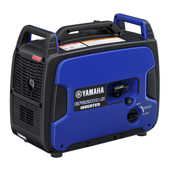
EF2200iS
7PC-F8199-U0
Advertisement
Table of Contents

Related Manuals for Yamaha EF2200iS


Summary of Contents for Yamaha EF2200iS
- Page 1 MANUAL DEL PROPIETARIO MANUAL DO PROPRIETÁRIO 사용자매뉴얼 使用说明书 本社制作課 '19.05.21 久保田 EF2200iS Read this manual carefully before operating this machine. Il convient de lire attentivement ce manuel avant la première utilisation de la machine. Bitte lesen Sie diese Bedienungsanleitung sorgfältig durch, bevor Sie die Maschine in Betrieb nehmen.
- Page 3 OWNER’S MANUAL EF2200iS Read this manual carefully before operating this machine. 7PC-F8199-U0-E0...
- Page 4 Cover2 Read this manual carefully before operating this machine. This manual should stay with this machine if it is sold.
- Page 5 Therefore, while this manual contains the most current product information available at the time of printing, there may be minor discrepancies between your machine and this manual. If there is any question concerning this manual, please consult a Yamaha dealer.
- Page 6 Important manual information Particularly important information is distinguished in this manual by the following nota- tions. This is the safety alert symbol. It is used to alert you to potential personal injury hazards. Obey all safety messages that follow this symbol to avoid possible injury or death.
-
Page 7: Table Of Contents
Troubleshooting ....... 7-1 Twin Tech (parallel running terminal)........2-9 Specifications ......8-1 Accessory socket......2-9 EF2200iS ......... 8-1 AC receptacle ......2-10 Consumer information ..9-1 Carburetor fuel drain cock ..2-10 Recoil starter....... 2-10 Machine identification ...... 9-1 Before operation.... -
Page 8: Safety Information
Safety information General safety information • This generator is not designed for on-board use. Do not use it while installed on the vehicle. • Do not modify the generator or use it with its parts removed. • Do not allow children to operate the generator. •... -
Page 9: Exhaust Fumes Are Poisonous
Safety information Exhaust fumes are poisonous • Using a generator indoors CAN KILL YOU IN MIN- UTES. Generator exhaust contains carbon monox- ide. This is a poison you cannot see or smell. • NEVER use inside a home or garage, EVEN IF doors and windows are open. -
Page 10: Engine And Muffler May Be Hot
Safety information Engine and muffler may be hot • Place the generator in a place where pedestrians or children are not likely to touch the machine. • Avoid placing any flammable materials near the exhaust outlet during operation. • In order to prevent overheating, ensure adequate air- flow by keeping the machine at least 1 m (3 ft) from objects or other equipment. -
Page 11: Connection Notes
Safety information • Never touch the generator with wet hands or electri- cal shock will occur. • Connect the ground (earth) terminal to a ground source. In order to prevent electrical shock, the gen- erator must be grounded when using an electrical device with a ground plug. -
Page 12: Extension Cord Notes
Safety information Extension cord notes Extension cords should be protected by a tough flexible rubber sheath (IEC 245) or the equivalent to withstand mechanical stresses. -
Page 13: Location Of Important Labels
Safety information Location of important labels Please read the following labels carefully before operating this machine. Maintain or replace safety and instruction labels, as necessary. For Europe 7PB-F4162-50 ***** 7PB-F8176-30... - Page 14 Safety information NOTICE LET OP ATENCIÓN FORSIKTIG ATTENTION ATTENZIONE ACHTUNG Use the specified spark plug only. Gebruik alleen de voorgeschreven bougie. Utilice únicamente la bujía especificada. Benytt kun den spesifiserte typen tennplugg. Recourir exclusivement à la bougie du type spécifié. BPR6HS (NGK) Utilizzare solamente la candela d’accensione specificata.
- Page 15 Safety information For Australia 7PB-F4877-00...
- Page 16 Safety information **** ************ ************ ************...
-
Page 17: Controls And Features
Controls and features Description Carrying handle (p. 1-1) Recoil starter (p. 2-10) Fuel tank cap air vent lever (p. 2-7) Fuel level gauge (p. 2-8) Fuel tank cap (p. 2-5) Muffler (p. 5-11) Control panel (p. 2-1) 10 Carburetor fuel drain cock (p. 2-10) Engine switch (p. - Page 18 Controls and features Control panel For Europe Twin Tech (parallel running terminal) (p. Accessory socket (p. 2-9) 2-9) Economy control switch (p. 2-6) Ground (earth) terminal (p. 2-6) Multi-function LED meter (p. 2-1) AC receptacle (p. 2-10) Boost mode switch/Reset button (p. 2-9/p. 2-7)
- Page 19 Controls and features For Australia Accessory socket (p. 2-9) Twin Tech (parallel running terminal) (p. 2-9) Economy control switch (p. 2-6) Ground (earth) terminal (p. 2-6) Multi-function LED meter (p. 2-1) AC receptacle (p. 2-10) Boost mode switch/Reset button (p. 2-9/p. 2-7) Multi-function LED meter Oil level warning light (Red) (p.
- Page 20 Controls and features This generator has an integrated multi-function LED meter. Its functions are described as below. Function Display Description Page Output indicator(s) come on Power supply meter according to the current power supply. Output indicator(s) flash ac- Operating time meter cording to the accumulated operation time.
-
Page 21: Control Function
Controls and features Control function Engine switch The engine switch controls the ignition system and the fuel cock. 1. Engine switch 2. “ ” (RUN) 3. “ ” (STOP) The engine switch of this generator opens and closes the fuel cock simultaneously. You don’t need to operate the fuel cock separately. -
Page 22: Ground (Earth) Terminal
Ground (earth) terminal connects the earth line for pre- vention of electric shock. When the electric device is grounded, be sure to ground the generator, too. For the grounding, consult a Yamaha dealer. 1. Ground (earth) terminal Economy control switch In order to reduce fuel consumption and operating noise, use the economy control switch. -
Page 23: Overload Indicator Light (Red)
Controls and features Overload indicator light (Red) The overload indicator light comes on when electricity over the rated output is required by the connected elec- trical devices, or when the inverter control unit over- heats, or the AC output voltage rises. Then the AC protector will trip, stopping power generation in order to protect the generator and any connected electric devices. -
Page 24: Fuel Level Gauge
Controls and features Fuel level gauge The fuel level gauge shows the amount of the fuel in the fuel tank. Make sure that sufficient fuel is in the fuel tank before the operation. 1. Fuel level gauge For European customers: •... -
Page 25: Boost Mode Switch
Twin Tech (parallel running terminal) The Twin Tech terminals are used for connecting two identical generators (EF2200iS) in parallel by using the dedicated cable. It cannot be connected to any other generator than the EF2200iS. -
Page 26: Ac Receptacle
Controls and features AC receptacle This generator has two AC receptacles. Before connection, confirm the shapes of the consents and the specifications of both the generator and the devices to be connected. 1. AC receptacle A For Europe B For Australia Carburetor fuel drain cock Carburetor fuel drain cock is used to discharge the remained fuel in the carburetor for long term storage. - Page 27 Controls and features NOTICE • Pull the recoil starter handle straight unless it breaks by getting caught in a part around it. • Return the recoil starter handle slowly, not to break the parts of the generator due to the impact when the recoil starter handle retracts vigorously by letting go of the hand while pulling the recoil starter handle.
-
Page 28: Before Operation
Before operation Preparation Fuel WARNING • Fuel is highly flammable and poisonous. Check “Safety information” (See page 1-1) carefully before filling. • Do not overfill the fuel tank over the red level of the fuel tank strainer, otherwise it may overflow when the fuel warms up and expands. -
Page 29: Engine Oil
Fuel tank capacity: Total: 4.7 L (1.24 US gal, 1.03 Imp gal) Your Yamaha engine has been designed to use regular unleaded gasoline with a pump octane number ((R + M)/2) of 86 or higher, or research octane number of 91 or higher. - Page 30 Before operation Remove the screws (for Europe). Or turn the panel openers to disengage the lock (for Australia). 1. Screw 2. Panel opener A For Europe B For Australia Remove the panel by detaching the hooks. 1. Hook 2. Panel...
- Page 31 Before operation Remove the oil filler cap. 1. Oil filler cap Fill the specified amount of the recommended engine oil, and then install and tighten the oil filler cap. NOTICE • Do not tilt the generator when adding engine oil. This could result in overfilling and damage to the engine.
-
Page 32: Pre-Operation Check
• Fuel line - Make sure that the fuel should not leak from the generator when turning on the engine switch. - Consult a Yamaha dealer, if necessary. • Engine oil (See page 3-2) - Check oil level in engine. -
Page 33: Operation
Operation Precautions for use WARNING • Never operate the engine in a closed area or it may cause unconsciousness and death within a short time. Operate the engine in a well venti- lated area. • Before starting the engine, do not connect any electric devices. - Page 34 Operation Turn the economy control switch to “ ”/“ ” (OFF), if necessary. 1. “ ”/“ ” (OFF) Pull the choke knob fully out. 1. Choke knob The choke is not required to start a warm engine. Push the choke knob in to the original position. Turn the engine switch to “...
-
Page 35: Stopping The Engine
Operation After the engine starts, warm up the engine until the engine does not stop when the choke knob is returned to the original position. 1. Original position When starting the engine, with the economy control switch “ ”/“ ” (ON), and there is no load on the generator: •... -
Page 36: Connecting Devices Via Alternating Current (Ac) Receptacles
Operation Turn the engine switch to “ ” (STOP). 1. “ ” (STOP) Turn the fuel tank cap air vent lever to “OFF” after the engine has completely cooled down. 1. “OFF” Connecting devices via Alternating Current (AC) receptacles WARNING Be sure any electric devices are turned off before plugging them in. - Page 37 Operation Start the engine (See page 4-1). Plug in to AC receptacle. Make sure that all the output indicators and the overload indicator light come on. 1. Output indicator (Green) 2. Overload indicator light (Red) Make sure that the output indicators and the over- load indicator light once turn off, and then the only one of the output indicators still remains on.
-
Page 38: Connecting Devices Via The Accessory Socket
Operation Connecting devices via the accessory socket WARNING Be sure any electric devices are turned off before plugging them in. NOTICE • Be sure all electric devices including the lines and plug connections are in good condition before connection to the generator. •... -
Page 39: Application Range
Operation Application range When using the generator, make sure the total load is within rated output of a generator. Otherwise, generator damage may occur. DC (Accessory socket) 0.4–0.75 Power factor 0.8–0.95 Rated voltage 12 V (Efficiency 0.85) Rated current 3 A –1800 W –1440 W –612 W... -
Page 40: High Altitude Operation
4000 ft. (1219 meters). If you operate your engine at altitudes above 4000 ft. (1219 meters) consistently, have your local Yamaha dealer perform the neces- sary carburetor modification. This engine should be operated in its original configuration below 4000 ft. -
Page 41: Periodic Maintenance
WARNING If you are not familiar with maintenance work, have a Yamaha dealer do it for you. Check before use The customer needs to perform the pre-operation check (See page 3-5). If any problems are discovered during the inspection, contact a Yamaha dealer and request an inspection or maintenance. - Page 42 *1····· Initial replacement of the engine oil is after one month or 20 hours of operation. *2····· Needs to be cleaned more frequently when using in unusually wet or dusty areas. ····· Since these items require special tools, data and technical skills, have a Yamaha dealer perform the service.
-
Page 43: Engine Oil Replacement
Periodic maintenance Engine oil replacement WARNING Avoid draining the engine oil immediately after stopping the engine. The oil is hot and should be handled with care to avoid burns. Place the generator on a level surface and warm up the engine for several minutes. Then stop the engine, then turn the engine switch to “... - Page 44 Periodic maintenance Remove the panel by detaching the hooks. 1. Hook 2. Panel Remove the oil filler cap. 1. Oil filler cap 2. O-ring Place an oil pan under the engine. Tilt the genera- tor to drain the oil completely. Check the oil filler cap and O-ring.
-
Page 45: Spark Plug Inspection
Periodic maintenance Add engine oil to the correct level. NOTICE • Do not tilt the generator when adding engine oil. This could result in overfilling and damage to the engine. • Be sure no foreign material enters the crankcase. 1. Correct level Recommended engine oil: Recommended oil brand: YAMALUBE... - Page 46 Periodic maintenance Remove the screws (for Europe). Or turn the panel openers to disengage the lock (for Australia). 1. Screw 2. Panel opener A For Europe B For Australia Remove the panel by detaching the hooks. 1. Hook 2. Panel...
- Page 47 Periodic maintenance Remove the spark plug cap and access cap, and insert the tool through the hole from the outside of the cover. 1. Spark plug cap 2. Access cap Insert the handlebar into the tool and turn it coun- terclockwise to remove the spark plug.
-
Page 48: Air Filter Cleaning
Periodic maintenance Install the spark plug cap and access cap. Install the panel. Finger-tighten the panel openers to engage the lock (for Australia). Or install the screws (for Europe). Panel screw tightening torque: 1.5 N·m (0.15 kgf·m, 1.1 lb·ft) Air filter cleaning Remove the screws (for Europe). - Page 49 Periodic maintenance Remove the panel by detaching the hooks. 1. Hook 2. Panel Remove the screw and then remove the air filter case cover. 1. Screw 2. Air filter case cover Remove the foam element. 1. Screw 2. Air filter case cover 3.
- Page 50 Periodic maintenance Wash the foam element with a foam air filter cleaner and dry it. Oil the foam element and squeeze out excess oil. The foam element should be wet but not dripping. NOTICE Do not wring out the foam element when squeezing This could cause it to tear.
-
Page 51: Muffler Screen And Spark Arrester Cleaning
Periodic maintenance Muffler screen and spark arrester cleaning WARNING The engine and muffler will be very hot after the engine has been run. Avoid touching the engine and muffler while they are still hot with any part of your body or clothing during inspection or repair. -
Page 52: Fuel Tank Strainer Cleaning
Periodic maintenance Remove the carbon deposits on the muffler cap, muffler screen and spark arrester using a wire brush. NOTICE When cleaning, use the wire brush lightly to avoid 711-075 damaging or scratching of the muffler cap, muffler screen and spark arrester. Check the muffler screen and spark arrester. -
Page 53: Carburetor Adjustment
Be sure the fuel tank cap is tightened securely. Carburetor adjustment The carburetor is a vital part of the engine. Adjusting should be left to a Yamaha dealer with the professional knowledge, specialized data, and equipment to do so properly. -
Page 54: Storage
Storage Long term storage of your machine will require some preventive procedures to guard against deterioration. Drain the fuel Turn the engine switch to “ ” (STOP). 1. “ ” (STOP) Remove the fuel tank cap and fuel tank strainer. Extract the fuel from the fuel tank into an approved gasoline container using a commercially available hand siphon. -
Page 55: Engine
Storage Drain the fuel from the carburetor by turning the carburetor fuel drain cock to “OPEN”. 1. Cap 2. Carburetor fuel drain cock WARNING Immediately wipe off spilled fuel with a rag. Fire hazard may occur. NOTICE Do not turn the carburetor fuel drain cock with any tools not to break the cock. - Page 56 Storage Remove the spark plug, pour about one table- spoon of engine oil (See page 5-3) into the spark plug hole and install and tighten the spark plug to the specified torque. Recoil start the engine by turning over several times (with ignition off) to coat the cylinder walls with oil.
-
Page 57: Trouble Recovery
Trouble recovery Troubleshooting This section describes the likely causes and remedies for problems. If your Generator requires repair, bring it to a Yamaha dealer. Engine won’t start Item Check Action Page Is there fuel in the fuel tank? Supply fuel. - Page 58 Some malfunctions have been Is the overload indicator light Overload indicator detected. Consult a Yamaha — flashing? light dealer. The reset button does not function even while the over- Consult a Yamaha dealer.
- Page 59 Add sufficient engine oil. Place Is the oil level warning light the generator on a level sur- flashing? face. For any other abnormal operating conditions not covered here, please consult a Yamaha dealer.
-
Page 60: Specifications
Specifications EF2200iS DIMENSIONS: Overall length 555 mm (21.9 in) Overall width 300 mm (11.8 in) Overall height 470 mm (18.5 in) Dry weight 25 kg (55 lb) ENGINE: Engine type Air cooled 4-stroke gasoline OHV Cylinder arrangement Inclined, 1 cylinder Displacement 79 cm³... - Page 61 Specifications ** This CO measurement results from testing over a fixed test cycle under laboratory conditions a parent engine representative of the engine family and shall not imply or express any guarantee of the performance of a particular engine.
-
Page 62: Consumer Information
Record your model type, Primary I.D., and serial num- bers in the spaces provided, to assist you in ordering spare parts from a Yamaha dealer. Also record and keep these I.D. numbers in a separate place in case your machine is stolen. -
Page 64: Wiring Diagram
Wiring diagram For Europe Br/B L/B Y/B Br P O Br/B B R/W 10-1... - Page 65 Wiring diagram Color code 1. Generator 2. DC coil Black 3. AC sub coil Brown 4. AC coil Green 5. AC/DC convertor Gray 6. Control box Blue 7. Accessory socket Orange 8. Twin Tech (parallel running terminal) Pink 9. AC receptacle 10.Multi-function LED meter Violet 11.Economy control switch...
- Page 66 Wiring diagram For Australia O G/Y Br/B L/B Y/B Br P O W Br/B G/Y Y/B R/W Br B R/W 10-3...
- Page 67 Wiring diagram Color code 1. Generator 2. DC coil Black 3. AC sub coil Brown 4. AC coil Green 5. AC/DC convertor Gray 6. Control box Blue 7. Accessory socket Orange 8. Twin Tech (parallel running terminal) Pink 9. AC receptacle 10.Multi-function LED meter Violet 11.Economy control switch...
-
Page 68: Index
Index Accessory socket ........2-9 Location of important labels .......1-6 AC receptacle.......... 2-10 Air filter cleaning........5-8 Machine identification ........9-1 Application range ........4-7 Maintenance chart ........5-1 Muffler screen and spark arrester Boost mode switch ........2-9 cleaning............5-11 Carburetor adjustment ......5-13 Oil level warning light (Red) .......2-5 Carburetor fuel drain cock....... - Page 70 Printed in China 2019.051 !
- Page 72 Original instructions Notice originale Originalbetriebsanleitung Istruzioni originali Manual original ****************** ****************** ****************** Printed in China 2019.05×1 ! (E, F, G, H, S, P, 2, C)