Yamaha EF2800i Owner's Manual
Hide thumbs
Also See for EF2800i:
- Service manual (103 pages) ,
- Owner's manual (76 pages) ,
- Theory & diagnostics manual (218 pages)

Related Manuals for Yamaha EF2800i


Summary of Contents for Yamaha EF2800i
- Page 1 Generator OWNER’S MANUAL Read this manual carefully before operating this machine. EF2800i LIT-19626-01-70 7VU-28199-16...
- Page 2 Read this manual carefully before operating this machine. This manual should stay with this machine if it is sold.
- Page 3 AE00002 INTRODUCTION Congratulations on your purchase of your new Yamaha. This manual will provide you with a good basic understanding of the operation and maintenance of this machine. If you have any questions regarding the operation or maintenance of your machine, please consult a Yamaha dealer.
- Page 4 If there is any question concerning this manu- al, please consult a Yamaha dealer. A TIP provides key information to make 9 This manual should be considered a procedures easier or clearer.
-
Page 5: Table Of Contents
ENGINE ..........37 ENGINE SWITCH ........7 GENERATOR ........37 ECONOMY CONTROL SWITCH..7 WIRING DIAGRAM.......38 DC PROTECTOR ........8 EF2800i..........38 G.F.C.I. RECEPTACLE .......9 YAMAHA MOTOR CORPORATION, PRE-OPERATION CHECK....10 U.S.A. FUEL..........10 EF SERIES GENERATORS 3-YEAR LIMITED WARRANTY....39 ENGINE OIL ........11 YAMAHA OUTDOOR POWER GROUND (earth) TERMINAL ....12 EQUIPMENT OPERATION .........13... -
Page 6: Location Of Important Labels
The air index of this engine is 3 EMISSION CONTROL INFORMATION (California only) YAMAHA MOTOR POWERED PRODUCTS CO.,LTD. This engine meets 20** California exhaust and evaporative emission regulations for small off-road engines. THIS ENGINE MEETS U.S. EPA EXH EVP REGS FOR 20**. -
Page 7: Safety Information
AE00071 SAFETY INFORMATION 9 This generator is not designed for on-board use. Do not use it while installed on the vehicle. 9 Do not modify the generator or use it with its parts removed. 9 Do not allow children to operate the generator. 9 Be sure to carry the generator only by its carrying handle(s). -
Page 8: Fuel Is Highly Flammable And Poisonous
AE00075 FUEL IS HIGHLY FLAMMABLE AND POISONOUS 9 Always turn off the engine when refuelling. 9 Never refuel while smoking or in the vicinity of an open flame. 741-003 9 Take care not to spill any fuel on the engine or muffler when refuelling. -
Page 9: Electric Shock Prevention
9 Do not operate the engine with a dust cover or other objects covering it. 9 When covering the generator, be sure to do so only after the engine and muffler have completely cooled down. 741-009 7VU-002 AE00083 ELECTRIC SHOCK PREVENTION 9 Never operate the engine in rain or snow. -
Page 10: Connection Notes
AE00088 CONNECTION NOTES 9 Avoid connecting the generator to commercial power outlet. 9 Avoid connecting the generator in parallel with any other generator. 1 Correct 2 Incorrect AE00091 CONNECTION WARNING Before the generator can be connected to a build- ing’s electrical system, a licensed electrician must install an isolation (transfer) switch in the build- ing’s main fuse box. -
Page 11: Control Function
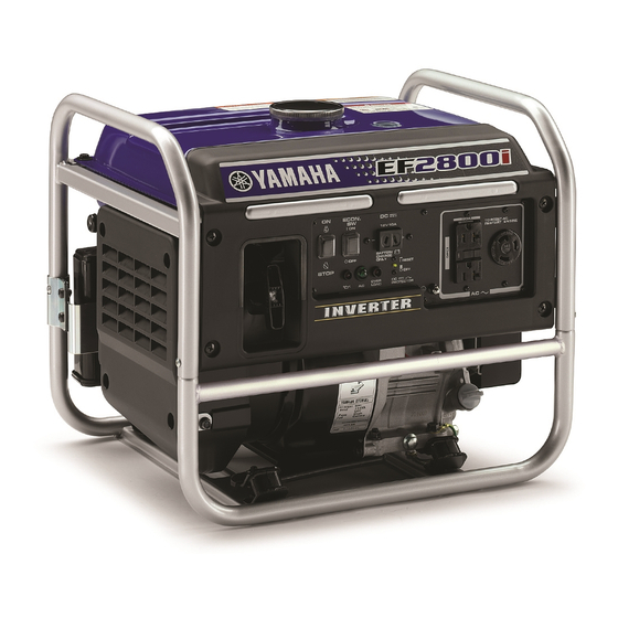
AE00101 EF2800i CONTROL FUNCTION AE00102 DESCRIPTION 1 Carrying handles (shaded) 2 Fuel tank 3 Fuel tank cap 4 Fuel level gauge 5 Ground (earth) terminal 6 Oil filler cap 7 Oil drain bolt 793-084 8 Recoil starter 9 Choke knob... -
Page 12: Oil Warning Light (Red)
AE00111 OIL WARNING LIGHT (red) When the oil level falls below the lower level, the oil warning light (red) comes on and then the engine stops automatically. Unless you refill with oil, the engine will not start again. If the engine stalls or does not start, turn the engine switch to “ON”... -
Page 13: Dc Protector
Reduce the load of the connected electric device below the specified rated output of the generator if the DC protector turns off. If the DC protector turns off again, stop using the device immediately and consult a Yamaha dealer. – 8 –... -
Page 14: G.f.c.i. Receptacle
AE00848 G.F.C.I. RECEPTACLE The G.F.C.I. (Ground Fault Circuit Interrupter) shuts off power to the protected receptacles if a ground fault (electrical leak) is detected. If the reset button pops out, the equipment plugged into the receptacle may be faulty. If this happens, 763-105a check the equipment carefully. -
Page 15: Pre-Operation Check
Fuel tank capacity: 707-033a Total: 9.7 L (2.55 US gal, 2.12 Imp gal) Your Yamaha engine has been designed to use regu- lar unleaded gasoline with a pump octane number ((R + M)/2) of 86 or higher, or research octane number of 91 or higher. -
Page 16: Engine Oil
WARNING 9 Fuel is highly flammable and poisonous. Check “SAFETY INFORMATION” (See page 2) carefully before refueling. 9 Do not fill above the top of the fuel filter or it may overflow when the fuel warms up and expands. 9 After refueling, make sure the tank cap is tight- ened securely. -
Page 17: Ground (Earth) Terminal
0°C 25°C Recommended engine oil: å YAMALUBE 4 (10W-40), å YAMALUBE 4 (10W-40) SAE 10W-30 or 10W-40 ∫ SAE #30 ç SAE #20 ∂ SAE 10W ç SAE #20 ∫ SAE #30 ∂ SAE 10W Recommended engine oil grade: 32°F 80°F API Service SE type or higher Engine oil quantity:... -
Page 18: Operation
AE00955 OPERATION WARNING 9 Never operate the engine in a closed area or it 761-073 may cause unconsciousness and death within a short time. Operate the engine in a well ven- tilated area. 9 Before starting the engine, do not connect any electric devices. - Page 19 4. Pull the choke knob fully out. 1 Choke knob The choke is not required to start a warm engine. 701-047b Push the choke knob in to the original position. 5. Pull slowly on the recoil starter until it is engaged, then pull it briskly.
-
Page 20: Application Range
When using the generator, make sure the total load is within rated output of a generator. Otherwise, generator damage may occur. 0.4–0.75 Power factor 0.8–0.95 (Efficiency 0.85) Rated voltage EF2800i –2,500W –2,000W –850W Rated current 9 “–” means below. 9 Application wattage indicates when each device is used by itself. -
Page 21: Connection
AE01001 CONNECTION Alternating Current (AC) WARNING Be sure any electric devices are turned off before plugging them in. NOTICE 9 Be sure all electric devices including the lines and plug connections are in good condition before connection to the generator. 9 Be sure the total load is within generator rated output. - Page 22 4. Turn the economy control switch to “ON” and turn on any electric devices. 1 I “ON” The economy control switch must be turned to “OFF” 763-129a when using electric devices that require a large start- ing current, such as a compressor or a submergible pump.
-
Page 23: Battery Charging
BATTERY CHARGING NOTICE Do not connect a VRLA (Valve Regulated Lead Acid) battery. To charge a VRLA battery, a special (constant-voltage) battery charger is required. 9 The generator DC rated voltage is 12V. 9 Start the engine first, and then connect the gener- ator to the battery for charging. - Page 24 To restart charging the battery, turn the DC protector on by pressing its button to “RESET”. If the DC protector turns off again, stop charging the battery immediately and consult a Yamaha dealer. – 19 –...
- Page 25 9 Follow instructions in the owner’s manual for the battery to determine the end of battery charging. 9 Measure the specific gravity of electrolyte to deter- mine if the battery is fully charged. At full charge, the electrolyte specific gravity is between 1.26 and 1.28.
- Page 26 Operating range of DC power supply (exclusively for charging 12V battery) This power source is designed to charge batteries up to 40Ah that are half-discharged. Do not charge batter- ies of a higher capacity than 40Ah. 12V battery The time required for recharging a battery varies depending on the discharge level of the battery.
-
Page 27: Stopping The Engine
AE00992 STOPPING THE ENGINE Turn off any electric devices. 1. Turn the economy control switch to “OFF ”. 1 3 “OFF” 763-126b 2. Disconnect any electric devices. 761-073 3. Turn the engine switch to “STOP”. 1 5 “STOP” 763-085e 4. Turn the fuel cock lever to “OFF”. 1 “OFF”... -
Page 28: Periodic Maintenance
The most impor- tant points of generator inspection, adjustment, and lubrication are explained on the fol- lowing pages. WARNING If you are not familiar with maintenance work, have a Yamaha dealer do it for you. AE00403 MAINTENANCE CHART WARNING Stop the engine before starting maintenance work. - Page 29 *1·····Initial replacement of the engine oil is after one month or 20 hours of operation. *2·····The air filter element needs to be cleaned more frequently when using in unusually wet or dusty areas. #····· Since these items require special tools, data and technical skills, have a Yamaha dealer perform the ser- vice.
-
Page 30: Spark Plug Inspection
6. Install the spark plug cap. AE00431 CARBURETOR ADJUSTMENT The carburetor is a vital part of the engine. Adjusting should be left to a Yamaha dealer with the profession- al knowledge, specialized data, and equipment to do so properly. – 25 –... -
Page 31: Engine Oil Replacement
AE00972 ENGINE OIL REPLACEMENT WARNING Avoid draining the engine oil immediately after stopping the engine. The oil is hot and should be handled with care to avoid burns. 1. Place the generator on a level surface and warm up the engine for several minutes. Then stop the engine. -
Page 32: Muffler Screen And Spark Arrester
0°C 25°C Recommended engine oil: å YAMALUBE 4 (10W-40), å YAMALUBE 4 (10W-40) SAE 10W-30 or 10W-40 ∫ SAE #30 ç SAE #20 ∂ SAE 10W ç SAE #20 ∫ SAE #30 ∂ SAE 10W Recommended engine oil grade: 32°F 80°F API Service SE type or higher Engine oil quantity:... - Page 33 3. Remove the spark arrester. 1 Spark arrester 711-054e 4. Remove the carbon deposits on the muffler screen and spark arrester using a wire brush. NOTICE When cleaning, use the wire brush lightly to avoid damaging or scratching of the muffler screen and spark arrester.
-
Page 34: Air Filter
AE00451 AIR FILTER 1. Remove the screws, and then remove the air filter case cover. 2. Remove the foam element. 1 Screws 2 Air filter case cover 3 Foam element 3. Wash the foam element in solvent and dry it. WARNING Never use solvent while smoking or in the vicinity of an open flame. -
Page 35: Fuel Cock
FUEL COCK WARNING Never use the gasoline while smoking or in the vicinity of an open flame. 1. Turn the fuel cock lever to “OFF”. 2. Remove the fuel cock cup, gasket, and fuel strainer. 3. Clean the cup and strainer with gasoline and wipe it off. -
Page 36: G.f.c.i. Receptacle Test
Incorrect 3. If G.F.C.I. operation is correct, push in the reset button. If the G.F.C.I. operates incorrectly, consult a Yamaha dealer. WARNING Do not operate the generator with a faulty G.F.C.I. circuit. Electric shock could occur. Have the gen- erator repaired by a qualified mechanic. -
Page 37: Troubleshooting
704-016 Poor spark 2 Spark plug dirty with carbon or wet ..Remove carbon or wipe spark plug dry. 2 Faulty ignition system ..Consult a Yamaha deal- 791-001d AE00785 Generator won’t produce power 2 Safety device (AC) to “OFF” ..Stop the engine, then restart. - Page 38 Replace or Clean the spark adjust gap. plug. Dose not spark Clean Check the following O Clogged 9 Fuel line clogging replace Engine does not start. 9 Air cleaner element clogging. Consult a Yamaha dealer. – 33 –...
-
Page 39: Storage
AE00601 STORAGE Long term storage of your generator will require some preventive procedures to guard against deterioration. AE00611 DRAIN THE FUEL 1. Turn the engine switch to “STOP”. 1 5 “STOP” 2. Remove the fuel tank cap. Extract the fuel from the fuel tank into an approved gasoline container using a commercially available handsiphon. -
Page 40: Engine
6. Drain the fuel remaining in the carburetor into an approved container by loosening the drain screw on the carburetor float chamber. 1 Drain screw 7. Tighten the drain screw. 7VU-004 8. Turn the engine switch to “OFF”. 9. Turn the fuel cock lever to “OFF”. 10. -
Page 41: Exhaust Emission Control System And Components
AND LATER SMALL OFF-ROAD ENGINES. The acronyms conform to the latest version of the SAE’s recommended prac- tice document J1930, “Diagnostic Acronyms, Terms, and Definitions For Electrical/Electronic System”. It is recommended that these items be serviced by a Yamaha dealer. – 36 –... -
Page 42: Specifications
AE00701 SPECIFICATIONS AE00702 DIMENSIONS Unit EF2800i Overall Length mm (in) 487 (19.2) Overall Width mm (in) 395 (15.6) Overall Height mm (in) 425 (16.7) Dry Weight kg (lb) 31 (66.1) AE00704 ENGINE EF2800i Unit Type Air cooled 4-stroke gasoline OHV... -
Page 43: Wiring Diagram
AE00751 WIRING DIAGRAM EF2800i 1 Main coil 770-038b 2 Sub coil Color code 3 DC rectifier Black 4 Control unit Brown 5 AC pilot light Green 6 AC receptacle Gray 7 G.F.C.I. receptacle Blue 8 Ground (earth) terminal Orange 9 Economy control switch... -
Page 44: Yamaha Motor Corporation
Yamaha generator service dealer will, All 1995 and Later EF Models free of charge, repair or replace, at Yamaha’s Two (2) years from the original purchase date option, any part judged defective by Yamaha due to faulty workmanship or material from the factory. - Page 45 TIAL DAMAGES, SO THE ABOVE EXCLUSION MAY NOT APPLY TO YOU. THIS WARRANTY GIVES YOU SPECIFIC LEGAL RIGHTS, AND YOU MAY ALSO HAVE OTHER RIGHTS WHICH VARY FROM STATE TO STATE. YAMAHA MOTOR CORPORATION, U.S.A. Post Office Box 6555 Cypress, California 90630 – 40 –...
- Page 46 Yamaha Motor exactly as specified in the Owner’s Manual? Corporation, U.S.A. by the selling dealer at the A. No. The warranty on a new Yamaha cannot time of your purchase. If you should move after be “voided” or “cancelled.”...
-
Page 47: Yamaha Outdoor Power
If any evaporative emission- coverage, you should contact Yamaha Customer related part on your equipment is defective, the Relations at 1-800-962-7926. part will be repaired or replaced by Yamaha. YAMAHA MOTOR CORPORATION, USA Post Office Box 6555 Cypress, California 90630... -
Page 48: Yamaha Motor Corporation
Yamaha recommends that you retain all receipts covering maintenance on your SORE engine, but Yamaha cannot deny warranty solely for the lack of receipts or for your failure to ensure the performance of all scheduled maintenance. - Page 49 instructions required by subsection (d) must be warranted for the warranty period defined in Subsection (b)(2). If any such part fails during the period of warranty coverage, it must be repaired or replaced by the manufacturer according to Subsection (4) below. Any such part repaired or replaced under the warranty must be warranted for the remaining warranty period.
- Page 50 This work must be done at an authorized Yamaha dealer. Give notice to an authorized Yamaha dealer of any apparent defects(s) within a reasonable period of time after discovery. The SORE engine must be made available for inspection by an authorized Yamaha dealer.
- Page 51 This warranty does not cover damage resulting from accidents, acts of nature, or other events or occur- rences beyond the control of Yamaha. Yamaha Motor Corporation, U.S.A. expressly disclaims responsi- bility for any and all consequential damages, such as loss of time, inconvenience, loss or use of the SORE engine, or commercial loss.
-
Page 52: Yamaha Extended Service (Y.e.s.)
9 Y.E.S. is flexible. You can choose the plan that’s right for you: 12 months, 24 months or 36 months coverage. 9 Y.E.S. is administered by the same Yamaha people that handle your warranty - and it shows in the comprehensive coverage benefits. There are no hour limitations and Y.E.S. covers manufacturing defects just like your warranty. - Page 54 PRINTED IN JAPAN 2011.03-0.3×1 ! PRINTED ON RECYCLED PAPER...