
Related Manuals for Yamaha EF2400iSHC


Summary of Contents for Yamaha EF2400iSHC
- Page 1 Generator OWNER’S MANUAL Read this manual carefully before operating this machine. EF2400iSHC LIT-19626-02-18 7CF-28199-19 0...
- Page 2 Read this manual carefully before operating this machine. This manual should stay with this machine if it is sold.
- Page 3 AE00002 INTRODUCTION Congratulations on your purchase of your new Yamaha. This manual will provide you with a good basic understanding of the operation and maintenance of this machine. If you have any questions regarding the operation or maintenance of your machine, please consult a Yamaha dealer.
- Page 4 A WARNING indicates a hazardous sit- OPERATING THE MACHINE. uation which, if not avoided, could result in death or serious injury. 9 Yamaha continually seeks advance- NOTICE ments in product design and quality. A NOTICE indicates special precau- Therefore, while this manual contains...
-
Page 5: Table Of Contents
Extension cord notes ......4 Machine identification ....... 38 LOCATION OF IMPORTANT WIRING DIAGRAM ......39 LABELS ..........5 YAMAHA EXTENDED SERVICE DESCRIPTION ........7 (Y.E.S.) ..........40 Control panel ........7 Engine switch ........8 Oil warning light (red) ......8 DC protector ........ -
Page 6: Safety Information
AE00071 SAFETY INFORMATION 9 This generator is not designed for on-board use. Do not use it while installed on the vehicle. 9 Do not modify the generator or use it with its parts removed. 9 Do not allow children to operate the generator. 9 Be sure to carry the generator only by its carrying handles. -
Page 7: Exhaust Fumes Are Poisonous
AE00072 Exhaust fumes are poisonous 9 Using a generator indoors CAN KILL YOU IN MINUTES. Generator exhaust contains carbon monoxide. This is a poison you cannot see or smell. 9 NEVER use inside a home or garage, EVEN IF 741-112 doors and windows are open. -
Page 8: Electric Shock Prevention
9 Avoid placing any flammable materials near the exhaust outlet during operation. 741-117 9 In order to prevent overheating, ensure adequate airflow by keeping the machine at least 1 m (3 ft) from objects or other equipment. 741-118 9 Do not operate the engine with a dust cover or other objects covering it. -
Page 9: Connection Notes
AE01181 Connection notes 9 Avoid connecting the generator to commercial power outlet. 9 Avoid connecting the generator in parallel with any other generator. 1 Correct 2 Incorrect AE00091 Connection WARNING Before the generator can be connected to a build- ing’s electrical system, a licensed electrician must install an isolation (transfer) switch in the build- ing’s main fuse box. -
Page 10: Location Of Important Labels
AE00062 LOCATION OF IMPORTANT LABELS Please read the following labels carefully before oper- ating this generator. Maintain or replace safety and instruction labels, as necessary. DANGER Using a generator indoors CAN KILL YOU IN MINUTES. Generator exhaust contains carbon monoxide. This is a poison you cannot see or smell. - Page 11 DISPLACEMENT : NOTICE Use the specified spark plug only. Specified plug:BPR4ES(NGK) AC output 60Hz Rated 2.0KVA 120V HOT EXHAUST Phase Single DC output 12V 8A 7WL-28176-10 Fuel Gasoline YAMAHA MOTOR POWERED PRODUCTS CO.,LTD. MADE IN JAPAN 7CF-24164-E0 – 6 –...
-
Page 12: Description
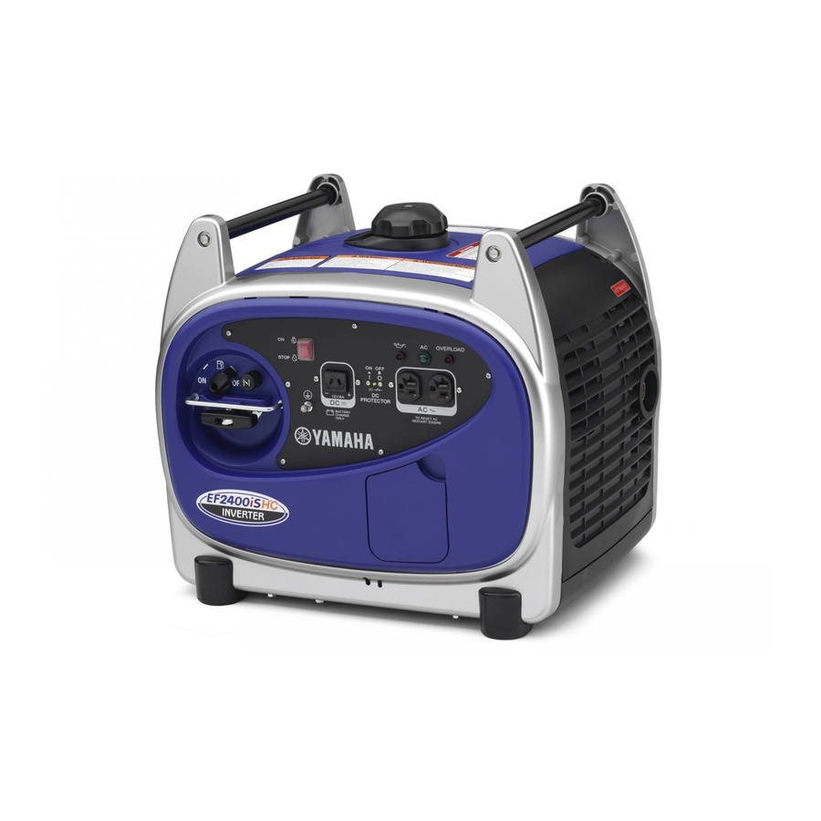
AE00101 DESCRIPTION 1 Carrying handles (shaded) 2 Fuel level gauge 3 Fuel tank cap 4 Oil filler cap 5 Recoil starter 6 Fuel cock 7 Muffler 793-147 AE00103 Control panel 2 3 4 5 1 Engine switch 2 DC protector 3 Oil warning light 4 AC pilot light 5 Overload indicator light... -
Page 13: Engine Switch
Reduce the load of the connected electric device below the specified rated output of the generator if the DC protector turns off. If the DC protector turns off again, stop using the device immediately and consult a Yamaha dealer. – 8 –... -
Page 14: Preparation
PREPARATION AE00857 Fuel WARNING 9 Fuel is highly flammable and poisonous. Check “SAFETY INFORMATION” (See page 2) carefully before filling. 9 Do not overfill the fuel tank, otherwise it may overflow when the fuel warms up and expands. 9 After fill the fuel, make sure the fuel tank cap is tightened securely. -
Page 15: Engine Oil
Full 5 “F” Empty 6 “E” Recommended fuel: Unleaded gasoline Fuel tank capacity: 7DF-020 Total: 6.0 L (1.59 US gal, 1.32 Imp gal) Engine oil NOTICE The generator has been shipped without engine oil. Do not start the engine until you have filled it with the sufficient engine oil. -
Page 16: Ground (Earth)
0°C 25°C Recommended engine oil: A YAMALUBE 4 (10W-40), å YAMALUBE 4 (10W-40) SAE 10W-30 or 10W-40 B SAE #30 ç SAE #20 C SAE #20 D SAE 10W 32°F 80°F Recommended engine oil grade: API Service SE type or higher Engine oil quantity: 0.6 L (0.63 US qt, 0.53 Imp qt) 4. -
Page 17: Pre-Operation Check
9 Check oil level in engine. 9 If necessary, add recommended oil to specified level. 9 Check generator for oil leakage. The point where abnormality was recognized by 9 Check operation. 9 If necessary, consult a Yamaha dealer. – 12 –... -
Page 18: Operation
AE00955 OPERATION WARNING 9 Never operate the engine in a closed area or it may cause unconsciousness and death within a short time. Operate the engine in a well ven- tilated area. 9 Before starting the engine, do not connect any electric devices. - Page 19 4. Pull the recoil starter slowly until it is engaged, then pull it briskly. WARNING Be careful to use the recoil starter. In rare cases, the recoil starter handle can be drawn back quick- ly by the engine kickback. Grasp the carrying handle firmly to prevent the gener- ator from falling over when pulling the recoil starter.
-
Page 20: Application Range
Otherwise, generator damage may occur. 0.4–0.75 Power factor 0.8–0.95 (Efficiency 0.85) Rated voltage 12 V EF2400iSHC –2,000 W –1,600 W –680 W Rated current 9 “–” means below. 9 Application wattage indicates when each device is used by itself. -
Page 21: High Altitude Operation
4000 ft. (1219 meters). If you operate your engine at altitudes above 4000 ft. (1219 meters) consistently, have your local Yamaha dealer perform the necessary carburetor modification. This engine should be operated in its original config- uration below 4000 ft. -
Page 22: Connection
AE01172 Connection Alternating Current (AC) WARNING Be sure any electric devices are turned off before plugging them in. NOTICE 9 Be sure all electric devices including the lines and plug connections are in good condition before connection to the generator. 9 Be sure the total load is within generator rated output. - Page 23 AE00788 Overload indicator light (red) The overload indicator light (red) comes on when an overload of a connected electrical device is detected, the inverter control unit overheats, or the AC output voltage rises. The electronic breaker will then activate, stopping power generation in order to protect the gen- erator and any connected electric devices.
- Page 24 Battery charging NOTICE 9 Do not connect a VRLA (Valve Regulated Lead Acid) battery. To charge a VRLA battery, a spe- cial (constant-voltage) battery charger is required. 9 Do not use AC and DC power at the same time or the generator may be damaged. 9 The generator DC rated voltage is 12V.
- Page 25 “ ” (ON). If the DC protector turns off again, stop charg- ing the battery immediately and consult a Yamaha dealer. 9 Follow instructions in the owner’s manual for the battery to determine the end of battery charging.
- Page 26 Operating range of DC power supply (exclusively for charging 12 V battery) This power source is designed to charge batteries up to 40 Ah that are half-discharged. Do not charge bat- teries of a higher capacity than 40 Ah. 12 V battery The time required for recharging a battery varies depending on the discharge level of the battery.
-
Page 27: Stopping The Engine
AE01173 Stopping the engine 1. Turn off any electric devices. 2. Disconnect any electric devices. 3. Turn the engine switch to the “5” (STOP). 1 “5” (STOP) 763-262 4. Turn the fuel cock lever to OFF. 2 OFF 705-075a – 22 –... -
Page 28: Periodic Maintenance
The most impor- tant points of generator inspection, adjustment, and lubrication are explained on the fol- lowing pages. WARNING If you are not familiar with maintenance work, have a Yamaha dealer do it for you. AE00403 Maintenance chart WARNING Stop the engine before starting maintenance work. - Page 29 *2 ..The air filter element needs to be cleaned more frequently when using in unusually wet or dusty areas. ★ ..Since these items require special tools, data and technical skills, have a Yamaha dealer per- form the service.
-
Page 30: Spark Plug Inspection
AE01051 Spark plug inspection The spark plug is an important engine component, which should be checked periodically. 1. Remove the side cover screws and the side cover. 1 Side cover screw 788-014 2 Side cover 2. Remove the spark plug cap and the spark plug. 3 Spark plug cap 3. -
Page 31: Carburetor Adjustment
AE00431 Carburetor adjustment The carburetor is a vital part of the engine. Adjusting should be left to a Yamaha dealer with the professional knowledge, specialized data, and equipment to do so properly. AE01174 Engine oil replacement WARNING Avoid draining the engine oil immediately after stopping the engine. -
Page 32: Muffler Screen And Spark Arrester
6. Install a new gasket and the oil drain bolt, and then tighten the bolt. Oil drain bolt tightening torque: 17 Nm (1.7 m·kgf, 12 ft·lbf) 7. Add engine oil to the correct level. NOTICE Be sure no foreign material enters the crankcase. 7 Correct level Recommended engine oil: A YAMALUBE 4 (10W-40),... - Page 33 2. Loosen the muffler cap bolt and then remove the muffler cap and muffler screen. 3 Muffler cap bolt 4 Muffler cap 5 Muffler screen 711-077 3. Use a flathead screw driver to pry the spark arrester out from the muffler. 711-078 4.
-
Page 34: Air Filter
8. Install the muffler screen and muffler cap, and tighten the muffler cap bolt. Muffler cap bolt tightening torque: 3.5 Nm (0.35 m·kgf, 2.5 ft·lbf) 711-081 9. Install the muffler cover and then tighten the muf- fler cover screws. 9 Muffler cover 0 Muffler cover screw 788-016a E01175... -
Page 35: Fuel Tank Filter
Recommended oil: Foam-air-filter oil or engine oil (See page 26) 6. Insert the foam element into the air filter case. NOTICE The engine should never run without the foam ele- ment; excessive piston and cylinder wear may result. Be sure the foam element sealing surface matches the air filter so there is no air leak. -
Page 36: Troubleshooting
763-261a Poor spark 2 Spark plug dirty with carbon or wet ..Remove carbon or wipe spark plug dry. 2 Faulty ignition system ..Consult a Yamaha deal- 791-001d AE00785 Generator won’t produce power 2 Safety device (AC) to “3” (OFF) .. - Page 37 Replace or Clean the spark adjust gap. plug. Does not spark Q Clean or replace; Consult a Check the following. O Clogged Yamaha dealer. 9 Fuel line clogging 9 Air filter element Consult a Yamaha dealer. clogging – 32 –...
-
Page 38: Storage
AE00601 STORAGE Long term storage of your generator will require some preventive procedures to guard against deterioration. AE01177 Drain the fuel 1. Turn the engine switch to “5” (STOP). 1 “5” (STOP) 763-262 2. Remove the fuel tank cap. Extract the fuel from the fuel tank into an approved gasoline container using a commercially available hand siphon. - Page 39 6. Remove the side cover screws, and then remove the side cover. 4 Side cover screw 5 Side cover 788-014 7. Drain the fuel remaining in the carburetor into an approved container by loosening the drain screw on the carburetor float chamber. 6 Drain screw 8.
-
Page 40: Engine
AE00621 Engine Perform the following steps to protect the cylinder, pis- ton ring, etc. from corrosion. 1. Remove the spark plug, pour about one table- spoon of engine oil (See page 26) into the spark plug hole and install the spark plug. Recoil start the engine by turning over several times (with igni- tion off) to coat the cylinder walls with oil. -
Page 41: Exhaust Emission Control System And Components
ROAD ENGINES. The acronyms conform to the latest version of the SAE’s recommended practice docu- ment J1930, “Diagnostic Acronyms, Terms, and Definitions For Electrical/Electronic System”. It is recommended that these items be serviced by a Yamaha dealer. – 36 –... -
Page 42: Specifications
AE00701 SPECIFICATIONS AE00702 Dimensions Unit EF2400iSHC Overall length mm (in) 527 (20.7) Overall width mm (in) 419 (16.5) Overall height mm (in) 461 (18.1) Dry weight kg (lb) 34 (75) AE00704 Engine Unit EF2400iSHC Type Air cooled 4-stroke gasoline OHV... -
Page 43: Consumer Information
PRI-I.D. NUMBER AE00012 Identification number records Record your Primary I.D., and serial num- MODEL bers in the spaces provided, to assist you in ordering spare parts from a Yamaha dealer. PRI-I.D. Also record and keep these I.D. numbers SERIAL No. CODE in a separate place in case your machine is stolen. -
Page 44: Wiring Diagram
AE00751 WIRING DIAGRAM G/Y G/Y Color code 1 Main coil Black 2 DC coil Brown 3 Sub coil Green 4 DC rectifier Blue 5 Control unit Orange 6 AC pilot light 7 AC receptacle White 8 Ground (earth) terminal Yellow 9 Overload indicator light Black/White 0 DC receptacle... -
Page 45: Yamaha Extended Service (Y.e.s.)
9 Y.E.S. is flexible. You can choose the plan that’s right for you: 12 months, 24 months or 36 months coverage. 9 Y.E.S. is administered by the same Yamaha people that handle your warranty - and it shows in the comprehensive coverage benefits. There are no hour limitations and Y.E.S. covers manufacturing defects just like your warranty. - Page 48 PRINTED IN JAPAN 2015.03-0.5×1 !