
Related Manuals for Yamaha EF2200iS


Summary of Contents for Yamaha EF2200iS
- Page 1 OWNER’S MANUAL EF2200iS Read this manual carefully before operating your Yamaha generator. LIT-19626-02-81 7PC-F8199-12...
- Page 2 Cover2 Read this manual carefully before operating your Yamaha generator. This man- ual should stay with this generator if it is sold.
- Page 3 Therefore, while this manual contains the most current product information available at the time of printing, there may be minor discrepancies between your generator and this manual. If there is any question concerning this manual, please consult a Yamaha dealer.
- Page 4 Important Manual Information Particularly important information is distinguished in this manual by the following nota- tions. This is the safety alert symbol. It is used to alert you to potential personal injury hazards. Obey all safety messages that follow this symbol to avoid possible injury or death.
-
Page 5: Table Of Contents
Boost Mode Switch ..... 2-12 Troubleshooting ....... 7-1 Twin Tech (Parallel Running Specifications ......8-1 Terminal)........2-12 EF2200iS ......... 8-1 Accessory Socket ....... 2-13 AC Receptacle......2-13 Consumer Information ..9-1 Carburetor Fuel Drain Cock..2-14 Generator Identification....9-1 Recoil Starter ...... - Page 6 Contents Exhaust Emission Control System and Components ... 10-1 Wiring Diagram....11-1 Yamaha Extended Service (Y.E.S.)........12-1 Index........13-1...
-
Page 7: Safety Information
Safety Information General Safety Information • This generator is not designed for on-board use. Do not use it while installed on the vehicle. • Do not modify the generator or use it with its parts removed. • Do not allow children to operate the generator. •... -
Page 8: Fuel Is Highly Flammable And Poison- Ous
Safety Information monoxide poisoning prior to restart the generator. • Install battery-operated or plug-in carbon monoxide alarms to alert you to potentially dangerous levels of carbon monoxide in accordance with the alarm’s instructions. Fuel is Highly Flammable and Poison- • Always turn off the engine when refuelling. •... -
Page 9: Connection Notes
Safety Information (earthed), always ground (earth) the generator. • Connect the ground (earth) terminal to a ground source. In order to prevent electrical shock, the gen- erator must be grounded when using an electrical device with a ground plug. 1. Ground (earth) terminal Connection Notes •... -
Page 10: Location Of Important Labels
Safety Information Location of Important Labels Please read the following labels carefully before operating this generator. Maintain or replace safety and instruction labels, as necessary. - Page 11 Safety Information **** ************ ************ ************...
-
Page 12: Controls And Features
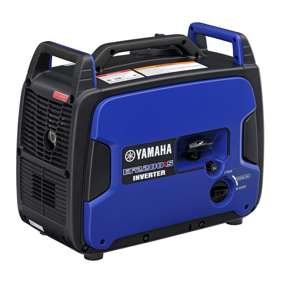
Controls and Features Description Carrying handle Choke knob Fuel tank cap air vent lever (p. 2-11) Recoil starter (p. 2-14) Fuel tank cap (p. 2-9) Fuel level gauge (p. 2-11) Control panel Muffler (p. 5-9) Engine switch (p. 2-5) 10 Carburetor fuel drain cock (p. 2-14) - Page 13 Controls and Features Control Panel Accessory socket (p. 2-13) ERR (Error) indicator light (Orange) (p. 2-5) Twin Tech (parallel running terminal) Economy control switch (p. 2-9) (p. 2-12) Multi-function LED meter Ground (earth) terminal (p. 2-9) Boost mode switch/Reset button AC receptacle (p.
- Page 14 Controls and Features Multi-Function LED Meter Oil level warning light (Red) (p. 2-5) Overload indicator light (Red) (p. 2-10) Output indicator (Green) (p. 2-10)
- Page 15 Controls and Features This generator has an integrated multi-function LED meter. Its functions are described as below. Function Display Description Page Output indicator(s) come on Power supply meter according to the current power 2-10 supply. Output indicator(s) flash ac- Operating time meter cording to the accumulated 2-11 operation time.
-
Page 16: Control Function
Controls and Features Control Function Engine Switch The engine switch controls the ignition system and the fuel cock. 1. Engine switch 2. “ ” (RUN) 3. “ ” (STOP) The engine switch of this generator opens and closes the fuel cock simultaneously. You don’t need to operate the fuel cock separately. - Page 17 Controls and Features WARNING • Do not remove or modify the CO SENSOR sys- tem. • The CO SENSOR cannot prevent all danger asso- ciated with or caused by carbon monoxide. Pay careful attention to the location of the generator. •...
- Page 18 California legislature. When you dis- card the lithium battery in California, USA, please fol- low the related regulations in advance. Perchlorate material-special handling may apply, see www.dtsc.ca.gov/hazardouswaste/perchlorate • Consult a Yamaha dealer for the CO SENSOR replacement.
- Page 19 WARNING • If the indicator lights do not flash 5 times upon starting, discontinue generator use immediately and consult a Yamaha dealer. The CO SENSOR system may be malfunctioning. • If the CO SENSOR WARNING indicator light (red) is flashing, immediately clear the area of all peo- ple and animals while moving the generator to an open, outdoor area.
-
Page 20: Ac Switch (N.f.b.)
NOTICE Reduce the load to the specified generator AC rated output if the AC switch (N.F.B.) turns off. If it turns off again, consult a Yamaha dealer. Fuel Tank Cap Remove the fuel tank cap by turning it counterclock- wise. -
Page 21: Power Supply Display
Controls and Features (OFF), the engine runs at the rated speed (4900 r/min) regardless of whether a load is connected or not. • The economy control switch must be turned to “ ” (OFF) when using electric devices that require a large starting current, such as a compressor or a submersible pump. -
Page 22: Reset Button
Controls and Features Reset Button If an overload has been detected, the circuit breaker has activated, and the generator output has been stopped, stop any connected electrical devices and hold the reset button for 3 seconds. The breaker will be reset and the output will resume. 1. -
Page 23: Boost Mode Switch
Twin Tech (Parallel Running Terminal) Two EF2200iS generators can be operated in parallel to increase the rated output to 3.6 kVA and the rated current to 30.0 A. For parallel operation, use only a special Twin Tech cable (optional equipment) approved by Yamaha;... -
Page 24: Accessory Socket
Controls and Features NOTICE To avoid severe damage to the generators or other equipment: • Never attempt to parallel Yamaha generators of different outputs or a Yamaha generator with any other brand. • Connect the Twin Tech cable to the generators before starting the generators and turn off the generators before disconnecting them. -
Page 25: Carburetor Fuel Drain Cock
Controls and Features Carburetor Fuel Drain Cock Carburetor fuel drain cock is used to discharge the remained fuel in the carburetor for long term storage. Before operation, make sure that the carburetor fuel drain cock is in “CLOSED”. 1. Carburetor fuel drain cock 2. -
Page 26: Before Operation
Before Operation Preparation Fuel WARNING • Fuel is highly flammable and poisonous. Check “Safety information” (See page 1-1) carefully before filling. • Do not overfill the fuel tank over the red level of the fuel tank strainer, otherwise it may overflow when the fuel warms up and expands. -
Page 27: Engine Oil
Fuel Tank Capacity: Total: 4.7 L (1.24 US gal, 1.03 Imp gal) Your Yamaha engine has been designed to use regular unleaded gasoline with a pump octane number ((R + M)/2) of 86 or higher, or research octane number of 91 or higher. - Page 28 Before Operation Remove the screws. 1. Screw Remove the panel by detaching the hooks. 1. Hook 2. Panel Remove the oil filler cap. 1. Oil filler cap Fill the specified amount of the recommended engine oil, and then install and tighten the oil filler cap.
-
Page 29: Pre-Operation Check
Before Operation NOTICE • Do not tilt the generator when adding engine oil. This could result in overfilling and damage to the engine. • Be sure no foreign material enters the crankcase. 1. Correct level Recommended Engine Oil: Recommended oil brand: YAMALUBE Available oil grade: API SE type or higher JASO MA or MB... - Page 30 • Fuel Line - Visually inspect for any fuel leaks once the engine switch is turned on. - Any fuel leaks noticed, consult a Yamaha dealer. • Engine Oil (See page 3-2) - Check oil level in engine. - If necessary, add recommended oil to specified level.
-
Page 31: Operation
Operation Precautions For Use WARNING • Never operate the engine in a closed area or it may cause unconsciousness and death within a short time. Operate the engine in a well venti- lated area. • Before starting the engine, do not connect any electric devices. - Page 32 Operation Pull the choke knob fully out. 1. Choke knob The choke is not required to start a warm engine. Push the choke knob in to the original position. Turn the engine switch to “ ” (RUN). 1. “ ” (RUN) Grasp the recoil starter handle and pull slowly until resistance is felt.
-
Page 33: Stopping The Engine
NOTICE If either of them does not flash, consult a Yamaha dealer since the CO SENSOR system is most likely malfunctioning. After the engine starts, warm up the engine until the engine does not stop when the choke knob is returned to the original position. -
Page 34: Connecting Devices Via Alternating Current (Ac) Receptacles
Operation Disconnect any electric devices. Turn the engine switch to “ ” (STOP). 1. “ ” (STOP) Turn the fuel tank cap air vent lever to “OFF” after the engine has completely cooled down. 1. “OFF” Connecting Devices Via Alternating Current (AC) Receptacles WARNING Be sure any electric devices are turned off before... - Page 35 Operation • Make sure to ground (earth) the generator. When the electric device is grounded, be sure to ground the generator, too. • The power output lead of the portable generator (sta- tor winding) is insulated from the frame and ground pin of the AC receptacles.
-
Page 36: Connecting Devices Via The Acces- Sory Socket
Operation Connecting Devices Via The Acces- sory Socket WARNING Be sure any electric devices are turned off before plugging them in. NOTICE • Be sure all electric devices including the lines and plug connections are in good condition before connection to the generator. •... -
Page 37: Application Range
Operation Application Range When using the generator, make sure the total load is within rated output of a generator. Otherwise, generator damage may occur. DC (Accessory socket) 0.4–0.75 Power factor 0.8–0.95 Rated voltage 12 V (Efficiency 0.85) Rated current 3 A –1800 W –1440 W –612 W... -
Page 38: High Altitude Operation
• Some electrical appliances or general-purpose electric motors have high start- ing currents, that may exceed the boost mode on your Yamaha generator. Con- sult the equipment manufacturer for further advice. -
Page 39: Periodic Maintenance
WARNING If you are not familiar with maintenance work, have a Yamaha dealer do it for you. Check Before Use The customer needs to perform the pre-operation check (See page 3-4). If any problems are discovered during the inspection, contact a Yamaha dealer and request an inspection or maintenance. - Page 40 *1····· Initial replacement of the engine oil is after one month or 20 hours of operation. *2····· Needs to be cleaned more frequently when using in unusually wet or dusty areas. ····· Since these items require special tools, data and technical skills, have a Yamaha dealer perform the service.
-
Page 41: Engine Oil Replacement
Periodic Maintenance Engine Oil Replacement WARNING Avoid draining the engine oil immediately after stopping the engine. The oil is hot and should be handled with care to avoid burns. Place the generator on a level surface and warm up the engine for several minutes. Then stop the engine, then turn the engine switch to “... - Page 42 Periodic Maintenance Remove the oil filler cap. 1. Oil filler cap 2. O-ring Place an oil pan under the engine. Tilt the genera- tor to drain the oil completely. When dispose of the used engine oil, always comply with the local laws or regulations to protect the environ- ment.
-
Page 43: Spark Plug Inspection
Periodic Maintenance Install the screws. Panel Screw Tightening Torque: 1.5 N·m (0.15 kgf·m, 1.1 lb·ft) Spark Plug Inspection The spark plug is an important engine component, which should be checked periodically. WARNING Soon after stopping the engine, do not touch the spark plug and the engine. - Page 44 Periodic Maintenance Remove the panel by detaching the hooks. 1. Hook 2. Panel Remove the spark plug cap and access cap, and insert the tool through the hole from the outside of the cover. 1. Spark plug cap 2. Access cap Using the appropriate tool, turn it counterclockwise to loosen and remove the spark plug.
-
Page 45: Air Filter Cleaning
Periodic Maintenance The spark plug gap should be measured with a wire thickness gauge and, if necessary, adjusted to specifi- cation. Install the spark plug. Spark Plug Tightening Torque: 20 N·m (2.0 kgf·m, 15 lb·ft) If a torque wrench is not available when installing a spark plug, a good estimate of the correct torque is 1/4–... - Page 46 Periodic Maintenance Remove the panel by detaching the hooks. 1. Hook 2. Panel Remove the screw and then remove the air filter case cover. 1. Screw 2. Air filter case cover Remove the foam element. 1. Screw 2. Air filter case cover 3.
-
Page 47: Muffler Screen And Spark Arrester Cleaning
Periodic Maintenance Wash the foam element with a foam air filter cleaner and dry it. Oil the foam element and squeeze out excess oil. The foam element should be wet but not dripping. NOTICE Do not wring out the foam element when squeezing This could cause it to tear. - Page 48 Periodic Maintenance Remove the muffler cover bolts, and then remove the muffler cover. 1. Muffler cover bolt 2. Muffler cover Loosen the muffler cap bolt and then remove the muffler cap, muffler cap band and muffler screen. 1. Muffler cap bolt 2.
- Page 49 Periodic Maintenance Install the spark arrester. Align the spark arrester projection to the hole in the muffler pipe. 1. Spark arrester projection 2. Hole Install the muffler screen, muffler cap and muffler cap band, and then tighten the muffler cap bolt. Muffler Cap Bolt Tightening Torque: 3.5 N·m (0.35 kgf·m, 2.6 lb·ft) Install the muffler cover and tighten the muffler...
-
Page 50: Fuel Tank Strainer Cleaning
Be sure the fuel tank cap is tightened securely. Carburetor Adjustment The carburetor is a vital part of the engine. Adjusting should be left to a Yamaha dealer with the professional knowledge, specialized data, and equipment to do so properly. -
Page 51: Storage
Storage Long term storage of your generator will require some preventive procedures to guard against deterioration. Drain The Fuel Turn the engine switch to “ ” (STOP). 1. “ ” (STOP) Remove the fuel tank cap and fuel tank strainer. Extract the fuel from the fuel tank into an approved gasoline container using a commercially available hand siphon. - Page 52 Storage Drain the fuel from the carburetor by turning the carburetor fuel drain cock to “OPEN”. 1. Cap 2. Carburetor fuel drain cock WARNING Immediately wipe off spilled fuel with a rag. Fire hazard may occur. NOTICE Open the carburetor fuel drain cock by hand. Use of tools could cause breakage.
-
Page 53: Engine
Storage Engine Perform the following steps to protect the cylinder, pis- ton ring, etc. from corrosion. Remove the spark plug, pour about one table- spoon of engine oil (See page 5-3) into the spark plug hole and install and tighten the spark plug to the specified torque. -
Page 54: Trouble Recovery
Trouble Recovery Troubleshooting This section describes the likely causes and remedies for problems. If your Generator requires repair, please consult your nearest Yamaha dealer. Engine Won’t Start Item Check Action Page Is there fuel in the fuel tank? Supply fuel. - Page 55 2-10 light come on? within the rated range. Overload indicator light Some malfunctions have been Is the overload indicator light detected. Consult a Yamaha — flashing? dealer. Ventilate the surroundings suf- ficiently and move outdoors, while referring to the “Safety Information”...
- Page 56 Display Check Action Page Are some of the output in- dicator(s) and overload in- Consult a Yamaha dealer. — dicator light off even when the engine is started? Do the output indicator(s) and the overload indicator It is not a malfunction. The...
- Page 57 Trouble Recovery CO SENSOR Indicator Lights flash or come on abnormally If the generator shows any of the following conditions upon starting or during operation, consider your own safety, stop the generator, and then please consult a Yamaha dealer. Status Check Engine Upon starting, both the “CO...
-
Page 58: Specifications
Specifications EF2200iS DIMENSIONS: Overall length 555 mm (21.9 in) Overall width 300 mm (11.8 in) Overall height 470 mm (18.5 in) Dry weight 25 kg (55 lb) ENGINE: Engine type Air cooled 4-stroke gasoline OHV Cylinder arrangement Inclined, 1 cylinder Displacement 79 cm³... -
Page 59: Consumer Information
Record your model type, Primary I.D., and serial num- bers in the spaces provided, to assist you in ordering spare parts from a Yamaha dealer. Also record and keep these I.D. numbers in a separate place in case your generator is stolen. -
Page 60: Exhaust Emission Control System And Components
ENGINES and the CALIFORNIA REGULATIONS FOR 1995 AND LATER SMALL OFF- ROAD ENGINES. The acronyms conform to the latest version of the SAE’s recommended practice docu- ment J1930, “Diagnostic Acronyms, Terms, and Definitions For Electrical/Electronic System”. It is recommended that these items be serviced by a Yamaha dealer. 10-1... -
Page 62: Wiring Diagram
Wiring Diagram Br/B Br/B Br/B 11-1... - Page 63 Wiring Diagram Color Code 1. Generator 2. DC coil Black 3. AC sub coil Brown 4. AC coil Green 5. AC/DC convertor Gray 6. Control box Blue 7. Accessory socket Orange 8. Twin Tech (parallel running terminal) Pink 9. AC receptacle (NEMA TT-30) 10.AC switch (N.F.B.) Violet 11.AC receptacle (5-20R)
-
Page 64: Yamaha Extended Service (Y.e.s.)
9 Y.E.S. is flexible. You can choose the plan that’s right for you: 12 months, 24 months or 36 months coverage. 9 Y.E.S. is administered by the same Yamaha people that handle your warranty - and it shows in the comprehensive coverage benefits. There are no hour limitations and Y.E.S. covers manufacturing defects just like your warranty. -
Page 65: Index
Control function ......... 2-5 Reset button ..........2-11 CO sensor ..........2-5 Spark plug inspection ........5-5 Description ..........2-1 Specifications, EF2200iS......8-1 Drain the fuel..........6-1 Starting the engine........4-1 Stopping the engine........4-3 Economy control switch ......2-9 Electric shock prevention ......1-2 The importance of maintenance ....5-1... - Page 68 Printed in China 2021.03×1 !