Advertisement
Quick Links
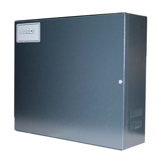
ALI50EN Auxiliary Power Supply
Certified
EN 54-4:1997+A1:2002+A2:2006
The Power Supply ALI50EN has been designed to be used as a Power Unit with power backup in Fire Alarm Systems, in conformity with
European manufacturer standards CPD 89/106/CEE.
Its mechanical and electrical features make it complying to EN 54-4: 2007 Standard (Fire Alarm detecting and signaling devices. Part 4 :
Power supply devices) which includes A1:2002 and A2:2006 updates.
The power supply unit is made by a switching power supply, limited in constant precision current (rectangular limitation), two 12V 17 Ah
batteries (not given within) digital and analogical control circuit and micro-controlled supervision circuit.
Power is available on 3 terminal-outputs protected by electronic fuses: A, B and C, for generic loads and one connection BATT (with
fuse): for back-up batteries. When a fuse trips, the corresponding LED on control board (see Fig.2, DL1, DL6, DL7, DL8) will turn ON.
Electronic fuses try periodically to restore the power output: if an overload is removed, the power will be available within 10 sec max.
The battery charge occurs at constant current (1A) until the battery voltage reaches its nominal value (27,6 V @ 25°C), with temperature
compensation. Maximum current supplied by the unit is 5A, where 4A is for charge and 1A is for recharging the battery.
Four LEDs show the loads current consumption (3 green and one red: DL2, DL3, DL4, DL5)
One LED shows the Mains presence (LED1)
Check of battery efficiency
The power supply periodically carries out the efficiency of the batteries:
At first activation of the power supply, the microprocessor will carry out the test of battery presence after about 20 seconds. If connected,
the test will be carried out every 10 minutes whilst in case it is not connected, it will continue carry out the test every 20 seconds showing
indication FAILURE.
During normal operation, the battery efficiency is checked by controlling the batteries voltage. If batteries do not manage to maintain an
acceptable voltage during test, there will be the indication FAILURE.
A test of the battery internal resistance is carried out within 15 seconds after the battery connection and then repeated every 2,5 hours, at
least (in conformity to attachment EN54-4/A2); if the internal resistance is over 1 ohm, there will be a FAILURE indication. With internal
resistance failure detected, this test is repeated every 5 minutes at most 5 times, to ensure recovery from spurious failure detection. It
will then be necessary to replace the batteries and check that terminals and fuses have a good electrical contact. When the battery is
replaced, the user should wait 15 seconds after battery connection, with presence of mains voltage, for the repetition of the test and
check if the failure is removed. It is possible repeat the test by pressing the button on the back of front panel display board for more than
2,5 seconds.
A microcontroller system controls various possible anomalies and gives a FAILURE indication in the following conditions:
1.
Output Fuses or Battery fuse interruptions
2.
Overloaded Battery (> 28V)
3.
Low Battery Voltage (< 20,8V)
4.
Mains power supply absence and no battery charge
5.
Disconnected Battery
Internal battery resistance >1 Ώ
6.
Failures are displayed on a frontal board; the detailed failure is showed on the internal power supply board.
In order to avoid that a possible failure in the regulator damages the charges or the battery, a protection circuit has been inserted against
over-Voltages, made of a SCR and a fuse. A fuse for mains alternated supplying is also present.
In case of failure in the power supply or of mains missing, the logic and control circuits are supplied by batteries.
S-326.1-ALI50EN-ENG A. 1 05-2015
Installation Manual
GENERAL FEATURES
FUNCTIONAL FEATURES
Page 1 of 7
Advertisement

Related Manuals for Honeywell NOTIFIER ALI50EN


Summary of Contents for Honeywell NOTIFIER ALI50EN
- Page 1 ALI50EN Auxiliary Power Supply Certified EN 54-4:1997+A1:2002+A2:2006 Installation Manual GENERAL FEATURES The Power Supply ALI50EN has been designed to be used as a Power Unit with power backup in Fire Alarm Systems, in conformity with European manufacturer standards CPD 89/106/CEE. Its mechanical and electrical features make it complying to EN 54-4: 2007 Standard (Fire Alarm detecting and signaling devices.
-
Page 2: Mechanical Specifications
ELECTRICAL SPECIFICATIONS Supplying Voltage 230 Vac +10% / -15% Ac mains frequency 50 Hz sinusoidal Current consumption by mains 1,1 A max. ( full load ) Output Voltage 27,6 Vdc ( -15% / +10%) Minimum output Voltage 20 Vdc at max charge, with mains absence and battery discharged Switching-off threshold Voltage 20 Vdc... - Page 3 1) Rotate the “screw in tie mounts” in vertical position and insert the tie. Do the same thing on the right side. SCREW IN TIE MOUNTS 2) Rotate the “screw in tie mounts” in horizontal position. Do the same thing on the right side. S-326.1-ALI50EN-ENG A.
- Page 4 3) Insert the belt in the central “screw in tie mounts”. Do the same thing on the right side. 4) Place the battery and then fix the belt. Do the same thing on the right side. S-326.1-ALI50EN-ENG A. 1 05-2015 Page 4 of 7...
- Page 5 Electrical connection Connect the power supply unit to the mains 230Vac by use of a differential magneto-thermic bipolar 6A switch (minimum distance between contacts 3mm) aimed to protect the line against possible short circuit and operator against current leakage. IMPORTANT :use different cables-passes and pipes for ac supplying input (mains 230 Vac) and dc outputs + alarms (SELV) – see Fig. 2 The minimum section recommended for ground connection is 1,5 mm.
-
Page 6: Control Board Leds
Output relay failure indication is active for: • Low battery (voltage lower than 20,8 Vdc) • Overcharged battery (voltage over 28 Vdc) • Disconnected battery • Battery internal resistance > 1 ohm • Faulty fuse START UP OF THE SYSTEM Even if not imperative, the following sequence of connection is suggested: Connect mains and ground to the concerned terminal AC1. -
Page 7: Cable Connection
F1 – Battery Fuse DL1, DL6, DL2, DL3, DL7, DL8: DL4, DL5: lights off = Loads FUSE1 – Fuse of Electronic Current the 230 Vac fuses level mains, not operating replaceable LED1: Mains presence To the To the To the Fig.2 remote battery...