Advertisement
Quick Links
INSTALLATION GUIDE
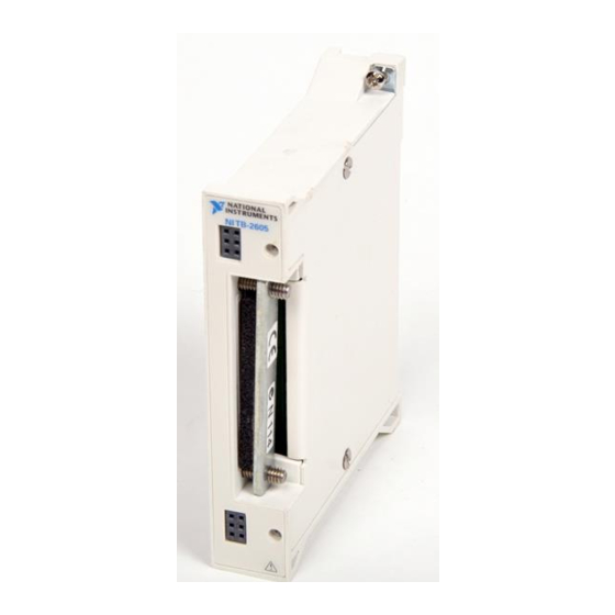
TB-2605 Isothermal Terminal Block
Contents
Introduction
This installation guide describes how to install and connect signals to the
TB-2605 isothermal terminal block for use with the NI 2501 and NI 2503
PXI switch cards.
Introduction ............................................................................................. 1
What You Need to Get Started ............................................................... 2
Signal Names .......................................................................................... 2
Signal Connection ................................................................................... 4
Installing Your Terminal Block .............................................................. 6
Installing the Analog Bus Plug ............................................................... 7
Cold-Junction Temperature Sensor......................................................... 9
Specifications .......................................................................................... 11
The TB-2605 is an isothermal terminal block that consists of a printed
circuit board with screw terminals. The terminal block connects directly
to the front panel I/O connector of the NI 2501 or NI 2503.
The terminal block can easily accommodate thermocouples, resistance
temperature detectors (RTDs), thermistors, and voltage signals.
The TB-2605 features an isothermal construction to minimize the
temperature gradients across the screw terminals and a high-accuracy
thermistor cold-junction temperature sensor for measuring with
thermocouples. Enclosures keep out air currents to maintain an isothermal
environment for the screw terminals and the cold-junction sensor.
Advertisement

Related Manuals for National Instruments TB-2605


Summary of Contents for National Instruments TB-2605
-
Page 1: Table Of Contents
INSTALLATION GUIDE TB-2605 Isothermal Terminal Block This installation guide describes how to install and connect signals to the TB-2605 isothermal terminal block for use with the NI 2501 and NI 2503 PXI switch cards. Contents Introduction ..................... 1 What You Need to Get Started ............... 2 Signal Names .................. -
Page 2: What You Need To Get Started
Use the screw terminals on the TB-2605 to make connections to all channels except the cold-junction sensor. The front side of the terminal block has two additional connectors for connecting to the analog bus. You can use the low-voltage AB plug to connect the analog bus of adjacent switch cards. - Page 3 CH40 CH44 CH12 CH16 CH20 CH35 CH31 CH27 CH11 CH26 CH30 CH34 CH10 CH25 CH29 CH33 CH24 CH28 CH32 1wireREF COM1- COM0- COM1+ COM0+ AB0+ AB1+ AB0- AB1- Figure 2. One-Wire Mode © National Instruments Corporation TB-2605 Isothermal Terminal Block...
-
Page 4: Signal Connection
Connect safety ground or shield wires to the chassis ground connection tab (7) using the provided solder lug (6). Tighten or replace the strain relief screws (10). Replace the terminal block cover (1) and tighten the cover screws (2). TB-2605 Isothermal Terminal Block ni.com... - Page 5 2 Cover Screws (captive) 6 Ground Solder Lug 9 Analog Bus Connectors 3 Strain Relief Bar 7 Chassis Ground Tab 10 Strain Relief Screws 4 Chassis Connection Screws Figure 4. TB-2605 Parts Locator Diagram © National Instruments Corporation TB-2605 Isothermal Terminal Block...
-
Page 6: Installing Your Terminal Block
NI 2501 or NI 2503 connector (the numbers in parentheses refer to items in Figure 5). The TB-2605 terminal block must be installed on the NI 2501/2503 switch card after Note the card is installed in the chassis. -
Page 7: Installing The Analog Bus Plug
3 Switch Card 2 Module Screws 4 Switch Card Connector Figure 5. Connecting the TB-2605 to the Switch Card Installing the Analog Bus Plug Refer to Figure 6 as you perform the following steps to install the analog bus plug. The cover should be attached to the terminal block before you connect the analog bus plug because the plug screws into the cover (the numbers in parentheses refer to items in Figure 6). - Page 8 The low-voltage analog bus plug can be used to connect the analog buses of adjacent switch cards, as shown in Figure 6. The signal connections for the analog bus are shown in Figure 7. TB-2605 Isothermal Terminal Block ni.com...
-
Page 9: Cold-Junction Temperature Sensor
Figure 7. Analog Bus Connector Cold-Junction Temperature Sensor The TB-2605 temperature sensor voltage output varies from 198.54 mV to 19.58 mV over the temperature range 0 to 55 °C, respectively, and has an accuracy of ±0.5 °C over the 15 to 35 °C temperature range and ±0.9 °C over the 0 to 15°... - Page 10 Use an average of a large number of samples to obtain the most accurate reading. Noisy environments require more samples for greater accuracy. Figure 8 shows the circuit diagram of the TB-2605 cold-junction temperature sensor. +5 V 4.7 k...
-
Page 11: Specifications
Includes the combined effects of the temperature sensor accuracy and the temperature difference between the temperature sensor and any screw terminal. The temperature sensor accuracy includes tolerances in all component values, the effects caused by temperature and loading, and self-heating. © National Instruments Corporation TB-2605 Isothermal Terminal Block... - Page 12 National Instruments, NI, ni.com, and LabVIEW are trademarks of National Instruments Corporation. Refer to the Terms of Use section on ni.com/legal for more information about National Instruments trademarks. Other product and company names mentioned herein are trademarks or trade names of their respective companies. For patents covering National Instruments products, refer to the appropriate location: Help»Patents in your software, the patents.txt file on your CD, or ni.com/patents.