
Related Manuals for Xerox WorkCentre PE114e


Summary of Contents for Xerox WorkCentre PE114e
-
Page 1: Table Of Contents
WorkCentre PE114e SERVICE Manual DIGITAL LASER MFP CONTENTS 1. Precautions 2. Reference Information 3. Specifications 4. Summary of product 5. Disassembly and Reassembly 6. Alignment and Adjustments 7. Troubleshooting 8. Exploded Views and Parts List 9. Block Diagram 10. Connection Diagram... - Page 2 Service Manual...
-
Page 3: Precautions
Precautions 1. Precautions In order to prevent accidents and to prevent damage to the equipment please read the precautions listed below carefully before servicing the printer and follow them closely. 1.1 Safety Warning (1) Only to be serviced by appropriately qualified service engineers. High voltages and lasers inside this product are dangerous. - Page 4 Precautions 1.2 Caution for safety 1.2.1 Toxic material This product contains toxic materials that could cause illness if ingested. (1) If the LCD control panel is damaged it is possible for the liquid inside to leak. This liquid is toxic. Contact with the skin should be avoided, wash any splashes from eyes or skin immediately and contact your doctor.
- Page 5 Precautions 1.2.3 Handling Precautions The following instructions are for your own personal safety, to avoid injury and so as not to damage the printer (1) Ensure the printer is installed on a level surface, capable of supporting its weight. Failure to do so could cause the printer to tip or fall.
- Page 6 Precautions 1.2.5 Disregarding this warning may cause bodily injury (1) Take care - some parts may be hot. The fuser unit works at a high temperature. Use caution when working on the printer. Wait for the fuser to cool down before disassembly. (2) Take care not to trap fingers or hair.
- Page 7 Precautions 1.3 ESD Precautions Certain semiconductor devices can be easily damaged by static electricity. Such components are commonly called “Electrostatically Sensitive (ES) Devices”, or ESDs. Examples of typical ESDs are: integrated circuits, some field effect transistors, and semiconductor “chip” components. The techniques outlined below should be followed to help reduce the incidence of component damage caused by static electricity.
- Page 8 Precautions MEMO Service Manual...
-
Page 9: Reference Information
Reference Information 2. Reference Information This chapter contains the tools list, list of abbreviations used in this manual, and a guide to the location space required when installing the printer. A definition of tests pages is also included. 2.1 Tool for Troubleshooting The following tools are recommended for safe and smooth troubleshooting described in this service manual. - Page 10 Reference Information 2.2 Acronyms and Abbreviations The table in the below explains abbreviations used in this service manual. The contents of this service manual are declared with abbreviations in many parts. Please refer to the table. Analog-to-Digital-Conversion FCOT First Copy Out Time Access Point FLexiable FLat Cable Alternating Current...
- Page 11 Reference Information Inter Process Communication Random Access Memory Images Per Minute Read Only Memory Liquid Crystal Display SCF/SCT Second Cassette Feeder/Second Cassette Tray Light Emitting Diode SMPS Switching Mode Power Supply Laser Scanning Unit SPGP Samsung Printer Graphic Megabyte Processor Multi-Functional Product Samsung Printer Language Megahertz...
- Page 12 Reference Information 2.3 Select a location for the printer • Leave enough room to open the printer trays, covers, and allow for proper ventilation. (see diagram below) • Provide the proper environment : - A firm, level surface - Away from the direct airflow of air conditioners, heaters, or ventilators - Free of extreme fluctuations of temperature, sunlight, or humidity - Clean, dry, and free of dust Service Manual...
- Page 13 Reference Information 2.4 The Sample Pattern for the Test The sample pattern shown in below is the standard pattern used in a factory. The contents of the life span and the printing speed are measured with the pattern shown in below. (The picture in the manual is 70% size of the actual A4 size.) 2.4.1 A4 5% Pattern Service Manual...
- Page 14 Reference Information 2.4.2 A4 2% Pattern Service Manual...
- Page 15 Reference Information 2.4.3 A4 IDC 5% Patten Service Manual...
- Page 16 Reference Information MEMO Service Manual...
-
Page 17: Specifications
Specifications 3. Specifications Specfications are correct at the time of printing. Product specifications are subject to change without notice. See below for product specifications. 3.1 General Specifications Items SCX-4100 Remarks General Major Features Copier,Print,Scan Size (W*D*H) 16.6"x15.8" x9.4" (422x400x239mm) Net Weight(Inc. Toner Cartridge) 0.69 Kg Net Weight(exc. - Page 18 Specifications 3.2 Print Specification Items SCX-4100 Remarks PRINT Print Speed 15ppm/Ltr, 14ppm/A4 Print Method Laser Print Language Power Save Yes(5/10/15/30/45min.) Resolution Normal 600 x 600 dpi Toner Save LCD Only (Toner Save On/Off Setting method is in the Menu). Memory FPOT From Stand by Approx.
- Page 19 Specifications 3.4 Copy Specification Items SCX-4100 Remarks COPY Copy Quality Selection or Text 600x300dpi Original Image type Text/Photo 600x300dpi selection Mode Photo 600x600dpi for Platen FCOT Stand by Approx. 12 seconds From Cold Status Less than 54 seconds Copy Speed / Letter SDMC at all mode 15cpm/Ltr.
- Page 20 Specifications 3.5 Paper Handiling Specification Items SCX-4100 Remarks Paper Handling Capacity( 20lbs) Main Tray 250sheets Bypass(MP Tray) Single Sheet Optional Cassette Output Capacity Face Down: 50Sheets/20lb Face Up: 1Sheet Output Control Face down/Face up Paper Size Main Tray Legal,A4,Letter, Folio, Executive, B5, A5, A6 Bypass Bypass:Envelope6 3/4, 7...
- Page 21 Specifications 3.6 Other Specification Items SCX-4100 Remarks Software WHQL Win 3.x Win 95 Win 98&WinME Win NT 4.0 Win 2000 Win XP Mac Printer Only Linux Print, Scan Printer Printer driver only for WinXP Scanner Driver Printer Package TWAIN Remote Control Panel, Only for upgrade FW PC-FAX...
- Page 22 Specifications MEMO Service Manual...
-
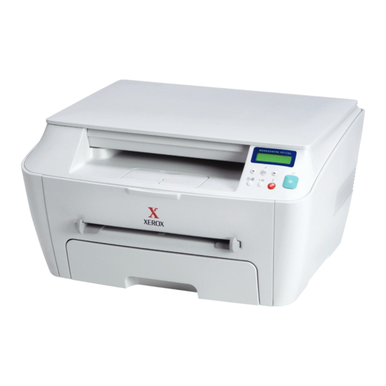
Page 23: Summary Of Product
Summary of product 4. Summary of Product This chapter describes the functions and operating principles of the main component. 4.1 Printer Components 4.1.1 Front View Service Manual... - Page 24 Summary of Product 4.1.2 Rear View Service Manual...
- Page 25 Summary of product 4.1.3 Control Panel Service Manual...
- Page 26 Summary of Product 4.2 System Layout SCAN PART Service Manual...
- Page 27 Summary of product 4.2.1 Paper Feed Mechanism The printer has a universal cassette which automatically loads paper and a manual feed which supplies paper single sheet at a time. The cassette has a friction pad which separates paper to ensure single sheet feeding, and it has a sensor, which checks when the paper tray is empty.
- Page 28 Summary of Product 4.2.4.5 Safety Relevant Facts • To prevent overheating - 1st protection device: Hardware cuts off when overheated - 2nd protection device: Software cuts off when overheated - 3rd protection device: Thermostat cuts off mains power to the lamp. •...
- Page 29 Summary of product 4.2.6 LSU (Laser Scanner Unit) This is the core of the laser printer. It converts the video data received from the computer into an electrostatic latent image on the surface of the OPC drum. This is achieved by controlling the laser beam and exposing the surface of the OPC drum to the laser light.
- Page 30 Summary of Product 4.2.7 Toner Cartridge The toner cartridge is an integral unit containing the OPC unit and toner unit. The OPC unit consists of the OPC drum and charging roller, and the toner cartridge unit consists of the toner, supply roller, developing roller, and blade (Doctor blade) - Developing Method: Non magnetic 1 element contacting method - Toner: Non magnetic 1 element shatter type toner...
- Page 31 Summary of product 4.3 Main PBA The Engine Board and Controller Board have been integrated into a single PBA. This consists of the CPU, printer scanner and line control functions. The CPU functions as the bus controller, I/O handler, motor driver and PC inter-face. The main board sends the Current Image Video data to the LSU and manages the Electrophotographic printing process.
- Page 32 Summary of Product 4.3.1 ASIC (Chorus2) The Chorus2 (16Bit RISC Processor) ASIC is the main processor controlling the whole system. It controls all of the printing and scanning functions using a system program stored in flash memory. •Main function block •...
- Page 33 Summary of product 3) Paper Feeding, Toner Cartridge Sensing When paper passes the actuator on the feed sensor, it is detected by the Photo interrupter. Signal (nP_FEED, PIN 186) monitored by the CPU and this signal starts the process of creating the image after certain delay time If the feed sensor is not detected within 1 sec.
- Page 34 Summary of Product 4.4 SMPS & HVPS The SMPS and HVPS are on one integrated board. The SMPS supplies the DC power to the system. It takes either 110V or 220V and outputs the +5V and 24V supplies to the main and other PBAs. The HVPS creates the high voltage of THV/MHV/Supply/Dev and supplies it to the toner cartridge.
- Page 35 Summary of product 4.4.1 HVPS(High Voltage Power Supply) 1) Transfer High Voltage (THV+) - Function : It is this voltage that transfers toner from the OPC Drum to the paper. - Output voltage : Maximum +5000V ±5% (no load, variable duty cycle) - Error : IF THV (+) is not present, low density printing occurs due to toner on the OPC Drum not being transferred to the paper.
- Page 36 Summary of Product 4.4.2 SMPS (Switching Mode Power Supply) This is the power source for the whole system. It is an independent module so that it is possible to use it for common use. It is mounted at the bottom of the set. It consists of the SMPS section, which supplies the DC power to drive the system, and the AC heater control part, which supplies the power to the fuser.
- Page 37 Summary of product 6) Feature - Insulation resistance : over 50M Ω (at DC500V) - Insulation retest pressure : Must be no problem within 1min. (at 1500Vzc, 10mA) - Leakage voltage : under 3.5mA - Running voltage : under 40A peak (at 25°c, Cold start) Under 60A peak (in other conditions) - Rise Time : Within 2Sec - Fall Time : Over 20ms - Surge : Ring Wave 6KV-500A (Normal, Common)
- Page 38 Summary of Product 4.5 Engine F/W 4.5.1 Feeding If feeding from the cassette the drive of the pickup roller is controlled by controlling the pick-up solenoid. The on/off of the solenoid is controlled by controlling the general output port or the external output port. If feeding from the manual feeder the set decides to feed the paper according to the operation of the manual sensor, and by driving the main motor, insert the paper in front of the feed sensor.
- Page 39 Summary of product 4.5.4 Fusing The temperature of the heat roller's surface is detected according to the resistance value of the thermistor. The thermistor resistance is measured using the A/D converter and thus the CPU can determine the temperature of the heat roller.
- Page 40 Summary of Product MEMO Service Manual 4-18...
-
Page 41: Disassembly And Reassembly
Disassembly and Reassembly 5. Disassembly and Reassembly 5.1 General Precautions on Disassembly When you disassemble and reassemble compo- Releasing Plastic Latches nents, you must use extreme caution. The close proximity of cables to moving parts makes proper Many of the parts are held in place with plastic routing a must. - Page 42 Disassembly and Reassembly 5.2 Front and Rear Cover Units 1. Take the Cassette out of the printer. 3. Remove the 4 screws securing the Rear Cover and remove it, as shown below. Rear Cover Cassette 2. Remove the Front Cover in the direction of arrow. Service Manual...
- Page 43 Disassembly and Reassembly 5.3 Side Covers 1. Before you remove the Side Cover(Left Cover, Right 3. Remove 1 screw at the front of the unit. Unclip the Cover), you should remove: right cover along the top edge and remove it from the -Rear Cover (see page 5-2) Frame Assembly.
- Page 44 Disassembly and Reassembly 5.4 Scanner Ass’y < Caution > 1. Before disassembling the Scanner Ass'y first lift 2. Take care not to trap your fingers or hand in the it carefully at the front edge. The support lever mechanism. will automatically raise into position. 5.4.1 Remove Scanner Ass’y 1.
- Page 45 Disassembly and Reassembly 5.4.2 Dismantle Scanner Ass’y < Caution > 1. Before disassembling the scanner module remove the 2 plastic spacers from each end of the scanner module. 1. Lift the Platen Cover upward and remove it. 3. Remove the CCD Cable, as shown below. FFC Cable Platen Cover 2.
- Page 46 Disassembly and Reassembly 4. Pull up the CCD Shaft and take out the Scanner 6. Remove the Pulley Idle, as shown below. Module. Pulley Idle Spring Scanner Module ETC Belt Pulley Bracket CIS Shaft 7. Remove the 2 screws and take out the Scan Motor Ass'y.
- Page 47 Disassembly and Reassembly 5.5 Middle Cover 1. Disconnect the OPE harness from the Main PBA and 2. Remove the 4 screws securing the OPE Unit from the remove the 4 screws securing the Middle Cover. Middle Cover. Remove it, as shown below. Middle Cover OPE Unit OPE Harness...
- Page 48 Disassembly and Reassembly 5.6 Fuser(Heat Lamp Type) 1. Before you remove the Fuser, you should remove: 4. Remove 2 screws and take the Halogen Lamp out of -Rear Cover (see page 5-2) the Heat Roller. 2. Unplug two connectors from the boards and then remove 4 screws.
- Page 49 Disassembly and Reassembly 6. Remove 4 screws and divide the Fuser into two parts. 8. Remove the Thermister from the Fuser Cover. Fuser Cover Thermister 7. Unwrap the Thermistor Harness, as shown below. Thermister Harness Service Manual...
- Page 50 Disassembly and Reassembly 5.7 Exit Roller 1. Before you remove the Exit Roller you should remove: 2. Remove the white Exit Gear, and release a bearing - Rear Cover (see page 5-2) clip at one end then remove the shaft and rollers as - Side Covers (see page 5-3) shown below.
- Page 51 Disassembly and Reassembly 5.9 Fan 1. Before you remove the Fan you should remove: 2. Unplug the connector from the SMPS and remove 1 - Rear Cover (see page 5-2) screw. Then take out the Fan. - Right Side Cover (see page 5-3) DC Fan 5.10 Drive Ass’y 1.
- Page 52 Disassembly and Reassembly 5.11 Engine Shield Ass’y 1. Before you remove the Fuser, you should remove: 2. Remove the 14 screws securing the Engine Shield - Rear Cover (see page 5-2) Ass'y and unplug the all connectors. Then remove the - Side Covers (see page 5-3) Engine Shield Ass'y.
- Page 53 Disassembly and Reassembly 5.13 SMPS 1. Before you remove the SMPS, you should remove: 4. Remove 3 screws and take the SMPS out. - Rear Cover (see page 5-2) - Side Covers (see page 5-3) SMPS - Fuser Connector (see page 5-7) - Engine Shield Ass'y (see page 5-11) 2.
- Page 54 Disassembly and Reassembly 5.14 Transfer Roller 1. Before you remove the Transfer Roller you should 4. Unlatch the Bush and remove it. Then lift the Transfer remove: Roller out, as shown below. - Rear Cover (see page 5-2) Transfer - Side Covers (see page 5-3) Roller - Scanner Ass’y (see page 5-4) - Middle Cover (see page 5-6)
- Page 55 Disassembly and Reassembly 5.15 Feed Roller 1. Before you remove the Feed Roller you should 4. Remove 3 screws from the Feed Bracket and take it out. remove: - Rear Cover (see page 5-2) Feed Bracket - Side Covers (see page 5-3) - Scanner Ass’y (see page 5-4) - Middle Cover (see page 5-6) - LSU (see page 5-9)
- Page 56 Disassembly and Reassembly 7. Remove the Feed Roller and Feed Roller1, as shown below. Feed Roller Feed Roller1 Service Manual 5-16...
- Page 57 Disassembly and Reassembly 5.16 Pick Up Roller & Solenoid 1. Before you remove the Pick Up Roller and Solenoid 4. Remove 2 screws then remove the Regi Solenoid and you should remove: Pick Up Solenoid. - Rear Cover (see page 5-2) - Side Covers (see page 5-3) - Scanner Ass’y (see page 5-4) - Middle Cover (see page 5-6)
- Page 58 Disassembly and Reassembly MEMO Service Manual 5-18...
-
Page 59: Alignment And Adjustments
Alignment & Adjustments 6. Alignment and Adjustments This chapter describes some of the main service procedures including: Using the EDC mode; Clearing paper jam and test patterns. Much of this chapter is also included in the user's guide. 6.1 Engine Test Mode The Engine Tests Mode supplies useful functions to check the condition of the engine. - Page 60 Alignment & Adjustments 6.2 Paper Path SCAN PART L S U L S U L S U Fuser Toner Cartridge Fuser Toner Cartridge Fuser Toner Cartridge EXIT Sensor EXIT EXIT Sensor MP Sensor Sensor Feed Sensor MP Sensor MP Sensor Feed Feed Sensor...
- Page 61 Alignment & Adjustments 6.3 Clearing Paper Jams When a paper jam occurs, "Paper Jam" appears on the display. Refer to the table below to locate and clear the paper jam. Message Location of Jam PAPER JAM 0 OPEN/CLOSE DOOR In the paper tray PAPER JAM 1 OPEN/CLOSE DOOR In the paper exit area PAPER JAM 2 CHECK INSIDE...
- Page 62 Alignment & Adjustments 6.3.2 In the Paper Exit Area 1 Open and close the front cover. The jammed paper 6 Open the rear cover. is automatically ejected from the machine. If the paper is not ejected continue to step 2. 7 Remove the jammed paper by gently pulling it straight out.
- Page 63 Alignment & Adjustments 6.3.3 In the Fuser Area or Around the Toner Cartridge NOTE: The fuser area is hot. Take care when removing 2 Remove the jammed paper by gently pulling it paper from the machine. straight out. 1 Open the front cover and lightly push down on the cartridge then pull to take it out.
- Page 64 Alignment & Adjustments 6.4 Printing the System Data List Your machine can print the system data report which shows the status of the user-selectable options. You may print this list to confirm your changes after changing any settings. To print the system data list: 1 Press Menu/Exit until "Report"...
- Page 65 Alignment & Adjustments 6.7 Consumables and Replacement Parts The cycle period outlined below is a general guideline for maintenance. The example list is for an average usage of 50 transmitted and received documents per day. Environmental conditions and actual use will vary these factors. The cycle period given below is for reference only.
- Page 66 Alignment & Adjustments 6.9 Periodic Defective Image If a mark or other printing defect occurs at regular intervals down the page it may be caused by a damaged or contaminated roller. Measure the repetition interval and refer to the table below to identify the roller concerned. Roller Defective image Typical defect...
-
Page 67: Troubleshooting
Troubleshooting 7. Troubleshooting 7.1 Printing Problems – Causes and Solutions 7.1.1 Vertical Black Lines and Bands 1. Straight thin black vertical lines occur in the printing. • Description 2. Dark black vertical bands occur in the printing. Check and Cause Solution Digital Printer 1. - Page 68 Troubleshooting 7.1.3 Horizontal Black Bands 1. Dark or blurry horizontal stripes occur in the printing periodically. • Description (These may occur at regular intervals down the page.) Check and Cause Solution Digital Printer 1. Bad contacts on the toner cartridge high 1.
- Page 69 Troubleshooting 7.1.5 Light Image • Description The printed image is light, with no ghost. Check and Cause Solution Digital Printer 1. Toner Save mode enabled 1. Ensure the Toner Save mode is off. Check Digital Printer set and driver settings. Digital Printer 2.
- Page 70 Troubleshooting 7.1.7 Uneven Density • Description Print density is uneven between left and right. Check and Cause Solution 1. The pressure force on the left and right 1. Replace both the left and right bush and springs of the transfer roller is not even, spring assemblies.
- Page 71 Troubleshooting 7.1.9 Ghost (1) • Description Ghost occurs at 75.5 mm intervals of the OPC drum in the whole printing. Check and Cause Solution Digital Printer 1. Bad contacts caused by contamination 1 and 2. Clean all HV contacts, If problem Digital Printer from toner particles between high voltage persists replace the HVPS.
- Page 72 Troubleshooting 7.1.11 Ghost (3) • Description Ghost occurs at 57 mm intervals. Check and Cause Solution Digital Printer Digital Printer Fuser contamination. 1. Disassemble the fuser and remove any contamination on the rollers. Clean any Digital Printer Digital Printer contamination from between the Thermistor and the Heat roller.
- Page 73 Troubleshooting 7.1.14 Stains on Back of Page • Description The back of the page is stained at 46.5 or 58.7 mm intervals. Check and Cause Solution Digital 1. 46.5mm : Transfer roller is contaminated. 1. Perform the OPC Cleaning Mode Print 2 or Digital Pri 3 times.
- Page 74 Troubleshooting 7.2 Copy Problems 7.2.1 White Copy • Description Blank page is printed out when copying. Check and Cause Solution 1. Check the Scanner Cover is properly closed. 1. Room light can pass through a thin original. 2. Check shading profile. 2.
- Page 75 Troubleshooting 7.2.3 Abnormal noise • Description There is noise from the ADF when copying. Check and Cause Solution 1. Check the Scanner Motor, gearbox and rollers. 1. Check for correct assembly of gears and motor. Ensure no parts are fouling and there are no foreign objects in the mechanism or scanner path.
- Page 76 Troubleshooting 7.3 Paper Feed problems – Causes and Solutions 7.3.1 Wrong Print Position • Description Printing begins at wrong position on the paper. Check and Cause Solution Wrong sensor timing caused by defective feed sensor Replace the defective actuator actuator. 7.3.2 JAM 0 1.
- Page 77 Troubleshooting 7.3.3 JAM 1 1. Paper is jammed in front of or inside the fuser. • Description 2. Paper is stuck in the exit roller and in the fuser just after passing through the Actuator-Feed. Check and Cause Solution L S U 1.
- Page 78 Troubleshooting 7.3.5 Multi-Feeding • Description Multiple sheets of paper are fed at once. Check and Cause Solution 1. Check that the paper size guides are set correctly 1. Adjust paper guides. (cassette and MPF tray). 2. Solenoid malfunction (the solenoid does not work 2.
- Page 79 Troubleshooting 7.3.7 Paper rolled on the OPC Drum • Description Paper is rolled up in the OPC. Check and Cause Solution 1. Paper is too thin. 1. Use paper that conforms to the printer specification. 2. The face of paper is curled. 2.
- Page 80 Troubleshooting 7.4 Printer Faults – Causes and Solutions 7.4.1 Fuser Error • Description A message "Open Heat Error/Over heat/Heating Error' is displayed in the LCD panel. Check and Cause Solution 1. Thermostat, fuser power cable or heat lamp is 1. Replace the whole fuser assembly if the open circuit.
- Page 81 Troubleshooting 7.4.3 Fuser gear melts due to overheating causing Paper Jam. Constant Jam where paper is entering Fuser unit. • Description Fuser rollers do not turn Check and Cause Solution 1. Check the Heat Lamp, thermostat and thermistor 1. Use EDC Mode to test the fuser. Replace Fuser unit Replace SMPS or Main PBA as appropriate.
- Page 82 Troubleshooting 7.4.5 Paper Empty without indication • Description The paper empty message does not appear in the LCD when the paper cassette is empty. Check and Cause Solution 1. Deformed paper sensor actuator or faulty sensor. 1. Replace the defective actuator. 2.
- Page 83 Troubleshooting 7.4.7 No error message when the cover is open • Description The Cover Open message does not appears on the LCD even when the print cover is open. Check and Cause Solution 1. The ‘Open Cover’ microswitch may be stuck or faulty 1.
- Page 84 Troubleshooting 7.4.8 Defective motor operation • Description Main motor is faulty and paper does not feed into the printer, resulting in Jam 0' Check and Cause Solution 1. The main motor harness or Motor PCB may be faulty. 1. Check the motor harnesses and connectors, replace if defective..
- Page 85 Troubleshooting 7.4.10 Printed Vertical Lines become curved • Description When printing, vertical lines are not straight. Check and Cause Solution 1. Check stability of 24V supply to LSU. 1. 24V stable - Replace LSU. 24V unstable replace SMPS, if the problem persists replace the main PBA.
- Page 86 Troubleshooting 7.5 Toner Cartridge Service Only toner cartridges supplied by Samsung should be used. Printing defects or set damage caused by the use of non-approved toner cartridges or un-licensed toner refills are not covered by the guarantee. 7.5.1 Precautions on Safe-keeping of Toner Cartridge Excessive exposure to direct light for more than a few minutes may cause damage to the cartridge.
- Page 87 Troubleshooting 7.5.4 Signs and Measures of Poor toner cartridge Fault Signs Cause & Check Solution Light image and • The printed image 1. If the image is light or dirty 1. All of 1, 2, 3 partially blank is light or dirty and and untidy - Shake the toner If image quality improves by image...
- Page 88 Troubleshooting Fault Signs Cause & Check Solution 1. If light or dark black dots White Black spot • Light or dark black 1. For item 1 - occur at regular intervals this dots on the image Run OPC Cleaning Mode Print is because the toner cartridge occur periodically.
- Page 89 Troubleshooting Fault Signs Cause & Check Solution Ghost & Image • The printed image 1. The printed image is too light 1. All of Items 1, 2, 3 Contamination is too light or dark, or dark, or partially (a) Clean the contacts on the or partially contaminated black.
- Page 90 Troubleshooting 7.6 Software Problems – Causes and Solutions 7.6.1 The printer is not working (1) • Description While Power turned on, the printer is not working in the printing mode. Check and Cause Solution 1. Run Self-Test Mode: using the menu buttons print the 1.
- Page 91 Troubleshooting 7.6.2 The printer is not working (2) After receiving the print command there is no response at all or print speed is low • Description due to wrong setup of the environment rather than malfunction of the printer itself. Check and Cause Solution 1.
- Page 92 Troubleshooting 7.6.3 Abnormal Printing Printing does not work – even after replacing the cable • Description Printer does not work at all or strange fonts are printed, Check and Cause Solution 1. Set up the parallel port using CMOS SETUP. 1.
- Page 93 Troubleshooting 7.6.4 SPOOL Error SPOOL (simultaneous peripheral operations online) is the process Windows uses to • Description manage print jobs. Jobs are processed and then stored on the hard disk until the printer is ready to accept them Check and Cause Solution 1.
- Page 94 Troubleshooting MEMO Service Manual 7-28...
-
Page 95: Exploded Views And Parts List
Exploded View & Parts List 8. Exploded Views and Parts List Up-date On August. 17. 2004 SEC CODE : SCX-4100/XRX, SCX-4100/XRH 8.1 Main Assembly ......... . page(8-2) 8.2 Frame Assembly . -
Page 96: Main Assembly
Exploded View & Parts List 8.1 Main Assembly Frame Toner Cartridge Service Manual... - Page 97 EXPLODED VIEW & PARTS LIST Main Assembly Parts List SA : Service Available O : Service available X : Service not available Description SEC.Code Q’ty Remark SCX-4100/XRX SCX-4100/XRH MEA UNIT-COVER MIDDLE JC97-01958E SCX-4100 MEA UNIT-COVER REAR JC97-01959B SCX-4100 COVER-M_REAR JC63-00475B COVER-M_REAR DOOR JC63-00476B COVER-M_SIDE_L...
-
Page 98: Frame Assembly
Exploded View & Parts List 8.2 Frame Assembly Service Manual... - Page 99 Exploded View & Parts List Frame Unit Assembly Parts List SA : Service Available O : Service available X : Service not available Description SEC.Code Q’ty Remark ELA UNIT-FRAME LOWER, 110V JC96-03137A 110V ELA UNIT-FRAME LOWER, 220V JC96-03137B 220V FRAME-M-BASE JC61-00579A GUIDE-P-PAPER JC61-00943A...
- Page 100 Exploded View & Parts List Frame Unit Assembly Parts List(Cont.) SA : Service Available O : Service available X : Service not available Description SEC.Code Q’ty Remark IPR-P-GROUND_FUSER JC70-00310A SHAFT-FEED IDLE JC66-00527A BUSH-M-FEED IDLE JC61-00585A SPRING ETC-TR JC61-70958A Spring Feed Idle IPR-P_GROUND_DRIVE2 JC70-00335A SPRING-TS...
-
Page 101: Scanner Unit Assembly
Exploded View & Parts List 8.3 Scanner Unit Assembly Service Manual... - Page 102 Exploded View & Parts List Scanner Unit Assembly Parts List SA : Service Available O : Service available X : Service not available Description SEC.Code Q’ty Remark UNIT SCAN JC96-03136B SCX-4100 COVER-M-PLATEN JC63-00454B SHEET-WHITE SPONGE JC63-00209A HINGE PIVOT JC61-00929A COVER-M-SCAN UPPER JC63-00452B GLASS SCAN JC01-00002A...
-
Page 103: Fuser Unit Assembly
Exploded View & Parts List 8.4 Fuser Unit Assembly Service Manual... - Page 104 Exploded View & Parts List Fuser Unit Assembly Parts List SA : Service Available O : Service available X : Service not available Description SEC.Code Q’ty Remark ELA HOU-FUSER_220V JC96-03135B 220V ELA HOU-FUSER_110V JC96-03135A 110V COVER-M-FUSER JC63-00478A HOLDER-M-PLATE CLAW JC61-00584A SPRING ETC-CLAW JC61-00064A PMO-ROLLER EXIT...
- Page 105 Exploded View & Parts List Fuser Unit Assembly Parts List SA : Service Available O : Service available X : Service not available Description SEC.Code Q’ty Remark WASHER-PLAIN 6031-001051 LABEL(R)-HV FUSER JC68-00407A SCREW-TAPTITE 6006-001078 SCREW-MACHINE 6006-001193 SCREW-TAPTITE 6603-000269 SCREW-TAPTITE 6003-000196 Service Manual 8-11...
-
Page 106: Middle Cover Unit Assembly
Exploded View & Parts List 8.5 Middle Cover Unit Assembly Service Manual 8-12... - Page 107 Exploded View & Parts List Middle Cover Unit Assembly Parts List SA : Service Available O : Service available X : Service not available Description SEC.Code Q’ty Remark MEA UNIT-COVER MIDDLE JC97-01958E COVER-M_MIDDLE JC63-00473E PMO-STACKER JC72-01340B STOPPER-M-LEVER JC61-00949A SPRING ETC-TS-CHARGE APOLLO JC61-00026A PMO-SUB_M_STACKER JC72-01343A...
- Page 108 Exploded View & Parts List 8.6 Drive Unit Assembly HARNESS-MOTOR Drive Unit Assembly Parts List SA : Service Available O : Service available X : Service not available Description SEC.Code Q’ty Remark ELA UNIT-DRIVE JC96-03138A BRACKET-P-GEAR 1400 JC61-00598A GEAR-RDCN 53/26 JC66-00388A GEAR-RDCN 113/33 JC66-00391A...
-
Page 109: Cassette Unit Assembly
Exploded View & Parts List 8.7 Cassette Unit Assembly Service Manual 8-15... - Page 110 Exploded View & Parts List Cassette Unit Assembly Parts List SA : Service Available O : Service available X : Service not available Description SEC.Code Q’ty Remark MEA UNIT-CASSETTE_MB JC97-01914B ADJUST-M-CASSETTE_L JC70-00300D ADJUST-M-CASSETTE_R JC70-00301D GEAR-PINION JG66-40003A IPR-PLATE PAD JC70-00314A RPR-FRICTION PAD JC73-00140A SHEET-HOLDER PAD JC63-00290A...
-
Page 111: Block Diagram
Block Diagram 9. Block Diagram Service Manual... - Page 112 Block Diagram MEMO Service Manual...
-
Page 113: Connection Diagram
Connection Diagram 10. Connection Diagram Service Manual 10-1...