Table of Contents
Advertisement
Quick Links
TECHNICAL MANUAL
Of
Intel H310 Express Chipset
Based Mini-ITX M/B
NO. G03-NC8H-F
Revision: 3.0
Release date: March 5, 2020
Trademark:
* Specifications and Information contained in this documentation are furnished for information use only, and are
subject to change at any time without notice, and should not be construed as a commitment by manufacturer.
Advertisement
Table of Contents

Related Manuals for JETWAY NC8H


Summary of Contents for JETWAY NC8H
- Page 1 TECHNICAL MANUAL Intel H310 Express Chipset Based Mini-ITX M/B NO. G03-NC8H-F Revision: 3.0 Release date: March 5, 2020 Trademark: * Specifications and Information contained in this documentation are furnished for information use only, and are subject to change at any time without notice, and should not be construed as a commitment by manufacturer.
- Page 2 Environmental Protection Announcement Do not dispose this electronic device into the trash while discarding. To minimize pollution and ensure environment protection of mother earth, please recycle.
-
Page 3: Table Of Contents
TABLE OF CONTENT ENVIRONMENTAL SAFETY INSTRUCTION ..............iii USER’S NOTICE ........................iv MANUAL REVISION INFORMATION ..................iv ITEM CHECKLIST ........................iv CHAPTER 1 INTRODUCTION OF THE MOTHERBOARD FEATURE OF MOTHERBOARD ................1 SPECIFICATION ......................2 LAYOUT DIAGRAM ....................3 CHAPTER 2 HARDWARE INSTALLATION JUMPER SETTING .....................7 CONNECTORS, HEADERS AND WAFERS ..............11 2-2-1 CONNECTORS .....................11 2-2-2... -
Page 4: Environmental Safety Instruction
Environmental Safety Instruction Avoid the dusty, humidity and temperature extremes. Do not place the product in any area where it may become wet. 0 to 40 centigrade is the suitable temperature. (The temperature comes from the request of the chassis and thermal solution) ... -
Page 5: User's Notice
USER’S NOTICE COPYRIGHT OF THIS MANUAL BELONGS TO THE MANUFACTURER. NO PART OF THIS MANUAL, INCLUDING THE PRODUCTS AND SOFTWARE DESCRIBED IN IT MAY BE REPRODUCED, TRANSMITTED OR TRANSLATED INTO ANY LANGUAGE IN ANY FORM OR BY ANY MEANS WITHOUT WRITTEN PERMISSION OF THE MANUFACTURER. -
Page 6: Chapter 1 Introduction Of The Motherboard
Chapter 1 Introduction of the Motherboard 1-1 Feature of Motherboard Intel ® H310 express chipset LGA 1151 CPU socket supports Intel ® Coffee Lake-S series processor (TDP﹤65 Support DC 12~24V Input Support 2* DDR4 2133/2400/2666MHz SO-DIMM up to 32GB ... -
Page 7: Specification
1-2 Specification Spec Description Thin mini-ITX form factor; PCB size: 17.0x17.0cm Design Intel H310 Express Chipset Chipset Intel ® LGA 1151 Socket for Coffee Lake-S series processors CPU Socket * for detailed CPU support information please visit our website 2*DDR4 SO-DIMM slot ... -
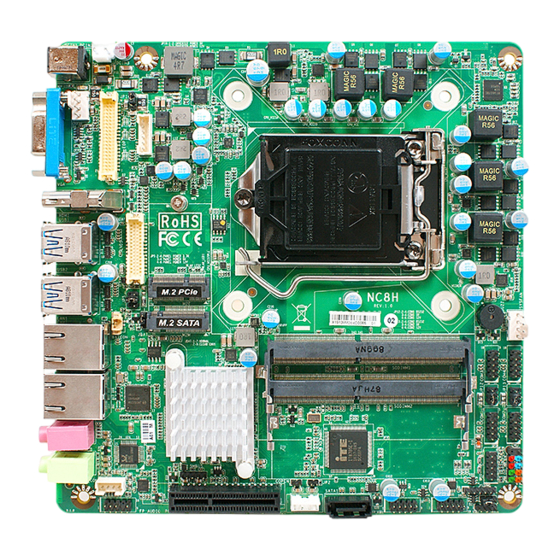
Page 8: Layout Diagram
1* Front panel header 2* 9-Pin USB 2.0 header for 4* USB 2.0 ports 1* 4-Pin USB 2.0 header for 1* USB 2.0 port 1* PS/2 keyboard & mouse header 1* SMBUS header 1*Front panel audio header ... - Page 9 Internal 12V~24V DC-IN Power Connector 12V~24V DC-IN CPUFAN Power Jack Connector LGA 1151 CPU Socket LVDS VGA Port INVERTER EDP Wafer LVDS Wafer HDMI Port M.2E-Key Slot (M2E) USB 3.0 Ports M.2 M-Key Slot SYSFAN (M2M) Connector H310 Chipset RJ-45 LAN Ports Serial Port Headers...
- Page 10 JP16 JBAT JP13 COPEN JP12 JAT_ATX Connectors...
- Page 11 Name DCIN1 12V~24V DC–in Power Jack VGA Port Connector HDMI HDMI Port Connector USB1/USB2 USB 3.0 Port Connector X4 LAN1/ LAN 2 RJ-45 LAN Connector X2 HMIC Audio MIC Connector HOUT Audio Line-out Connector DCIN3 Internal 12V~24V DC–in Power Connector SATA1 SATAIII Connector PWROUT...
-
Page 12: Chapter 2 Hardware Installation
Jumper Name Description JBAT Clear CMOS RAM Settings 3-pin Block JAT_ATX ATX/AT Mode Select 3-pin Block ME Features Select 2-pin Block COPEN Case Open Display Select 2-pin Block Panel Power VCC Select 4-pin Block JP16 Inverter Backlight VCC Select 3-pin Block JP12 COM1 Port Pin9 Function Select 4-pin Block... - Page 13 JAT_ATX(3-pin): ATX Mode/ AT Mode Select JAT_ATX → ATX/AT Mode Select 1-2 Closed: ATX Mode Selected; JAT_ATX 2-3 Closed: AT Mode Selected. *ATX Mode Selected: Press power button to power on after power input ready; AT Mode Selected: Directly power on as power input ready. JP2 (2-pin): ME Features Select →...
- Page 14 COPEN (2-pin): Case Open Message Display Function Select COPEN Case Open Detection → COPEN Pin1 Pin 1-2 Short: When Case open function pin short to GND, the Case open function was detected. When Used, needs to enter BIOS and enable ‘Case Open Detect’ function.
- Page 15 JP16 (3-pin): LVDS Inverter Backlight VCC Select JP16 → LVDS INVERTER Backlight VCC JP16 1-2 Closed: Inverter backlight VCC=5V; 2-3 Closed: Inverter backlight VCC=12V. JP12 (4-pin): COM1 Pin9 Function Select JP12 → COM1 Pin9 Function Select JP12 2-4 Closed: 3-4 Closed: 6-4 Closed: Pin9=RS232;...
-
Page 16: Connectors, Headers And Wafers
JP13 (4-pin): COM2 Pin9 Function Select JP13 JP13 → COM2 Pin9 Function Select 2-4 Closed: 3-4 Closed: 6-4 Closed: Pin9=RS232; Pin9 = 5V; Pin9 = 12V. Connectors, Headers and Wafers 2-2-1 Connectors (1) Rear Panel Connectors *Refer to Page-3 Rear IO Diagram. Icon Name Function... - Page 17 To connect USB keyboard, mouse or other devices compatible with USB specification. USB 3.0 ports USB 3.0 Port supports up to 5Gbps data transfer rate. This connector is standard RJ-45 LAN jack for RJ-45 LAN Port Network connection. MIC Connector User can connect microphone device to this port.
- Page 18 (3) CPUFAN (4-pin): CPU Fan Connector CPUFAN Pin1 +12V Fan Power Fan Speed Control (4) SYSFAN(4-pin): System Fan Connector SYSFAN Control Fan Speed +12V Fan Power Pin1...
- Page 19 (5) SATA1 (7-pin): SATA III Port connector SATA1 is a high-speed SATAIII port that supports 6GB/s transfer rate. Pin No. Definition SATA1 (6) PWROUT (4-pin): SATA Power Out Connector Pin 1 PWROUT Warning: Make sure that Pin-1 of compatible SATA Power connector is inserted into corresponding Pin-1 of SATAPW to avoid possible damage to the board and hard disk driver!
-
Page 20: Headers & Wafers
2-2-2 Headers & Wafers (1) FP (9-pin): Front Panel Header RSTSW PWRBTN PWRLED- HDDLED- PWRLED+ HDDLED+ Pin 1 (2) FP_USB1/FP_USB2 (9-pin): USB 2.0 Port Header Pin 1 FP_USB1 FP_USB2... - Page 21 (3) FP_USB3 (4-pin): USB 2.0 Port Header Pin1 FP_USB3 (4) PS2KBMS (6-pin): PS/2 Keyboard & Mouse Header PS2KBMS Pin1...
- Page 22 (5) SMBUS (5-Pin): SMBUS Header SMBUS Pin1 (6) FP_AUDIO (9-pin): Line-Out, MIC-In Header This header connects to Front Panel Line-out, MIC-In connector with cable. Pin 1 FP_AUDIO...
- Page 23 (7) SPEAK_CON (4-pin): 3W Amplifier Wafer Pin1 Pin No. Definition SPEAK_CON (8) COM1/2/3/4 (9-pin): RS232 Serial Port Header COM3 COM4 COM2 SOUT COM1 Pin 1...
- Page 24 (9) GPIO (10-pin): GPIO Header GPIO_77 GPIO_76 GPIO_74 GPIO_75 GPIO_72 GPIO_73 GPIO GPIO_71 GPIO_70 Pin 1 INVERTER (6-Pin): LVDS Inverter Header (10) Pin No. Definition INVERTER BKLT_PWR1 BKLT_PWR2 Pin1 BKLT_EN BKLT_PWM GND1 GND2 Warning! Find Pin-1 location of the inverter and make sure that the installation direction is correct! Otherwise serious harm will occur to the board/display panel!!
- Page 25 LVDS (30-Pin): 24-bit dual channel LVDS Wafer (11) LVDS Pin 1 Pin 2 Pin NO. Pin Define Pin NO. Pin Define Pin 1 LVDSB_DATAN3 Pin 2 LVDSB_DATAP3 Pin 3 LVDS_CLKBN Pin 4 LVDS_CLKBP Pin 5 LVDSB_DATAN2 Pin 6 LVDSB_DATAP2 Pin 7 LVDSB_DATAN1 Pin 8 LVDSB_DATAP1...
- Page 26 EDP (40-pin): 4-Lane EDP Wafer (12) Pin40 Pin20 Pin1 Pin21 Pin NO. Pin Define Pin NO. Pin Define Pin 1 Pin 21 Pin 2 Pin 22 Pin 3 Lane3_N Pin 23 Pin 4 Lane3_P Pin 24 Pin 5 Pin 25 Pin 6 Lane2_N Pin 26...
-
Page 27: Chapter 3 Introducing Bios
Pin 19 LCD_VCC Pin 39 BL_PWR Pin 20 LCD_VCC Pin 40 Chapter 3 Introducing BIOS Notice! The BIOS options in this manual are for reference only. Different configurations may lead to difference in BIOS screen and BIOS screens in manuals are usually the first BIOS version when the board is released and may be different from your purchased motherboard. -
Page 28: Bios Menu Screen
Press <Del> to enter Setup. BIOS Menu Screen The following diagram show a general BIOS menu screen: Menu Bar General Help Items Current Setting Value Menu Items Function Keys BIOS Menu Screen Function Keys In the above BIOS Setup main menu of, you can see several options. We will explain these options step by step in the following pages of this chapter, but let us first see a short description of the function keys you may use here: ... -
Page 29: Getting Help
Press <Enter> to select. Press <+>/<–> keys when you want to modify the BIOS parameters for the active option. [F1]: General help. [F2]: Previous values. [F3]: Optimized defaults. [F4]: Save & Exit. Press <Esc> to exit from BIOS Setup. Getting Help Main Menu The on-line description of the highlighted setup function is displayed at the top right... -
Page 30: Main Menu
Main Menu Main menu screen includes some basic system information. Highlight the item and then use the <+> or <-> and numerical keyboard keys to select the value you want in each item. System Date Set the date. Please use [Tab] to switch between date elements. System Time Set the time. -
Page 31: Advanced Menu
3-7 Advanced Menu Connectivity Configuration Use this item to configure Connectivity related options. Press [Enter] to make settings for the following sub-items: CNVi Configuration CNVi Mode This option configures Connectivity. The optional settings: [Disabled Integrated]; [Auto Detection]. [Auto Detection] means that if Discrete Solution is discovered it will be enabled by default. - Page 32 When set as [Disabled] only one thread per enabled core is enabled. [Enabled]: for Windows and Linux (OS optimized for Hyper-Threading Technology). [Disabled]: for other OS (OS optimized not for Hyper-Threading Technology). *Note: ‘Hyper-Threading’ item may or may not show up, depending on different CPU.
- Page 33 The optional settings: [Disabled]; [Enabled]. Port The optional settings: [Disabled]; [Enabled]. Use this item to enable or disable M2M port. PCH-FW Configuration Press [Enter] to view ME information and make settings in the following sub-item: Firmware Update Configuration ► Use this item to configure Management Engine Technology parameters.
- Page 34 Use this item to enable or disable system wake on alarm event. System will wake on the current time + Increase minute(s). The optional settings: [Disabled]; [Enabled]. When set as [Enabled], system will wake on the current time + increased minute(s).
- Page 35 Change Settings Use this item to select an optimal setting for super IO device. Changing setting may conflict with system resources. WatchDog Reset Timer Use this item to enable or disable WDT reset function. The optional settings: [Disabled]; [Enabled]. When set as [Enabled], the following sub-items shall appear: WatchDog Reset Timer Value User can select a value in the range of [10] to [255] seconds when ‘WatchDog Reset Timer Unit’...
- Page 36 CPUFAN / SYSFAN Full-Speed Duty Use this item to set CPUFAN/SYSFAN full-speed duty. Fan will run at full speed when above this pre-set duty. CPUFAN / SYSFAN Idle-Speed Temperature Use this item to set CPUFAN /SYSFAN idle speed temperature. Fan will run at idle speed when below this pre-set temperature.
- Page 37 The optional settings: [None]; [Even]; [Odd]; [Mark]; [Space]. [Even]: parity bit is 0 if the num of 1’s in the data bits is even; [Odd]: parity bit is 0 if num of 1’s in the data bits is odd; [Mark]: parity bit is always 1; [Space]: Parity bit is always 0;...
- Page 38 Redirection COM Port For user to select a COM port to display redirection of legacy OS and Legacy OPROM messages. The optional settings are: [COM1]; [COM1(Pci Bus0, Dev0, Func0) (Disabled)]. Resolution This item is for user to select the number of Rows and Columns supported redirection.
- Page 39 Use this item to select serial port transmission speed. The speed must be matched on the other side. Long or noisy lines may require lower speeds. The optional settings: [9600]; [19200]; [57600]; [115200]. Flow Control Flow control can prevent data loss from buffer overflow. When sending data, if the receiving buffers are full, a “stop”...
- Page 40 USB hardware delay and time-out: USB Transfer time-out Use this item to set the time-out value for control, bulk, and interrupt transfers. The optional settings are: [1 sec]; [5 sec]; [10 sec]; [20 sec]. Device reset time-out Use this item to set USB mass storage device start unit command time-out. The optional settings are: [10 sec];...
- Page 41 Media Detect Count Use this item to set number of times presence of media will be checked. Use either +/- or numeric keys to set the value. CSM Configuration Press [Enter] to make settings for the following sub-items: CSM Support Use this item to enable or disable CSM Support The optional settings are: [Disabled];...
-
Page 42: Chipset Menu
3-8 Chipset Menu System Agent (SA) Configuration Press [Enter] to make settings for the following sub-items: VT-d Use this item to enable or disable VT-d capability. The optional settings are: [Enabled]; [Disabled]. ► Memory Configuration Press [Enter] to view brief information for the working memory module. ►... - Page 43 *Note: In the case that the ‘Primary IGFX Boot Display’ is select as [[HDMI],[VGA] [LVDS] or [eDP], user can make further settings in ‘Secondary IGFX Boot Display’: Secondary IGFX Boot Display Use this item to select the secondary Display device. The optional settings are: [Disabled];...
- Page 44 PCH-IO Configuration HD Audio This item controls detection of the HD-Audio device. The optional settings are: [Disabled]; [Enabled]. [Disabled]: HDA will be unconditionally disabled. [Enabled]: HAD will be unconditionally enabled. Onboard Lan1 Controller Use this item to enable or disable corresponding onboard NIC device or controller. The optional settings are: [Disabled];...
-
Page 45: Security Menu
3-9 Security Menu Security menu allow users to change administrator password and user password settings. Administrator Password If there is no password present on system, please press [Enter] to create new administrator password. If password is present on system, please press [Enter] to verify old password then to clear/change password. - Page 46 The optional settings are: [Disabled]; [Enabled]. Secure Boot feature is active if Secure Boot is enabled, Platform Key (PK) is enrolled and the system is in User mode. The mode change requires platform reset. Secure Boot Mode The optional settings are: [Standard]; [Custom]. Set UEFI Secure Boot Mode to Standard mode or Custom mode.
- Page 47 Enroll Efi Image This item allows the image to run in Secure Boot Mode. Enroll SHA256 Hash certificate of a PE image into Authorized Signature Database (db). Device Guard Ready Remove ‘UEFI CA’ from DB Device Guard ready system must not list ‘Microsoft EFI CA’ Certificate in Authorized Signature database (db).
-
Page 48: Boot Menu
3-10 Boot Menu Boot Configuration Setup Prompt Timeout Use this item to set number of seconds to wait for setup activation key. Bootup Numlock State Use this item to select keyboard numlock state. The optional settings are: [On]; [Off]. Quiet Boot The optional settings are: [Disabled];... -
Page 49: Save & Exit Menu
3-11 Save & Exit Menu Save Options Save Changes and Reset This item allows user to reset the system after saving the changes. Discard Changes and Reset This item allows user to reset the system without saving any changes. Default Options Restore Defaults Use this item to restore /load default values for all the setup options.