Table of Contents
Advertisement
Quick Links
NF731 Series
User's Manual
NO. G03-NF731-F
Revision: 1.0
Release date: October 10, 2017
Trademark:
* Specifications and Information contained in this documentation are furnished for information use only, and are
subject to change at any time without notice, and should not be construed as a commitment by manufacturer.
Advertisement
Table of Contents

Related Manuals for JETWAY NF731


Summary of Contents for JETWAY NF731
- Page 1 NF731 Series User’s Manual NO. G03-NF731-F Revision: 1.0 Release date: October 10, 2017 Trademark: * Specifications and Information contained in this documentation are furnished for information use only, and are subject to change at any time without notice, and should not be construed as a commitment by manufacturer.
- Page 2 Environmental Protection Announcement Do not dispose this electronic device into the trash while discarding. To minimize pollution and ensure environment protection of mother earth, please recycle.
-
Page 3: Table Of Contents
TABLE OF CONTENT ENVIRONMENTAL SAFETY INSTRUCTION ................iv USER’S NOTICE ........................v MANUAL REVISION INFORMATION ..................v ITEM CHECKLIST ........................v CHAPTER 1 INTRODUCTION OF THE MOTHERBOARD FEATURE OF MOTHERBOARD ................1 SPECIFICATION ......................2 LAYOUT DIAGRAM ....................3 CHAPTER 2 HARDWARE INSTALLATION JUMPER SETTING ..................... -
Page 4: Environmental Safety Instruction
Environmental Safety Instruction Avoid the dusty, humidity and temperature extremes. Do not place the product in any area where it may become wet. 0 to 60 centigrade is the suitable temperature. (The figure comes from the request of the main chipset) ... -
Page 5: User's Notice
USER’S NOTICE COPYRIGHT OF THIS MANUAL BELONGS TO THE MANUFACTURER. NO PART OF THIS MANUAL, INCLUDING THE PRODUCTS AND SOFTWARE DESCRIBED IN IT MAY BE REPRODUCED, TRANSMITTED OR TRANSLATED INTO ANY LANGUAGE IN ANY FORM OR BY ANY MEANS WITHOUT WRITTEN PERMISSION OF THE MANUFACTURER. -
Page 6: Chapter 1 Introduction Of The Motherboard
Chapter 1 Introduction of the Motherboard 1-1 Feature of Motherboard ® Onboard Intel Skylake-U/Kabylake-U series processor, TDP 15 W, never denies high performance Support 1* DDR-4 2133 MHz SO-DIMM, maximum capacity up to 16GB Support 1* SATAIII (6Gb/s) Device ... -
Page 7: Specification
Specification Spec Description 8-layer; PCB size: 3.5’’,14.8 x 10.2 cm Design ® Integrated with Intel Skylake-U/Kabylake-U series CPU (TDP 15W) Embedded CPU *CPU model varies from different IPC options. Please consult your dealer for more information of onboard CPU. ... -
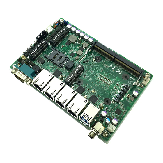
Page 8: Layout Diagram
1* Front panel header 1* Speaker & Power LED header 1* LAN LED activity header 1* RS232 serial port header(COM2, RS232/RS422/485) 1* GPIO_CON header 1* 9-pin USB 2.0 header (Expansible to 2* USB 2.0 ports) ... - Page 9 Motherboard Internal Diagram-Front Side SATAIII Port Front Panel PS/2 Keyboard SATA HDD & Mouse Header Header USB 2.0 HDMI Header Power Connector Header USB 2.0 Header SMBUS Header Serial Port COM1 Port Header Speaker & PWRLED Header GPIO Header Half-size Mini-PCIE Slot (MPE2) LAN1 LANLED...
- Page 10 COPEN Jumper Position: JBAT_ MERTC AT_MODE JPCOM2 Jumper Jumper Name Description JPCOM2 COM2 Header Pin9 Function Select 4-Pin Block AT_MODE ATX Mode / AT Mode Select 3-Pin Block COPEN Case Open Message Display Function 2-Pin Block JBAT_MERTC Pin 1&2: Clear CMOS 6-Pin Block Pin 3&4: Flash Override...
- Page 11 Pin 5&6: POK Override Connectors Name Connector DCIN 12V System DC–in Power Jack Connector USB1 USB 3.0 Port Connector X2 LAN1/2/3/4 RJ-45 LAN Port Connector x 4 COM1 Serial Port Connector ATX2P Internal 12V System DC–in Power Connector CPUFAN CPU Fan Connector SATA1 SATAIII Port Connector STATPWR...
-
Page 12: Chapter 2 Hardware Installation
Chapter 2 Hardware Installation 2-1 Jumper Setting JPCOM2 (4-pin): COM2 Header Pin9 Function Select → JPCOM2 COM2 Header Pin-9 2 4 6 2 4 6 1 3 5 1 3 5 JPCOM2 2-4 Closed: 4-6 Closed: 3-4 Closed: RING( Default); 12V. - Page 13 COPEN (2-pin): Case Open Message Display Function Select COPEN 1-2 Open: 1-2 Closed: Case Open. Normal (Default); Pin (1-2) Close: When Case Open function pin short to GND, the Case Open function was detected. When Used, needs to enter BIOS and enable ‘Case Open Detect’ function.
- Page 14 Pin 3&4 of JBAT_MERTC (6-pin): Flash Override Function Slect → Pin 3&4 of JBAT Flash Override Pin 3 JBAT_MERTC 3-4 Open:Enable Security Measures in the Flash Descriptor(Default); Pin 3 3-4 Closed: Disable Security Measures in the Flash Descriptor(Override). Pin 5&6 of JBAT_MERTC (6-pin): POK Override Function Slect →...
-
Page 15: Connectors And Headers
Connectors and Headers 2-2-1 Connectors (1) Rear I/O Connectors RJ-45 LAN Ports 12V DC-in (LAN1/2/3/4) Power Connector COM1 Serial Port USB 3.0 Ports Icon Name Function For user to connect compatible power 12V DC-in Power adapter to provide power supply for the Connector system. - Page 16 (2) ATX2P (2-pin Block): Internal 12V DC-in Power Connector Warning!! The board has a 12V DC-in power connector (DC_IN) in I/O back panel and an internal ATX2P (ATXPWR) power connector. User can only connect one type of compatible power supply to one of them to power the system. (3) SATA1 (7-pin Block): SATAIII Port connector SATA1 port is a high-speed SATAIII port that supports 6GB/s transfer rate.
- Page 17 (4) SATAPW (4-pin): SATA Power Out Connector SATAPW Warning: Make sure that Pin-1 of compatible SATA Power connector is inserted into corresponding Pin-1 of SATAPW to avoid possible damage to the board and hard disk driver! (5) CPUFAN (4-pin): CPUFAN Connector CPUFAN...
-
Page 18: Headers
2-2-2 Headers (1) JW_FP (9-pin): Front Panel Header JW_FP Pin 1 (2) SPK-LED (8-pin): Speaker & Power LED Header SPK- SPK-LED PWRLED- PWRLED- SPK+ PWRLED+ Pin 1... - Page 19 (3) LAN_LED (8-pin): LAN Activity LED Header LAN_LED Pin 1 (4) COM2 (9-pin): RS232/422/485 Serial Port Header Pin NO. RS232 RS422 RS485 Pin 1 DATA- Pin 2 DATA+ Pin 3 Pin 4 Pin 5 Pin 6 Pin 7 Pin 8 Pin 9 *Notice: COM2 servers as RS232 serial port header in most cases.RS422 &...
- Page 20 to set ‘Transmission Mode Select’ for COM2 as [RS422] or [RS485] for boards that support RS422/485 function before connecting compatible COM cable to COM2 header. (5) GPIO_CON (10-pin): GPIO Header Pin 1 GPIO_CON (6) FP_USB1 (9-pin): USB 2.0 Port Header Pin 1 FP_USB1...
- Page 21 (7) FP_USB2 (4-pin): USB 2.0 Port Header FP_USB2 Pin 1 (8) SMBUS (5-Pin): SMBUS Header SMBUS Pin1...
- Page 22 (9) PS2KBMS (6-pin): PS2 Keyboard & Mouse Port Header PS2KBMS Pin1 (10) HDMI(19-pin): HDMI Port Header HDMI_HPD HDMI HDMI_+5V HDMI_SDA HDMI_SCL HDMI_TXCN HDMI_TXN0 HDMI_TXCP HDMI_TXP0 HDMI_TXN1 HDMI_TXN2 HDMI_TXP1 HDMI_TXP2 Pin 1...
-
Page 23: Chapter 3 Introducing Bios
Chapter 3 Introducing BIOS Notice! The BIOS options in this manual are for reference only. Different configurations may lead to difference in BIOS screen and BIOS screens in manuals are usually the first BIOS version when the board is released and may be different from your purchased motherboard. Users are welcome to download the latest BIOS version form our official website. -
Page 24: Bios Menu Screen
BIOS Menu Screen The following diagram show a general BIOS menu screen: Menu Bar General Help Items Current Setting Value Function Keys Menu Items Function Keys In the above BIOS Setup main menu of, you can see several options. We will explain these options step by step in the following pages of this chapter, but let us first see a short description of the function keys you may use here: ... -
Page 25: Getting Help
Press <+>/<–> keys when you want to modify the BIOS parameters for the active option. [F1]: General help. [F2]: Previous value. [F3]: Optimized defaults. [F4]: Save & Exit. [F7]: To enter pop-up boot menu to select boot device. ... -
Page 26: Main Menu
Main Menu Main menu screen includes some basic system information. Highlight the item and then use the <+> or <-> and numerical keyboard keys to select the value you want in each item. System Date Set the date. Please use [Tab] to switch between data elements. System Time Set the time. -
Page 27: Advanced Menu
3-7 Advanced Menu CPU Configuration Press [Enter] to view current CPU configuration and make settings for the following sub-items: Intel Virtualization Technology The optional settings: [Enabled]; [Disabled]. When set as [Enabled], a VMM can utilize the additional hardware capabilities provided by Vanderpool Technology. - Page 28 Intel(R) SpeedStep(tm) Use this item to enable or disable Intel SpeedStep.When set as [Enabled], it allows more than two frequency ranges to be supported. The optional settings: [Disabled]; [Enabled]. CPU C States Use this item to enable or disable CPU Power Management. When set as [Enabled], it allows CPU to go to C states when it’s not 100% utilized.
- Page 29 TPM Device Selection Use this item to select TPM device. The optional settings are: [dTPM]; [PTT]. Firmware Update Configuration ▶ Press [Enter] to make settings for ‘ME FW Image RE-Flash’. ME FW Image Re-Flash Use this item to enable or disable ME FW Image Re-Flash function. The optional settings: [Disabled];...
- Page 30 Wake-up System with Dynamic Time Use this item to enable or disable system wake on alarm event. System will wake on the current time + Increase minutes. The optional settings: [Disabled]; [Enabled]. When set as [Enabled], system will wake on the current time + increased minute(s).
- Page 31 FIF0]. ► Serial Port 2 Configuration Press [Enter] to make settings for the following sub-items: Serial Port Use this item to enable or disable serial port (COM). Change Settings Use this item to select an optimal setting for super IO device. The optional settings are: [IO=2F8h;...
- Page 32 User can select a value in the range of [10] to [4095] seconds when ‘WatchDog Reset Timer Unit’ set as [Sec]; or in the range of [1] to [4095] minutes when ‘WatchDog Reset Timer Unit ’ set as [Min]. WatchDog Reset Timer Unit The optional settings are: [Sec.];...
- Page 33 Use this item to set CPUFAN idle speed duty. Fan will run at idle speed when below the pre-set duty. Shutdown Temperature Use this item to select system shutdown temperature. The optional settings are: [Disabled]; [70°C/156°F]; [75°C/164°F]; [80°C/172°F]; [85°C/180°F]; [90°C/188°F]. ...
- Page 34 The optional settings are: [None]; [Hardware RTS/CTS]. VT-UTF8 Combo Key Support The optional settings are:[Disabled]; [Enabled]. Recorder Mode The optional settings are: [Disabled]; [Enabled]. Resolution 100x31 The optional settings are:[Disabled]; [Enabled]. Legacy OS Redirection Resolution The optional settings are: [80x24]; [80x25]. Putty Keypad The optional settings are: [VT100];...
- Page 35 Flow Control The optional settings are: [None]; [Hardware RTS/CTS]; [Software Xon/Xoff]. Data Bits The default setting is: [8]. *This item may or may not show up, depending on different configuration. Parity The default setting is: [None]. *This item may or may not show up, depending on different configuration. Stop Bits The default setting is: [1].
- Page 36 Use this item to enable Ipv6 HTTP Boot Support. When set as [Disabled], Ipv6 HTTP boot option will not be created. PXE boot wait time Use this item to set wait time to press [ESC] key to abort the PXE boot. Media Detect Count Use this item to set number of times presence of media will be checked.
- Page 37 The optional settings are: [Enabled]; [Disabled]. USB Mass Storage Driver Support The optional settings are: [Disabled]; [Enabled]. USB hardware delay and time-outs: USB Transfer time-out Use this item to set the time-out value for control, bulk, and interrupt transfers. The optional settings are: [1 sec]; [5 sec]; [10 sec]; [20 sec]. Device reset time-out Use this item to set USB mass storage device start unit command time-out.
-
Page 38: Chipset Menu
3-8 Chipset Menu System Agent (SA) Configuration Press [Enter] to make settings for the following sub-items: VT-d Use this item to enable or disable VT-d capability. The optional settings are: [Enabled]; [Disabled]. * This item might not be available depending on configuration. Graphics Configuration ▶... - Page 39 Aperture Size The optional settings are: [128MB]; [256MB]; [512MB]; [1024MB]. DVMT Pre-Allocated Use this item to select DVMT 5.0 pre-allocated (fixed) graphics memory size used by the internal graphics device. The optional settings are: [32M]; [64M]; [96M]; [128M]; [160M]; [192M]; [224M]; [256M];...
- Page 40 Wake on LAN Use this item to enable or disable integrated LAN to wake the system The optional settings are: [Enabled]; [Disabled]. Onboard Lan2/3/4 Controller Use this item to enable or disable Lan2/3/4 device or controller. The optional settings are: [Enabled]; [Disabled]. MPE1 Slot Use this item to enable or disable device or controller.
-
Page 41: Security Menu
3-9 Security Menu Security menu allow users to change administrator password and user password settings. Administrator Password Press [Enter] to create new administrator password. Press again to confirm the new administrator password. User Password Press [Enter] to create new user password. Press again to confirm the new user password. -
Page 42: Boot Menu
3-10 Boot Menu Boot Configuration Setup Prompt Timeout Use this item to set number of seconds to wait for setup activation key. Bootup Numlock State Use this item to select keyboard numlock state. The optional settings are: [On]; [Off]. Quiet Boot The optional settings are: [Disabled];... -
Page 43: Save & Exit Menu
UEFI Boot The optional settings are: [Disabled]; [Enabled]. [Enabled]: To enable all UEFI boot options. [Disabled]:To disabled all UEFI boot options. 3-11 Save & Exit Menu Save Options Save Changes and Reset This item allows user to reset the system after saving the changes. Discard Changes and Reset This item allows user to reset the system without saving any changes. - Page 44 Save as User Defaults Use this item to save the changes done so far as user defaults. Restore User Defaults Use this item to restore defaults to all the setup options. Boot Override UEFT: Built-in EFI Shell Launch Internal EFI shell application (shell.efi). Lauch EFI Shell from filesystem device Use this item to launch EFI shell application (shell.efi) from one of the available filesystem device.