Table of Contents
Advertisement
Quick Links
Advertisement
Table of Contents

Related Manuals for CyberPower OL6KRT


Summary of Contents for CyberPower OL6KRT
- Page 1 SMART APP ONLINE UPS SYSTEM INSTALLATION AND OPERATION MANUAL OL6KRT | OL8KRT | OL10KRT SAVE THESE INSTRUCTIONS Please read this manual and follow the instructions for installation and operation. ©20 Cyber Power Systems, Inc. All rights reserve. K01-0000754-0...
-
Page 2: Special Symbols
SAFETY INSTRUCTIONS SAVE THESE INSTRUCTIONS This manual contains important instructions that should be followed during installation and maintenance of the UPS and batteries. The Smart App Online 6-10kVA UPS models that are covered in this manual are intended for installation in an environment within 32°F to 104°F (0°C to 40°C), free of conductive contaminants. - Page 3 SAFETY INSTRUCTIONS CONT. PERSONAL SAFETY CAUTION To reduce the risk of fire, connect the UPS to a branch circuit with 40 amperes (6,000 VA)/50 amperes (8,000 VA)/70 amperes (10,000 VA) maximum over-current protection in accordance with the National Electric Code, ANSI/NFPA 70. The AC electrical service where the UPS is connected should be close to the unit and easily accessible.
-
Page 4: Product Safety
SAFETY INSTRUCTIONS CONT. PERSONAL SAFETY CONT. RISK OF ELECTRIC SHOCK CONT. (No User Serviceable Parts): Risk of electric shock, do not remove cover. No user serviceable parts inside. Refer servicing to qualified service personnel. To prevent the risk of fire or electric shock, install in a temperature and humidity controlled indoor area, free of conductive contaminants. - Page 5 SAFETY INSTRUCTIONS CONT. PRODUCT SAFETY CONT. BATTERY Do not dispose of batteries in fire as the battery may explode. Do not open or mutilate the battery, released electrolyte is harmful to the skin and eyes.
-
Page 6: Table Of Contents
TABLE OF CONTENTS SAFETY INSTRUCTIONS..........................II Special Symbols....................................II Personal Safety....................................III Product Safety ....................................IV INTRODUCTION..............................1 Smart App Online UPS Systems..............................1 UPS Extended Battery Modules..............................1 Step-Down Transformer................................1 Unpacking Procedures................................2 Whats In The Box..................................3 OVERVIEW............................4 Power Module....................................4 INSTALLING YOUR UPS SYSTEM........................6 System Block Diagram................................6 Hardware Installation Guide..............................6 HARDWARE INSTALLATION ..........................8 Rackmount Installation ................................8... -
Page 7: Introduction
Equipment Guarantee. UPS EXTENDED BATTERY MODULES Extended Battery Modules (EBMs) from CyberPower increase battery runtimes during power outages. Each rack/tower convertible EBM uses 3U of rack space, depending upon the model, and can be installed in a tower form factor to match the UPS installation. The DC plug-and-play power connectors allow to daisy- chain additional EBMs to a UPS system. -
Page 8: Unpacking Procedures
INTRODUCTION CONT. UNPACKING PROCEDURES Information, advice, help The UPS system is very heavy, please handle with care. Wear safety shoes and use a hydraulic equipment lift if one is available. At least two people are required for all handling operations, including unpacking, lifting, and installation in a rack system. -
Page 9: Whats In The Box
INTRODUCTION CONT. WHATS IN THE BOX ITEM CONTENT ITEM CONTENT Power Module Registration Warranty card PowerPanel Management Software Download Extended Battery Module (EBM) Card Left & Right Rackmount Rails Rackmount Ears Left & Right Hanging Brackets Tie Plate Phone Cable Black M5X7L Flat Head Screws USB Communication Cable Black M5X12L Pan Head Screws... -
Page 10: Overview
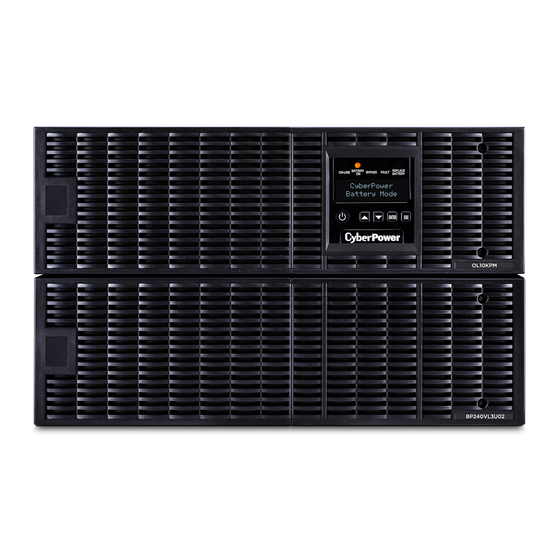
OVERVIEW POWER MODULE FRONT: OL6KPM/OL8KPM/OL10KPM BACK: OL6KPM BACK: OL8KPM/OL10KPM Power Button/Power on Indicator Master ON/OFF switch for the UPS. Indicates that the UPS is on and supplying power. UPS Status/Fault/Replace Battery LED Indicator Indicates the status of the UPS, displaying whether it is operating in On-Line, Battery or Bypass Mode, if it has an internal fault or if the battery needs to be replaced. - Page 11 Expansion Slot A network remote management card is pre-installed in the expansion slot. Extended Battery Module Connector Connection for additional CyberPower Extended Battery Modules (EBM). EPO (Emergency Power O ) Connector Enables an emergency UPS power-o from a remote location.
-
Page 12: Installing Your Ups System
INSTALLING YOUR UPS SYSTEM SYSTEM BLOCK DIAGRAM Bypass Input Inverter Output Input Output Filter AC/DC DC/AC Filter LCD Module Charger Control Battery AC/DC & USB & DB9 Monitoring SNMP Slot Line Mode Battery Mode Bypass Mode HARDWARE INSTALLATION GUIDE Battery charge loss may occur during shipping and storage. Before using the UPS, it’s strongly recommended to charge batteries for four hours to ensure the batteries’... - Page 13 When the high temperature sensor activates protection, the UPS generates an alarm and shuts down to avoid unexpected equipment damage. When the over temperature occurs, please check the Troubleshooting section. If the condition persists, please contact CyberPower for technical support.
-
Page 14: Hardware Installation
HARDWARE INSTALLATION CyberPower UPS systems can be installed in a rackmount or vertical/tower orientation. This versatility is especially important to growing organizations with changing needs that value having the option to position a UPS on the floor or in a rackmount system. Note that the included rack mounting hardware is only compatible with square hole racks. - Page 15 HARDWARE INSTALLATION CONT. RACKMOUNT INSTALLATION: RACKMOUNT EARS INSTALLATION CONT. Rackmount ear Rackmount rail Step 5: Place and secure the UPS on the rails Slide the hanging brackets on the UPS on to the rails mounted in the rack with the front of the unit facing toward you.
-
Page 16: Vertical/Tower Installation
HARDWARE INSTALLATION CONT. VERTICAL/TOWER INSTALLATION Step 1: Adhere rubber pads Adhere the protective rubber pads to the left hand side of the UPS power module and extended battery module. Step 2: Attach the base stands and attach the dust covers Stand the UPS power module and extended battery module on its side. -
Page 17: Electrical Installation
Local safety rules may require a separate, external EPO to turn o output circuit breakers. Refer to local wiring rules, the EPO should use approved components. OL6KRT Electrical Connection Connect the NEMA L6-30P input power cord on the UPS to a properly wired NEMA L6-30R outlet. See the... -
Page 18: Backfeed Protection Operation
Warning! A CyberPower Step-Down Transformer is required for supplying 120V output to connected equipment. To prevent damage to connected equipment, do not attempt to separate the output voltage, from the hardwire block or outlets, into two 120V outputs on this UPS. If you attempt to supply two separate 120V outputs to your equipment, that equipment can be damaged when the UPS switches to battery mode. -
Page 19: Without Backfeed Protection Configuration
ELECTRICAL INSTALLATION CONT. WITHOUT BACKFEED PROTECTION CONFIGURATION Hardwire the input terminals as shown in the following diagram. 2. Do not remove the interconnection wires (Jumper1 / Jumper2) on “Backfeed Protection Connector”. Mains L1 L2 PE IP-L1 IP-L2 PSDR Backfeed Jumper1 AC-L1 Jumper2 AC-L2... -
Page 20: With Backfeed Protection Configuration
EXTENDED BATTERY MODULE INSTALLATION REAR PANEL DESCRIPTION BP240VL3U01 / BP240VL3U02 On-board Replaceable Fuse Cover Replaceable fuse is accessible from the rear panel. Service to be performed by qualified personnel only. AC Circuit Breaker Provides overload and fault protection. AC Output Outlet (IEC320 C13) Use this outlet to connect to the AC Input Inlet of a downstream Battery module. - Page 21 EXTENDED BATTERY MODULE INSTALLATION CONT. CONNECTION WITH POWER MODULE CONT. Step 1: Turn o the DC breaker on the EBM. Step 2: Loosen the two screws to remove the battery cable retention bracket of the power module. Step 3: Use the output cable of the EBM to connect the EBM to the Power module. Step 4: Rotate the battery cable retention bracket and tighten the two screws to fix battery cable.
- Page 22 EXTENDED BATTERY MODULE INSTALLATION CONT. CONNECTION WITH POWER MODULE CONT. Step 1: Connect the 1st EBM to the Power module following the instructions above. Step 2: Turn o the DC breaker of the 2nd EBM. Step 3: Loosen the two screws to remove the battery cable retention bracket of the 1st EBM. Step 4: Use the output cable of the 2nd EBM to connect the 2nd EBM to the 1st EBM.
-
Page 23: Optional Lcd Control Panel Installation
OPTIONAL LCD CONTROL PANEL INSTALLATION Caution: Important Instructions Optional LCD control panel installation must be done by qualified personnel. To avoid electric shock, turn o and unplug the unit before proceeding with REMOTE CONTROL or WALL- MOUNTING INSTRUCTIONS. REMOTE CONTROL Step 1: Remove the LCD Control Panel Unscrew the right front panel of the power module. -
Page 24: Ups System Startup
5. Set the upstream circuit breaker (user supplied) to the “ON” position. The UPS LCD will turn on and display “CyberPower”; fans will turn on. 6. Press the ON/OFF button on the UPS front panel for at least 3 seconds to start the UPS. -
Page 25: Using The Ups System
USING THE UPS SYSTEM LCD CONTROL PANEL LED INDICATORS - UPS STATUS ITEM LED INDICATORS COLOR UPS STATUS DESCRIPTION ON/OFF White UPS power is on. ON-LINE Green UPS is operating in Line Mode. BATTERY ON Yellow UPS is operating in Battery Mode. UPS is operating in Bypass Mode, Manual BYPASS Yellow... -
Page 26: Lcd Menu Tree
USING THE UPS SYSTEM CONT. LCD CONTROL PANEL CONT. LCD SCREEN - UPS MODES OF OPERATION LCD SCREEN UPS MODES DESCRIPTION UPS is operating in Line Mode. Line Mode The UPS is operating normally and protecting the equipment. UPS is operating in Battery Mode. Battery Mode A utility power failure has occurred. - Page 27 USING THE UPS SYSTEM CONT. LCD Control Panel Main Menu Press “ENTER” button to enter the “Main Menu”. MAIN MENU DESCRIPTION Information Displays UPS information. Configure Displays UPS settings that can be configured by the user. Displays the 5 most recent events, by event count, time (day/hour/minute), Event Log and event description.
- Page 28 USING THE UPS SYSTEM CONT. LCD Information Readout Cont. INFORMATION DATA DESCRIPTION MENU ITEMS DISPLAYED Date & Time - - - - / - - / - - - -:- - Displays the present Date & Time Next BATT XXX / XXXX Displays the next Battery Change Date &...
- Page 29 USING THE UPS SYSTEM CONT. LCD Event Log Cont. EVENT CONTENT DESCRIPTION Service Battery The Battery Replacement Date has reached the maintenance period. Battery Failure The UPS has detected battery failure. The UPS has detected input power is out of range when the UPS is running auto- Line Abnormal restart process.
- Page 30 USING THE UPS SYSTEM CONT. LCD Configuration Settings Cont. 8. Press the “ENTER” button to select the parameter you want to change. 9. You may be prompted to save the selection, if so press the “ENTER” button to save the setting. Some options are saved and started automatically.
- Page 31 USING THE UPS SYSTEM CONT. LCD Configuration Settings Cont. CONFIGURE AVAILABLE SETTINGS DEFAULT SETTING SUBMENU [Disable] [Enable] Disable [V Range= +/-15%] [V Range= +/-10%] (for [Enable]) When ECO mode is enabled the UPS will check the following bypass quality specifications ECO Mode V Range= +/-10% Bypass voltage is inside the [V Range= +/-10%]...
- Page 32 USING THE UPS SYSTEM CONT. LCD Configuration Settings Cont. CONFIGURE AVAILABLE SETTINGS DEFAULT SETTING SUBMENU [English] [Español-Spanish] [Français-French] [Deutsch-German] Language English User can select the desired LCD control panel language. [Disable] [Enable] When the UPS input power source is a generator set Generator Mode Disable the UPS will operate normally without transferring to...
- Page 33 USING THE UPS SYSTEM CONT. LCD Configuration Settings Cont. CONFIGURE AVAILABLE SETTINGS DEFAULT SETTING SUBMENU [Disable] [EPO] [ROO][Manual Bypass] Set [EPO] (Emergency Power O ) to shut down the UPS remotely when the contact is open. Set [ROO] (Remote On/O ) to turn the UPS on remotely when the contact is closed and turn the UPS o remotely Signal Inputs Disable...
- Page 34 USING THE UPS SYSTEM CONT. Manual Battery Test Select “Activate” in the “Battery Test” option of the LCD control panel and the unit will perform a manual battery test. Graphic Load/Battery Capacity Display Press the “ESC” button to return to UPS Status. 2.
-
Page 35: Maintenance
MAINTENANCE Storage To store your UPS for an extended period of time, cover and store it with the battery fully charged. Recharge the battery every three months to ensure battery life. Battery Replacement Please read and follow the Safety Instructions before servicing the battery. Battery replacement should be performed by trained personnel who are familiar with the procedures and safety precautions. -
Page 36: Battery Replacement
MAINTENANCE CONT. BATTERY REPLACEMENT Step 1: Remove the front panels. Step 2: Remove the retaining screws from the battery retention cover and then remove the cover itself. Step 3: Pull the battery trays out slowly and then put the new battery trays into the compartment. Step 4: Insert the battery connectors and tighten the screws of battery retention cover. -
Page 37: Technical Specifications
Recharge Time 0-90% 4 hours 5 hours (Typical) *OL6KRT output power will be derated base on input voltage as following 6,000 (6 kVA) at 220, 230, 240 V input 5,400 (5.4 kW) at 220, 230, 240 V input Watts 5,400 (5.4 kVA) at 208 V input 4,860 (4.86 kW) at 208 V input... - Page 38 TECHNICAL SPECIFICATIONS CONT. MODELS OL6KRT OL8KRT OL10KRT BATTERY CONT. Sealed, Maintenance Free Hot-Swappable STATUS INDICATORS Multi-Function LCD Readout that Supports: LCD Screen Multi-Language Interface, (24) Types of Read Out, (30) Types of Function Setting, (5) Event Logs Power On (White), Line Mode (Green), Battery Mode (Yellow),...
- Page 39 TECHNICAL SPECIFICATIONS CONT. MODELS BP240VL3U01 BP240VL3U02 CONFIGURATION AC Input Voltage 180~280 V DC Output Voltage 240 Vdc DC Output Current 30 A 50 A PHYSICAL Dimensions L x W x H = 26 x 17.05 x 5.2 in (660 x 433 x 132 mm) Net Weight 167.2 lb (76 Kg) 171.6 lb (78 Kg)
-
Page 40: Troubleshooting
TROUBLESHOOTING PROBLEM POSSIBLE CAUSE SOLUTION WARNING Your equipment requires more power than the UPS can provide. If the UPS Shut o non-essential equipment. If O/P Overload is in Line Mode then it will transfer to this solves the overload problem, the Bypass Mode;... -
Page 41: Product Registration
PRODUCT REGISTRATION CyberPower requests that you complete and return the Warranty Registration Card enclosed with the Product or register the Product at its website (www.cyberpowersystems.com/registration) to establish that you are the Initial Customer of the Product, and therefore entitled coverage under the Limited Warranty and the Connected Equipment Guarantee. -
Page 42: Limited Warranty And Connected Equipment Guarantee
LIMITED WARRANTY AND CONNECTED EQUIPMENT GUARANTEE Read the following terms and conditions carefully before using the CyberPower OL6KRT/OL8KRT/ OL10KRT. By using the Product you consent to be bound by and become a party to the terms and conditions of this Limited Warranty and Connected Equipment Guarantee (together referred to as this “Warranty”). - Page 43 If the Product is defective in material or workmanship, CyberPower will repair or replace it at CyberPower's expense, or, if CyberPower is unable to or decides not to repair or replace the Product (if defective) within a reasonable time, CyberPower will refund to you the full purchase price you paid for the Product (purchase receipt showing price paid is required).
- Page 44 1ms has occurred, the occurrence will be deemed outside the rated capabilities of the Product and the Limited Warranty is void. CyberPower Does Not Cover or Undertake Any Liability in Any Event for Any of the Following: Loss of or damage to data, records, or software or the restoration of data or records, or the reinstallation of software.
- Page 45 (collectively, "High Risk Activities"). CyberPower expressly disclaims any express or implied warranty of fitness for High Risk Activities or with aquariums. CyberPower does not authorize use of any Product in any High Risk Activities or with Aquariums. ANY SUCH USE IS IMPROPER AND IS A MISUSE OF THE PRODUCT.
-
Page 46: Conformance Approval
Cet appareil numerique de la class A respecte toutes les exigencies du Reglement sur le materiel brouilleur du Canada. This document is believed to be accurate, but CyberPower reserves the right to change or correct the contents and does not assume any responsibility for omissions or errors. - Page 47 Cyber Power Systems, Inc. | For USA and Canada | 4241 12th Ave East, Suite 400, Shakopee, MN 55379 | Toll-free: 877.297.6937 For all other regions | Please visit our website for local contact information. Copyright © 20 Cyber Power Systems, Inc. All rights reserve.