
Related Manuals for Honeywell SmartLine STIW400


Summary of Contents for Honeywell SmartLine STIW400
- Page 1 SmartLine Wireless Temperature and Universal I/O Transmitters User’s manual 34-SW-25-04 Revision 1 December 2019 Honeywell Process Solutions...
- Page 2 In no event is Honeywell liable to anyone for any indirect, special or consequential damages. The information and specifications in this document are subject to change without notice.
- Page 3 Temperature Transmitters. Mounting, installation and wiring are covered in other documents. Honeywell does not recommend using devices for critical control where there is a single point of failure or where single points of failure result in unsafe conditions. OneWireless is targeted at open loop control, supervisory control, and controls that do not have environmental or safety consequences.
- Page 4 Support and Contact Information For Europe, Asia Pacific, North and South America contact details, refer to the back page of this manual or the appropriate Honeywell Support web site: Honeywell Corporate www.honeywell.com Honeywell Process Solutions https://www.honeywellprocess.com/* Training Classes https://www.honeywellprocess.com/en-US/training Telephone and Email Contacts...
- Page 5 Symbol Definitions The following table lists those symbols used in this document to denote certain conditions. Symbol Definition ATTENTION: Identifies information that requires special consideration. TIP: Identifies advice or hints for the user, often in terms of performing a task. Indicates a situation which, if not avoided, may result in equipment or work (data) on CAUTION the system being damaged or lost, or may result in the inability to properly operate...
- Page 6 Symbol Description ® The Factory Mutual Approval mark means the equipment has been rigorously tested and certified to FM standards for safety and/or performance. The Canadian Standards mark means the equipment has been tested and meets applicable standards for safety and/or performance. The Ex mark means the equipment complies with the requirements of the European standards that are harmonized with the 94/9/EC Directive (ATEX Directive, named after the French "ATmosphere EXplosible").
-
Page 7: Table Of Contents
Contents INTRODUCTION ....................1 Purpose ............................1 Scope ............................. 1 OneWireless network overview ....................1 Security Considerations ......................1 About the transmitter ........................3 Physical Characteristics ......................5 PREPARATION AND QUICK START ..............7 Introduction ..........................7 Set up the Network ........................7 Transmitter Quick Start ....................... - Page 8 Contents Symbol Definitions I/O Types ............................. 30 STIW400 Terminal Connections ....................31 STUW750 Terminal Connections ....................32 STUW751 Terminal Connections ....................33 POWER AND START UP ................... 34 Battery Power Option......................... 34 Install/Replace batteries ............................34 Battery Pack installation and replacement procedure ..................36 Battery Pack Test Terminals ..........................
- Page 9 Contents Symbol Definitions Introduction ..........................59 Transmitter Firmware upgrade ....................59 Preventive maintenance ......................59 Replacing Electronics Module ....................60 Tools required ..............................60 Procedure ................................60 Replacing batteries ........................61 When to replace ..............................61 Replacing 24V external power module ..................61 When to replace ..............................
- Page 10 Contents Tables Tables Table 3-1: Weights ........................10 Table 3-2: Drawing numbers for temperature/UIO transmitters ..........13 Table 3-3: Conduit entry plugs and cable glands for your transmitter........14 Table 6-1: Blocks........................42 Table 7-1: Transmitter connection status .................. 43 Table 7-2: Transmitter PV display ....................
- Page 11 Contents Figures Figures Figure 1-1 - SmartLine Wireless Transmitter Functional Diagram ..........4 Figure 1-2 – SmartLine Wireless Transmitter Major Assembly ........... 5 Figure 1-3– SmartLine Wireless Transmitter Electronics Housing Components ......6 Figure 3-1: Temperature/UIO transmitter dimensions’ unit mm/inch ......... 11 Figure 3-2: Temperature/UIO antenna dimensions unit mm/inch ..........
- Page 12 This page has been intentionally left blank SmartLine Wireless Temperature and Universal I/O User's Manual Revision 1...
-
Page 13: Introduction
This manual describes the Honeywell SmartLine Wireless Transmitter function, operation and maintenance. Scope The manual includes: Details of topics that relate uniquely to the Honeywell SmartLine Wireless Transmitter OneWireless network overview OneWireless is an all digital, two-way communication mesh network that interconnects industrial field sensors to a central system. - Page 14 1. Introduction 1.4. Security Considerations Firmware image for this transmitter is protected by Honeywell PKI signing process. This ensures that only firmware that has a valid signature can be used to update the transmitter. If the new firmware image fails signature validation, it will be discarded and the transmitter will continue operate with previous version of the firmware.
-
Page 15: About The Transmitter
1. Introduction 1.5. About the transmitter About the transmitter The SmartLine Wireless Transmitter is furnished with an ISA100.11a-compliant wireless interface to operate in a compatible distributed ISA100.11a wireless system. The transmitter will interoperate with any ISA100.11a wireless network. The transmitter includes ISA100.11a-compliant electronics for operating in a 2.4 GHz wireless network. -
Page 16: Figure 1-1 - Smartline Wireless Transmitter Functional Diagram
1. Introduction 1.5. About the transmitter STUW750 Channel 1 Channel 2 Channel 3 T/C or mV or DI or 2-wire T/C or mV or DI or 2-wire T/C or mV or DI or 2-wire resistance or current resistance or current resistance or current (0/4-20mA) (0/4-20mA) -
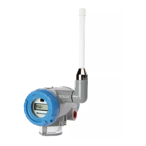
Page 17: Physical Characteristics
1. Introduction 1.6. Physical Characteristics Physical Characteristics As shown in Figure 1-2, the SmartLine Wireless transmitter is packaged in one major assembly: the Electronics Housing with the Housing Adaptor. The elements in the Electronic Housing respond to IR commands and execute the software and protocol for the different temperature measurement types. Figure 1-3 shows the assemblies in the Electronics Housing. -
Page 18: Figure 1-3- Smartline Wireless Transmitter Electronics Housing Components
1. Introduction 1.6. Physical Characteristics Figure 1-3– SmartLine Wireless Transmitter Electronics Housing Components SmartLine Wireless Temperature and Universal I/O User's Manual Revision 1... -
Page 19: Preparation And Quick Start
2. Preparation and Quick Start 2.1. Introduction 2. Preparation and Quick Start Introduction This section is useful if you are unfamiliar with the SmartLine Wireless transmitter, want a quick start list, or if you want to configure and test your transmitter in an office environment before installing it in its final location. - Page 20 2. Preparation and Quick Start 2.3. Transmitter Quick Start 5. VERIFY that the transmitter appears in the wireless network. This step may take several minutes, depending on your network. a. Drag the transmitter icon from the selection panel to the map (optional) b.
-
Page 21: Installation
Evaluate the site selected for the SmartLine Wireless Transmitter installation with respect to the process system design specifications and Honeywell’s published performance characteristics for your particular model. Some parameters that you may want to include in your site evaluation are: •... -
Page 22: Transmitter Weights And Dimensions
3. Installation 3.3. Transmitter Weights and Dimensions Transmitter Weights and Dimensions Weights Table 3-1: Weights Transmitter Model Weight STIW400 6 lbs (2.7 kg) STUW75X Note: Add 8.0 pounds (3.6 kg) to any model equipped with the stainless-steel housing option (Model Selection Guide Table IV selections M or N) SmartLine Wireless Temperature and Universal I/O User's Manual Revision 1... -
Page 23: Figure 3-1: Temperature/Uio Transmitter Dimensions' Unit Mm/Inch
3. Installation 3.3. Transmitter Weights and Dimensions Dimensions Figure 3-1: Temperature/UIO transmitter dimensions’ unit mm/inch Revision 1 SmartLine Wireless Temperature and Universal I/O User's Manual... -
Page 24: Figure 3-2: Temperature/Uio Antenna Dimensions Unit Mm/Inch
3. Installation 3.3. Transmitter Weights and Dimensions Figure 3-2: Temperature/UIO antenna dimensions unit mm/inch SmartLine Wireless Temperature and Universal I/O User's Manual Revision 1... -
Page 25: Installation Drawing Number Tables
3. Installation 3.4. Installation drawing number tables Installation drawing number tables If an installation drawing from the table below is required, please contact your local Honeywell representative. Refer to Honeywell drawing numbers in Table 3-2 for detailed dimensions. Abbreviated overall dimensions are also shown on the Specification Sheets for the transmitter models, see References. -
Page 26: Conduit / Cable Entries
3. Installation 3.5. Conduit / Cable Entries Conduit / Cable Entries THIS PRODUCT IS SUPPLIED WITH PLASTIC DUST PLUGS IN THE CONDUIT/CABLE GLAND ENTRIES. IT IS THE USERS NOTICE RESPONSIBILITY TO PROVIDE CABLE GLANDS, ADAPTORS AND/OR BLANKING PLUGS SUITABLE FOR THE ENVIRONMENT IN WHICH THIS PRODUCT IS INSTALLED. -
Page 27: Mounting Summary
3.6. Mounting Summary Mounting Summary Transmitter models can be attached to a two-inch (50 millimeter) vertical or horizontal pipe using Honeywell’s optional angle or flat mounting bracket; alternately you can use your own bracket. Figure 3-3 shows typical bracket-mounted transmitter installations. -
Page 28: Figure 3-4: Typical Angle Bracket Mounted
3. Installation 3.6. Mounting Summary Figure 3-4: Typical Angle Bracket Mounted SmartLine Wireless Temperature and Universal I/O User's Manual Revision 1... -
Page 29: Figure 3-5: Pipe Mounting Bracket Secured To A Horizontal Or Vertical Pipe
3. Installation 3.6. Mounting Summary Bracket Mounting Procedure 1. Align the two mounting holes in the transmitter with the two slots in the mounting bracket and assemble the (2) M8 hex cap screws, (2) lockwashers and (2) flat washers provided. Rotate transmitter assembly to the desired position and torque the M8 hex cap screws to 27,0 Nm/20,0 Lb-ft maximum. -
Page 30: Rotate Transmitter Housing
3. Installation 3.7. Rotate transmitter housing Rotate transmitter housing You can rotate the transmitter for better viewing, access, or antenna position. Loosen set screw (see A in Figure 3-6) on outside neck of transmitter one full turn. Rotate transmitter housing up to 180 degrees in either direction to desired position. -
Page 31: Rotate Display
Display adjustment Step Action Honeywell recommends that the transmitter be removed from service and moved to a clean area before servicing. Loosen the M3 locking set screw on the display end-cap. See item 1 in Figure 3-7 Unscrew and remove the end cap. -
Page 32: Figure 3-7: Display Rotation
3. Installation 3.8. Rotate display Figure 3-7: Display rotation SmartLine Wireless Temperature and Universal I/O User's Manual Revision 1... -
Page 33: Antenna Adjustment And Mounting
3. Installation 3.9. Antenna adjustment and mounting Antenna adjustment and mounting Requirements Radio installation requirements ATTENTION Professional Installation is required to insure conformity with Federal Communications Commission (FCC) in the USA, Industry Canada (IC) in Canada and the Radio and Telecommunications Terminal Equipment Directive, 1999/5/EC (R&TTE), in the European Union (EU). -
Page 34: Figure 3-8: Elbow Antenna Adjustment
3. Installation 3.9. Antenna adjustment and mounting Figure 3-8: Elbow antenna adjustment If your model has the integral elbow antenna you can adjust it to improve reception. Typically, pointed straight up gives best performance but your installation may vary. Loosen the 1.5mm set screw located near the antenna base. -
Page 35: 3.10 Remote Antenna
3. Installation 3.10. Remote antenna 3.10 Remote antenna Outdoor installation warnings WARNING LIVES MAY BE AT RISK! Carefully observe these instructions and any special instructions that are included with the equipment you are installing. WARNING Contacting power lines can be lethal. Look over the site before beginning any installation, and anticipate possible hazards, especially these: Make sure no power lines are anywhere where possible contact can be made. -
Page 36: Choosing A Mounting Location
3. Installation 3.10. Remote antenna WARNING If a person comes in contact with electrical power, and cannot move: DON’T TOUCH THAT PERSON, OR YOU MAY BE ELECTROCUTED. Use a non-conductive dry board, stick or rope to push or drag them so they no longer are in contact with electrical power. -
Page 37: Mounting The Antenna
Antennas are provided with a mast mounting kit consisting of a mounting bracket and two U-bolt clamps. This kit allows you to mount the antenna to masts with outside diameters (O.D.) from 1.25 inches (3.2 centimeters) to 2 inches (5.1 centimeters). Honeywell recommends that a 1.5 inch (3.8 centimeter) or larger tubing mast be used. -
Page 38: Directional Mounting Procedure
3. Installation 3.10. Remote antenna Step Action When attaching the coax cable to the SmartLine Wireless transmitter, it is recommended that a drip loop with a radius of at least 12 inches (30 cm) be formed close to the SmartLine transmitter. -
Page 39: Omnidirectional Mounting Procedure
3. Installation 3.10. Remote antenna Figure 3-9: Directional antenna mounting Omnidirectional mounting procedure Step Action Secure mast mounting bracket to mast as shown using 2 U-bolts and supplied hardware. Remove antenna mounting bolt and washer from antenna base. Insert antenna into mounting bracket and secure with washer and antenna mounting bolt. Do not overtighten. -
Page 40: Grounding The Antenna
The lightning arrestor sold by Honeywell features a bulkhead N-Female connector with a rubber “O”-ring seal which can be used for mounting through an enclosure wall. The lightning arrestor can also be mounted using the included stainless steel mounting bracket. - Page 41 3. Installation 3.10. Remote antenna Step Action CAUTION There may be wires in the wall. Before drilling check that the area is clear of any obstructions or other hazards. Pull the cable through the hole and form a drip loop on the outside close to where the cable enters the building.
-
Page 42: Sensor And Electrical Connections
4. Sensor and Electrical Connections 4.1. Introduction 4. Sensor and Electrical Connections Introduction This section explains the sensor connections I/O Types The transmitter accepts the following types of I/O and ranges Transmitter I/O Type Configurable Range / parameters STIW400, STUW750, Thermocouple types B, E, J, STUW751 K, N, R, S, T... -
Page 43: Stiw400 Terminal Connections
4. Sensor and Electrical Connections 4.3. STIW400 Terminal Connections STIW400 Terminal Connections T/C or mV or DI or 2 Wire Resistance 3 Wire RTD or Resistance T/C or mV or DI or 2 Wire Resistance 3 Wire RTD or Resistance Figure 4-1: STIW400 Terminal Connections NOTES: 1. -
Page 44: Stuw750 Terminal Connections
4. Sensor and Electrical Connections 4.1. STUW750 Terminal Connections STUW750 Terminal Connections HLAI (0/4-20mA) or T/C or mV or DI or 2 Wire Resistance Figure 4-2: STUW750 Terminal Connections NOTES: 1. The terminals accept 14-26AWG wire, and the screws shall be torqued to 0.4-0.5Nm (3.5 – 4.4 in-lb) 2. -
Page 45: Stuw751 Terminal Connections
4.2. STUW751 Terminal Connections STUW751 Terminal Connections HLAI (0/4-20mA) or T/C or mV or DI or 2 Wire Resistance AND Digital Output PV3 Digital Output Figure 4-3: STUW751 Terminal Connections NOTES: 1. The terminals accept 14-26AWG wire, and the screws shall be torqued to 0.4-0.5Nm (3.5 – 4.4 in-lb) 2. -
Page 46: Power And Start Up
Eagle Picher PT-2300H • Tadiran TL-5930/s • Tadiran GmbH, SL-2780 (Not approved by FM or CSA) • Honeywell p/n 50026010-501 (Two 3.6V lithium thionyl chloride batteries) • Honeywell p/n 50026010-502 (Four 3.6V lithium thionyl chloride batteries) • Honeywell p/n 50026010-503 (Ten 3.6V lithium thionyl chloride... -
Page 47: Figure 5-1: Is Battery Pack Installation
5. Power and Start up 5.1. Battery Power Option Figure 5-1: IS Battery Pack Installation Battery Pack Repalcement Battery Pack (without batteries) Honeywell part number: 50047517-501 Figure 5-2: IS Battery Pack Revision 1 SmartLine Wireless Temperature and Universal I/O User's Manual... -
Page 48: Battery Pack Installation And Replacement Procedure
Reconnect the Battery Pack power connector to the transmitter Ensure all wires are free of the threads to allow the cap to be re-installed Honeywell recommends lubricating the end cap threads with a silicone grease such as Dow Corning #55 or equivalent before replacing the end cap... -
Page 49: Power Supply Option
5. Power and Start up 5.2. 24V Power Supply Option 24V Power Supply Option ELECTRICAL CONNECTION SPECIFICATIONS The 24V power supply requires 16 Vdc to 28 Vdc, 100 mA max supply connection to the 24V wiring connector terminals. For hazardous location installation, and intrinsic safety entity parameters, refer to the control drawing. -
Page 50: 24V Power Supply
5. Power and Start up 5.2. 24V Power Supply Option 24V Power Supply Replacement 24V Power Supply Honeywell part number: 50136118-501 Figure 5-4: 24V Power Supply Module SmartLine Wireless Temperature and Universal I/O User's Manual Revision 1... -
Page 51: 24V Power Supply Connection/Replacement Procedure
Ensure all wires are free of the threads to allow the cap to be re-installed. Honeywell recommends lubricating the end cap threads with a silicone grease such as Dow Corning #55 or equivalent before replacing the end cap Screw the cap back on and tighten the M3 locking screw... -
Page 52: Grounding
5. Power and Start up 5.3. Grounding Grounding If the transmitter is not grounded solidly through the meterbody mounting, ground the transmitter by connecting a wire from the Earth Ground Clamp on the side of the transmitter to Earth Ground as short as possible. Use a size 8AWG or (8.37 mm ) bare or green covered wire for this connection. -
Page 53: Display Sequence
5. Power and Start up 5.4. Display sequence Display sequence After power up, the transmitter will display its startup sequence which includes the firmware revision. It will then perform a sensor check and proceed to connecting to the wireless network. A series of messages will be displayed depending on the network connection status. -
Page 54: Function Blocks
6. Function blocks 6.1. Introduction 6. Function blocks Introduction This section explains the construction and contents of the SmartLine Wireless Transmitter Function Blocks. Block description Block types Blocks are the key elements that make up the transmitter’s configuration. The blocks contain data (block objects and parameters) which define the application, such as the inputs and outputs, signal processing and connections to other applications. -
Page 55: Operation
7. Operation 7.1. Transmitter connection status 7. Operation Transmitter connection status Table 7-1: Transmitter connection status Displayed Definition What to do status NO-KEY Transmitter needs a key from the Transmit a key to the transmitter. Provisioning Device and is not transmitting. See page 52. - Page 56 UNJOINED in this table. -No MAC- The Radio Has not been assigned a MAC Contact Honeywell Support. A new radio is address at the factory. required. JOINED Transmitter has validated the key and has No action required.
-
Page 57: Transmitter Pv Display
7. Operation 7.2. Transmitter PV display Transmitter PV display In PV display, the following information is displayed in sequence. Table 7-2: Transmitter PV display Item displayed Example Details PV value Latest PV value. PV engineering units OHMS Table 7-5. PV status Table 7-5. -
Page 58: Pv Status
Sensor Failure has occurred or the transmitter was unable to communicate ‘F’ with the sensor. • Check the connection between the Sensor and the Main Board of the transmitter. • Contact Honeywell Support if the problem persists. SmartLine Wireless Temperature and Universal I/O User's Manual Revision 1... -
Page 59: Table 7-4: Device Status
7. Operation 7.2. Transmitter PV display Table 7-4: Device status Transmitter display OneWireless User Definition What to do Interface display All channels are out of Restore mode to Auto in service. OneWireless User Interface. SNSR ERR Sensor Error Sensor can not access Check connection between meter body A/D electronics module and meter... - Page 60 7. Operation 7.2. Transmitter PV display Transmitter display OneWireless User Definition What to do Interface display ‘U’ Status Excess Span The calibrated upper Clear Calibration Calibration and lower trim has produced a span that is greater than 5% of the Set Factory Calibration characterized span of the transmitter.
-
Page 61: Table 7-5: Smartline Temp-Uio Units
7. Operation 7.2. Transmitter PV display Table 7-5: SmartLine TEMP-UIO units Temperature Description degC Celsius degF Fahrenheit RTD, 2W and 3W resistance Percent Voltage Millivolts HLAI Milliamps Percent Digital Input and Digital Output ON/OFF ON or OFF state Table 7-6: Radio menu RADIO Radio menu PRI RSSI... -
Page 62: Transmitter Channel Configuration
7. Operation 7.3. Transmitter Channel Configuration Transmitter Channel Configuration Channel Status Using the WDM interface, each transmitter channel can be configured as per available options. More details about the WDM interface can be found in References. After provisioning, or after transmitter is reset to default settings, the channels are not enabled (Unassigned) and the LCD indicates: “NoChEn”. -
Page 63: Cold Junction
7. Operation 7.3. Transmitter Channel Configuration Cold Junction The Cold Junction values is available for Thermocouple channels only and it is shown in the Channel ->Sensor menu. The value is also available for monitoring over the OPC interface. CJ value is updated at a lower rate than the normal PV publish rate. Digital Inputs The discrete input channels support voltage-free floating contacts. -
Page 64: Provisioning Device Menus
7. Operation 7.4. Provisioning Device menus Provisioning Device menus Overview Hold the Provisioning Device no more than 6” (15 cm) from the transmitter and aim the infrared beam at the transmitter display while tapping on the screen command or button. Main menu The main menu is shown below. -
Page 65: Figure 7-2: Security And Node Deployment
7. Operation 7.4. Provisioning Device menus Figure 7-2: Security and Node Deployment To connect your transmitter to the OneWireless network perform the following steps. Step Action If the Provisioning Device contains no keys, obtain new security keys from the WDM Provisioning tab When the Provisioning Device has valid unexpired keys, aim it at the transmitter and transmit a key to the transmitter. -
Page 66: De-Provisioning
7. Operation 7.4. Provisioning Device menus De-provisioning To de-provision the transmitter from the network and reset all settings to their default factory values, select Reset Device to Defaults. To simply remove the device from the network select the transmitter in the WDM and click Delete. This will remove the device from the network and you will have to manually accept it back onto the network via the WDM interface if you want it to re- join the same network. -
Page 67: Table 7-7: Read Device Information
7. Operation 7.4. Provisioning Device menus Table 7-7: Read Device Information Item Description Tag Name: The name given to this transmitter Vendor: Manufacturer of device Model: Description of device Revision: Software revision of sensor firmware Radio Version: Software revision of radio firmware Serial Number: Transmitter serial number. -
Page 68: Advanced Options
7. Operation 7.4. Provisioning Device menus Advanced Options Advanced options are non-typical configuration commands. Figure 7-4: Advanced Options SmartLine Wireless Temperature and Universal I/O User's Manual Revision 1... -
Page 69: Calibrating The Transmitter
7. Operation 7.5. Calibrating the transmitter Table 7-8: Advanced Options Item Description Read Power Level Reads the transmission power level of the transmitter radio. Read Tag Name Reads the transmitter’s tag name Write Tag Name Write the transmitter’s tag name with the entered text, maximum 16 characters Calibrating the transmitter Overview... -
Page 70: Two Point Calibration
7. Operation 7.5. Calibrating the transmitter Two Point Calibration For Two Point Calibration, the user applies two known inputs to the transmitter channel, one High and one Low. At each point the User will enter the known input value into either CAL POINT HIGH or CAL POINT LOW in the Calibration interface in the WDM, and then set Cal Cmd to the appropriate command, either CAL UPPER or CAL LOWER. -
Page 71: Maintenance/Repair
8. Maintenance/Repair 8.1. Introduction 8. Maintenance/Repair Introduction This section provides information about firmware upgrade, preventive maintenance routines and replacing damaged parts. The topics covered in this section are: • Replacement of damaged parts such as the transmitter display/sensor and batteries. Transmitter Firmware upgrade The SmartLine Wireless Temperature/UIO Transmitter allows firmware to be updated Over The Air (OTA). -
Page 72: Replacing Electronics Module
Table 8-1: Electronics module replacement Step Action Honeywell recommends that the transmitter be removed from service and moved to a clean area before servicing. Loosen the M3 locking set screw on the display end-cap. See item 1 in Figure 8-1. -
Page 73: Replacing Batteries
8. Maintenance/Repair 8.5. Replacing batteries Figure 8-1: Electronics module removal and replacement Replacing batteries When to replace When the transmitter displays a LOW BAT message you have 2-4 weeks to replace both batteries before they reduce in performance. When batteries are removed or expired, all transmitter data is retained in the transmitter’s non-volatile memory. -
Page 74: Replacing Antenna
8. Maintenance/Repair 8.7. Replacing antenna Replacing antenna Tools required • #1 Phillips Screwdriver or 1/8” Slotted Screwdriver • Torque Screwdriver • 1.5 mm hex key Procedure ATTENTION You must replace your antenna with the same type, that is, elbow, straight, or remote. -
Page 75: Antenna Replacement Procedure
8-2. Torque screws to 0,4 – 0,6 Nm (3.5 – 5.3 lb- in). Replace the front end cap. Honeywell recommends lubricating the front end cap O-ring with a Silicone Grease such as Dow Corning #55 or equivalent before replacing the end cap. -
Page 76: Figure 8-2: Antenna Replacement
8. Maintenance/Repair 8.7. Replacing antenna Figure 8-2: Antenna replacement SmartLine Wireless Temperature and Universal I/O User's Manual Revision 1... -
Page 77: Parts
9. Parts 8.8. Transmitter body 9. Parts Individually saleable parts for the various transmitter models are listed in this section. Some parts are illustrated for identification. Parts are identified and listed in the corresponding tables as follows: • Individually saleable parts are indicated in each figure by key number callout. •... -
Page 78: Mounting Brackets
9. Parts 8.8. Transmitter body Mounting Brackets Figure 9-1: Angle and Flat Bracket Parts SmartLine Wireless Temperature and Universal I/O User's Manual Revision 1... -
Page 79: Table 9-2: Angle And Flat Bracket Parts (Refer To Figure 9-1)
9. Parts 8.8. Transmitter body Table 9-2: Angle and Flat Bracket Parts (Refer to Figure 9-1) Quantity Part Number Description Per Unit 50154109-501 Carbon Steel Angle Pipe Bracket Mounting kit for all models 50154109-503 316 Stainless Steel Angle Pipe Bracket Mounting kit for all models 50148944-501 Carbon Steel Pipe Bracket Mounting kit for all models 50148944-503 316 Stainless Steel Wall Bracket Mounting kit for all models Table 9-3: Transmitter Enclosure O-Ring Kit... -
Page 80: Appendix A - Modbus
Appendix A - Modbus Name Description Data Type Data Size Access Class Enum Value Enum Description UAP_STREV Field device application static data revision level. Uint16 2 Read Only Static Revision CTS_VERSION Field device application CTS version. Uint16 2 Read Only Static ITS_VERSION Field device application ITS version. - Page 81 Name Description Data Type Data Size Access Class Enum Value Enum Description V_POWER Power voltage Float 4 Read Only Dynamic DL_ALIAS_16_BIT Field device radio short address. Uint16 2 Read Only Static DEVICE_ROLE_CAPABILITY Field device radio role capability. Uint16 2 Read Only Constant 128 - Provisioning Device Provisioning Device...
- Page 82 Name Description Data Type Data Size Access Class DLMO_RADIO_TRANSMIT_POWER Radio maximum transmit level. Int8 1 Read Only Static DLMO_CHANNEL_DIAG.CHANNEL Channel number. Uint8 1 Read Only Dynamic DLMO_CHANNEL_DIAG.NO_ACK Percentage of transmissions for this channel that did not receive an ACK or NACK. Uint8 1 Read Only Dynamic...
- Page 83 Name Description Data Ty D Access Class Enum Value Enum Description CAL_CMD Calibration command Uint8 1 Read/Write Dynamic 0 - None No value 1 - Cal Lower Calibrate for lower value 2 - Cal Upper Calibrate for upper value 3 - Cal Restore Restore calibration 4 - Cal Clear Clear calibration...
- Page 84 Name Description Data Type Data Size Access Class PV_B.VALUE The Value of the Process Variable float 4 Read Dynamic PV_B.STATUS The Status of the Process Variable Uint8 1 Read Dynamic ON_RESISTANCE Maximum Contact Resistance for ON float 4 Read/Write Dynamic OFF_RESISTANCE Minimum Contact Resitsnce for OFF float...
-
Page 85: Appendix B - Certifications And Approvals
Appendix B - Certifications and Approvals B1. EU Declaration of Conformity A copy of the Smartline Wireless Transmitters EU Declaration of Conformity can be downloaded here: https://www.honeywellprocess.com/library/support/Public/Documents/50136122.pdf The Smartline Wireless Temperature and Universal I/O Transmitters complies with the following directives DIRECTIVE DESCRIPTION 2014/53/EU... -
Page 86: Hazardous Location Certifications
B2. Hazardous Locations Certifications Hazardous location certifications Refer to product label for applicable approvals. Table B-2 Certifications and Approvals AGENCY TYPE OF PROTECTION Intrinsically Safe: Class I; Division 1; Groups A, B, C, D; Class II, Division 1, Groups E, F, G; Class III, Division 1;... - Page 87 AGENCY TYPE OF PROTECTION Ambient Temperature Product Applicability Intrinsically Safe: IS Class I, II, III; Division 1; Groups ABCDEFG; T4 C to +85 °C Class I, Zone 0 AEx ia IIC Ga T4 Class I, Zone 2[0] AEx ic [ia Ga] IIC Gc T4 Non Incendive: -40 °C to +85 °C : T5 NI-AIS Class I;...
-
Page 88: Battery
Electrical Data: Battery Two series connected (D size) Lithium batteries, type 5930 manufactured by Tadiran, type XL- 205F manufactured by Zeno Energy or type PT-2300H manufactured by Eagle Picher. Additionally, for ATEX and IECEx certifications, lithium battery SL-2780, manufactured by Tadiran, GmbH may be used. -
Page 89: B3. Conditions Of Certification
B3. Conditions of Certification FM Approval Specific Conditions of Use 1) For Zone 2 installation with the 24V Power Supply, the installer shall provide transient over- voltage protection external to the equipment such that the voltage at the supply terminal of the equipment does not exceed 140% of the voltage rating of the equipment. -
Page 90: B4. Radio Compliance Information
B4. Radio Compliance Information The SmartLine Wireless Temperature transmitter uses a low powered ISA100 2.4GHz radio to communicate with the Radio Infrastructure and Gateway devices that are connected to a wired DCS network. The wireless transmit power is set at the factory depending on the destination country. -
Page 91: Fcc Compliance Statements
FCC compliance statements • This device complies with Part 15 of FCC Rules and Regulations. Operation is subject to the following two conditions: (1) This device may not cause harmful interference and (2) this device must accept any interference received, including interference that may cause undesired operation. - Page 92 B5. Control Drawing SmartLine Wireless Temperature and Universal I/O User's Manual Revision 1...
- Page 93 Revision 1 SmartLine Wireless Temperature and Universal I/O User's Manual...
- Page 94 SmartLine Wireless Temperature and Universal I/O User's Manual Revision 1...
- Page 95 Revision 1 SmartLine Wireless Temperature and Universal I/O User's Manual...
- Page 96 SmartLine Wireless Temperature and Universal I/O User's Manual Revision 1...
- Page 97 Revision 1 SmartLine Wireless Temperature and Universal I/O User's Manual...
- Page 98 SmartLine Wireless Temperature and Universal I/O User's Manual Revision 1...
- Page 99 Revision 1 SmartLine Wireless Temperature and Universal I/O User's Manual...
- Page 100 SmartLine Wireless Temperature and Universal I/O User's Manual Revision 1...
- Page 101 Revision 1 SmartLine Wireless Temperature and Universal I/O User's Manual...
- Page 102 B6. European Union Usage This product may be used in any of the following European Union nations. Table B-3 European Union Usage ISO 3166 ISO 3166 Country Country 2 letter code 2 letter code Austria Latvia Belgium Liechtenstein Bulgaria Lithuania Cyprus Malta Czech Republic...
- Page 103 Glossary AWG American Wire Gauge Digital Enhanced Communications Mode Discrete Input Discrete Output Electromagnetic Compatibility Electromagnetic Interference Hertz Lower Range Limit Lower Range Value mAdc Milliamperes Direct Current Millivolts meters Newton National Pipe Thread NVM Non-Volatile Memory Process Manger Process Variable PWA Printed Wiring Assembly Radio Frequency Interference Resistance Temperature Detector...
- Page 104 Index About the transmitter ............3 Maintenance/Repair ............59 Antenna adjustment and mounting ......... 21 Modbus ................68 Antenna, remote .............. 23 Mounting ................. 15 Appendix A - Modbus............68 Bracket Mounting Procedure ........17 Appendix B - Certifications and Approvals ....... 73 Approvals .................
- Page 105 Phone: (86-21) 5257-4568 Fax: (86-21) 6237-2826 Singapore Honeywell Pte Ltd. Phone: +(65) 6580 3278 Fax: +(65) 6445-3033 South Korea Honeywell Korea Co Ltd Phone: +(822) 799 6114 Fax: +(822) 792 9015 Revision 1 SmartLine Wireless Temperature and Universal I/O User's Manual...
- Page 106 To learn more about SmartLine Transmitters, visit www.honeywellprocess.com Or contact your Honeywell Account Manager Process Solutions Honeywell 1250 W Sam Houston Pkwy S Houston, TX 77042 Honeywell Control Systems Ltd Honeywell House, Skimped Hill Lane Bracknell, England, RG12 1EB Shanghai City Centre, 100 Jungi Road Shanghai, China 20061 34-SW-25-04, Rev.1...