
Related Manuals for JUKI APW-895


Summary of Contents for JUKI APW-895
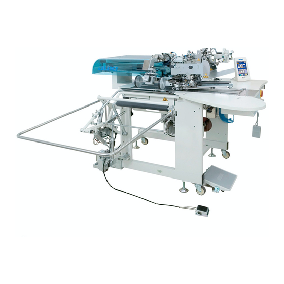
- Page 1 ® Lockstitch, Automatic Welting Machine APW-895 (Parallel Pocket with Flap Sewing) ENGINEER’S MANUAL 40052509 No.E375-00...
- Page 2 PREFACE This Engineer’s Manual is written for the technical personnel who are responsible for the service and maintenance of the machine. The Instruction Manual for these machines intended for the maintenance personnel and operators at an apparel factory contains operating instruction in derail. And this manual describes “Standard Adjustment”, “Adjustment Procedures”, “Results of Improper Adjustment”, and other important information which are not covered in the Instruction Manual.
-
Page 3: Table Of Contents
CONTENTS 1. Specifications ......................1 (1) Machinical specifications ......................1 (2) Electric specifications ......................1 2. Configuration of the machine ................2 3. Standard adjustment ....................3 (1) Machine head .......................... 3 1) How to change the timing belt ......................3 2) Adjustment of needle bar height .....................5 3) Front or rear adjustment of needle bar rocking base ..............5 4) Adjustment of mounting position for needle thread trimming unit ..........7... - Page 4 (3) Optional sections........................59 1) SA-117 (dart stretcher unit) ......................59 2) SA-118 (shim unit) ..........................61 3) SA-119 (suction unit) ........................65 4) SA-120 (automatic interlining feeder unit) ...................71 5) SA-121 (pattern matching marking light unit) ................75 6) SA-127 (suction motor unit) ......................77 7) SP-46 (clamp bar stacker unit) ......................81 8) SP-47 (roller stacker unit) ......................95 4.
- Page 5 11. Air circuit diagram ..................... 202 12. Circuit diagrams ....................203 (1) Block diagram ........................203 (2) Connection diagram ......................204 1) Diagram 1 ............................204 2) Diagram 2 ............................205 3) Diagram 3 ............................206 4) Diagram 4 ............................207...
-
Page 6: Specifications
Machine operation is automatically stopped if the cloth feed mechanism error detector, the needle Safety mechanism thread breakage detector or anu of the various safety devices is actuated. Lubricating oil JUKI New Defrix Oil No. 1 (equivalent to ISO VG7) Grease 1. JUKI Grease A. 2. JUKI Grease B Operating air pressure Standard : 0.5MPa... -
Page 7: Configuration Of The Machine
2. Configuration of the machine The APW-895 consists mainly of the following units. Frame and structural components (Frame sewing table, covers, foot switch, etc.) Clamp foot unit and feed mechanism Corner knife unit Binder unit (Binder components and its driving components) -
Page 8: Standard Adjustment
3. Standard Adjustment (1) Machine head 1) How to change the timing belt Standard Adjustment Flat Arm hole 0.5mm Driving Arm inner diameter Parts no. : 40029049 No. 1 screw Up dead position Flat in Flat front – 3 –... - Page 9 Adjustment Procedures Results of Improper Adjustment 1. Remove the four set screws of the motor. 2. Loosen the two set screws of the coupling. 3. Remove the motor and coupling from the lower shaft 4. Remove the six set screws , and remove the window plate 5.
-
Page 10: Adjustment Of Needle Bar Height
2) Adjustment of needle bar height Standard Adjustment Lower dead point marker of needle bar Blindstitch marker of hook blade tip 3) Front or rear adjustment of needle bar rocking base Standard Adjustment Eccentricity Origin position – 5 –... - Page 11 Adjustment Procedures Results of Improper Adjustment 1. Turn the pulley until the needle bar comes to the lower dead point. 2. Loosen the needle bar connection screw 3. Based on the upper engraved marker line of the needle bar lower dead point, tighten the needle bar connection screw 4.
-
Page 12: Adjustment Of Mounting Position For Needle Thread Trimming Unit
4) Adjustment of mounting position for needle thread trimming unit Standard Adjustment Clearance 30 to 32mm 5) Adjustment of needle thread trimmer sharpness Standard Adjustment 6) Replacement of needle thread knife Standard Adjustment Same surface – 7 –... - Page 13 Adjustment Procedures Results of Improper Adjustment The knife is driven by the air cylinder. Therefore, relieve the air pressure before adjustments. 1. Loosen two setscrews and maintain the clearance toward the throat plate at 5mm in the state that the moving knife is advanced to the extreme front.
-
Page 14: Adjusting The Bobbin Thread Trimming Knife
7) Adjusting the bobbin thread trimming knife Standard Adjustment – 9 –... - Page 15 Adjustment Procedures Results of Improper Adjustment 1. How to join the throat plate and the bobbin thread trimming knife (1) Hold the bobbin thread trimming knife perpendicular to the throat plate. Install it to avoid any twisting motion during operation. (2) Loosen the setscrew of the left bobbin thread trimmer and actuate the bobbin thread trimmer knife cylinder...
-
Page 16: Height Adjustment Of Center Knife
8) Height adjustment of center knife Standard Adjustment Knife bar connection Screw hole 0 to 0.3mm 9) Adjustment of center knife link Standard Adjustment Tightening screw hole Level Metal – 11 –... - Page 17 Adjustment Procedures Results of Improper Adjustment Relieve the air pressure during adjustment. 1. Insert a tool from the hole of the knife bar connecting screw and loosen the knife bar connecting setscrew 2. Turn the motor shaft to move the center knife to the lower dead point.
-
Page 18: Adjustment Of Center Knife Motion Stop
10) Adjustment of center knife motion stop Standard Adjustment Coincidence of shaft centers Withdrawn Protruded 11) Timing adjustment of needle and hook Standard Adjustment Needle Blade point Blade point 0 to -0.05mm 0 to 0.03mm – 13 –... - Page 19 Adjustment Procedures Results of Improper Adjustment While the cylinder is withdrawn, the knife bar is in the state of motion. While it is protruded, the knife bar remains in the state of stop. While this cylinder is protruded, confirm that the shaft center of Link A coincides with that of Screw A If no coincidence is perceived, loosen the nut...
-
Page 20: Adjustment Of Clearance Between Needle And Hook
12) Adjustment of clearance between needle and hook 13) Installing and removing of hook 14) Opener adjustment Standard Adjustment – 15 –... - Page 21 Adjustment Procedures Results of Improper Adjustment Adjustment of clearance between needle and hook’s blade point 1. Loosen the setscrews of the hook shaft base on the adjusting side. 2. Move the hook shaft base to the right and left and adjust the clearance between the needle and hook’s blade point to 0 to 0.03mm.
-
Page 22: Wiper Adjustment
15) Wiper adjustment Standard Adjustment – 17 –... - Page 23 Adjustment Procedures Results of Improper Adjustment 1. Positioning adjustment of wiper unit o If the amount of wiper motion is (1) Loosen the wiper unit setscrew to adjust the unit overall so that small, unthreading will be caused the clearance between wiper’s lower end surface C and the head at the sewing start.
-
Page 24: Hook Oil Amount
16) Hook oil amount Standard Adjustment (1) Adjustment of hook oil amount Oil amount Oil splashed decreases Oil amount Minimum increases Maximum (2) Cleaning of the filter section To the hook shaft base Plunger To oil tank (3) Setting for hook oil amount check –... - Page 25 Adjustment Procedures Results of Improper Adjustment (1) Adjustment of hook oil amount 1. Adjust the oil amount by means of the oil amount adjusting screw that is attached to the hook shaft base. 2. When the oil amount adjusting screw is turned clockwise, the oil amount increases.
-
Page 26: Adjustment Of Thread Take-Up Spring
17) Adjustment of thread take-up spring Standard Adjustment 1.When changing the amount of motion for the thread take-up spring Stroke : 14±2mm 2.When changing the strength of the thread take-up spring Thread take-up spring tension: 1mm → 0.25N (25g) Thread take-up spring tension: 1mm →... - Page 27 Adjustment Procedures Results of Improper Adjustment 1. When changing the amount of motion for the thread take-up spring (1) To adjust the right thread take-up spring , loosen the second thread tension setscrew and turn the second thread tension (asm.) to the right and left.
-
Page 28: Adjustment Of Floating Amount Of The Thread Tension Disk
18) Adjustment of floating amount of the thread tension disk Standard Adjustment Same surface – 23 –... - Page 29 Adjustment Procedures Results of Improper Adjustment 1. Standard adjustment is to obtain the same plane where the end surface of the disk floating cylinder and disk floating cylinder fixing are included. 2. The amount of thread tension disk floating is 1.0 to 1.5mm. (1) Remove the fixing plate setscrew of the disk floating cylinder and take out the disk floating unit.
-
Page 30: Adjustment The Bobbin Thread Remaining Amount Detection
19) Adjustment of the bobbin thread remaining amount detection Standard Adjustment 1.Sensor lateral direction Sensor indicator: OFF stability display: Lit in green (Orange unlit) ON stability display: Lit in green and orange (Both unlit or lighting in orange only indicates an unstable condition.) 2.Adjustment of the sensor lateral direction 3.Method of sensor check Groove section... - Page 31 Adjustment Procedures Results of Improper Adjustment 1. Sensor lateral direction (1) Loosen the sensor setscrew , and adjust the lateral direction to the direction of arrow mark. 2. Adjustment of the sensor lateral direction (1) Loosen the setscrew of the mounting plate B, and adjust the sensor lateral direction.
-
Page 32: Lower Shaft Area
20) Lower shaft area Standard Adjustment 1.Adjustment of the lower shaft gear Mounting direction of the spacer B Hook shaft base 2.Replacement of the lower shaft Plunger groove – 27 –... - Page 33 Adjustment Procedures Results of Improper Adjustment 1. Adjustment of the lower shaft gear (1) Pinch the lower shaft gear between Spacer A and Spacer B If there is any rattling in thrust direc- . Press the gear holder in the direction of the arrow (hook shaft tion, the following difficulties may arise: base side).
-
Page 34: Unit And Related Sections
(2) Unit and related sections 1) Binder adjustments Standard Adjustment When the pedal switch is trodden on to the third grade, the air cylinder begins to be driven and the binder lowers to the section between the right and left clamp foot. After the completion of sewing and corner knife actuation, the binder is raised at the end of backward return by the return action of the air cylinder until its original position is recovered. - Page 35 Adjustment Procedures Results of Improper Adjustment 1. Adjustment of parallelism between slide base side face and machine head side face (1) In the first place, loosen the fixing screw of the lock base Since then, deflect the entire slide base in the direction of the arrow, around the center of the pivot shaft , in order to secure the...
- Page 36 Standard Adjustment 2. Adjustment of binder fall position When the stitch width is 10mm 10mm 0.5 to 1.0mm Binder Sewing table Binder fulcrum shaft Sewing machine needle ± 0.5mm BINDER_FITING_BASE – 31 –...
- Page 37 Adjustment Procedures Results of Improper Adjustment 2. Adjustment of binder fall position (1)Turn off the power supply. Push the binder by hand in the direction of the arrow to lower the binder (2) The sewing machine needle shall be regarded as a standard. The condition is regarded as normal if the binder lowers to the symmetrical position of right and left where the welting patch scale...
- Page 38 Standard Adjustment 3. Adjustment of concentricity between 4. Adjustment of binder levelness pocket bag scale and needle center 5. Adjustment of materials guide 0.5 to 1.0mm 0.1 to 0.6mm – 33 –...
- Page 39 Adjustment Procedures Results of Improper Adjustment 3. Adjustment of concentricity between welting patch scale and needle center (1) After the fixing screw has been loosened, let the entire binder deflect in the direction of the arrow to secure the concentricity of the needle center.
-
Page 40: Clamp Foot Operation
2) Clamp foot operation Standard Adjustment Unilateral/bilateral welt Unilateral/bilateral welt changeover cylinder changeover cylinder Slide base Folding cylinder Folding cylinder Flap presser Flap presser – 35 –... - Page 41 Adjustment Procedures Results of Improper Adjustment 1. By the action of the right-side clamp foot cylinder caused by pedal switch tread-on operation, the right-side clamp foot lowers. When the left-side clamp foot cylinder is actuated, the left-side clamp foot lowers to complete the garment body clamp. 2.
-
Page 42: Tension Adjustment Of Clamp Foot Feed Belt
3) Tension adjustment of clamp foot feed belt 4) Stop position adjustment for forward end or backward end of clamp foot feed Standard Adjustment 3) Tension adjustment of clamp foot feed belt ± 10.2 0.98N 9.4mm 4) Stop position adjustment for forward end or backward end of clamp foot feed 155mm 315mm Forward end position... - Page 43 Adjustment Procedures Results of Improper Adjustment 3) Tension adjustment of clamp foot feed belt 1. Loosen the lock nut , and adjust the tension with the tension screw 2. When a pressing force of 10.2± 0.98N is applied to the center of the pulley, exert a tension to a degree where a deflection of 9.4mm is caused.
-
Page 44: Positioning Adjustment Of Welting Patch Folding Plate
5) Positioning adjustment of welting patch folding plate 6) Adjustment of parallelism of welting patch folding Standard Adjustment Positioning adjustment of welting patch folding plate Sewing machine needle Right folding plate Left folding plate 1.5 to 2.0mm 1.5 to 2.0mm 6) Adjustment of the parallelism of welting patch folding Position of 220mm movement –... - Page 45 Adjustment Procedures Results of Improper Adjustment Positioning adjustment of welting patch folding plate 1. If the dimension is inadequate as illustrated, loosen the setscrew and move it in the direction of the arrow for adjustments. 6) Adjustment of the parallelism of welting patch folding 1.
-
Page 46: Positioning Adjustment Of Right And Left Garment Body Clamp
7) Positioning adjustment of right and left garment body clamp 8) Adjustment of parallelism of right and left garment body clamp and welting patch scale Standard Adjustment 7) Positioning adjustment of right and left garment body clamp ± 0.2mm ± 0.2mm 8) Adjustment of parallelism of right and left garment body clamp and welting patch scale –... - Page 47 Adjustment Procedures Results of Improper Adjustment 7) Positioning adjustment of right and left garment body clamp If the dimensions as specified in the illustration are not secured: For bilateral type, adjust it by turning the ratchet knob For unilateral type, adjust it by turning the ratchet knob 8) Adjustment of parallelism of right and left garment body clamp and welting patch scale 1.
-
Page 48: Adjustment Of Released Presser Height
9) Adjustment of released presser height 10) Positioning adjustment of the flap presser 11) Positioning adjustment of flap scale and flap stopper Standard Adjustment 9) Adjustment of released presser height Garment body clamp Top surface of sewing table 10) Positioning adjustment of the flap presser ±... - Page 49 Adjustment Procedures Results of Improper Adjustment 9) Adjustment of released presser height 1. If the dimensions is not 25 ± 1 mm unlike the drawing, loosen the nut securing the clamp foot cylinder and adjust the screwing amount into the elevating block 10) Positioning adjustment of the flap presser 1.
-
Page 50: Corner Knife Mechanism
12) Corner knife mechanism Standard Adjustment [Corner knife operation] 1. When the corner knife moving motor is turned ON, the moving-side corner knife (position of sewing start) moves to the position that is proportionate to the preset sewing length. 2. At the end of movement, the moving-side corner knife and the fixed-side corner knife (position of sewing end) begin to be raised by the respective elevator air cylinders... - Page 51 Adjustment Procedures Results of Improper Adjustment 1. In the case of corner knife replacement and adjustment, draw out the corner knife unit before adjustments. 2. After completion of the adjustment, be sure to conduct the tests sufficiently to ensure that no defective cutting occurs before regular operation.
-
Page 52: Height Adjustment Of Corner Knife
13) Height adjustment of corner knife 14) Tension adjustment of corner knife feeding belt Standard Adjustment 13) Height adjustment of corner knife 14) Tension adjustment of corner knife feeding belt ± 0.6N Oblong hole Drive-side pulley – 47 –... - Page 53 Adjustment Procedures Results of Improper Adjustment 13) Height adjustment of corner knife 1. Make adjustments by loosening the fixing screw so that the tips of both moving and fixed corner knifes are positioned about 4.5 to 5.5mm from the table upper face to the knife holder upper face at the rising end of the corner knife elevator cylinder, as illustrated.
-
Page 54: Adjustment Of Origin Position Of Corner Knife
15) Adjustment of origin position of corner knife Standard Adjustment [Origin position of the moving and counter corner knife] ± Needle center ± ± ± Gauge size (mm) Assemblying dimensions (mm) 131.5 126.9 125.3 123.8 122.4 Assemblying dimensions (mm) 31.9 41.2 44.3 47.4... - Page 55 Adjustment Procedures Results of Improper Adjustment 1. If the dimensions as specified in the illustration are not secured, loosen the setscrew for adjustment. 2. If the dimension of the fixed corner knife cannot be secured even after the adjustment by loosening the setscrew , try to loosen the setscrew for another adjustment.
-
Page 56: Centering Adjustment Of Corner Knife
16) Centering adjustment of corner knife 17) Adjustment of corner knife right and left bends Standard Adjustment 16) Centering adjustment of corner knife Needle center Sewing machine needle Movement of 220mm Locus of corner knife movement ± A deflection of 0 0.5mm per movement of 220mm 17) Adjustment of corner knife right and left bends Failure... - Page 57 Adjustment Procedures Results of Improper Adjustment 16) Centering adjustment of corner knife 1. The center of corner knife movement is required to coincide with the needle center. 2. This adjustment has been already finished at the time of shipment from the factory. However, in such a case when the corner knife unit is moved for reasons of external shocks or others, some adjustments are needed in the steps described below so that deviation from the needle center can be kept within 0 ±...
-
Page 58: Adjustment Of Parallel Sewin
18) Adjustment of parallel sewin 19) Fine adjustments for stitches Standard Adjustment 18) Adjustment of parallel sewin Approx. 25mm Corner knife Blade tip G: Needle width Knife holder groove section 19) Fine adjustments for stitches – 53 –... - Page 59 Adjustment Procedures Results of Improper Adjustment 18) Adjustment of parallel sewin 1. ecure the corner knife holder with setscrew cso that the opening amount of the holder is set to approx. 25 mm. 2. Insert the corner knife in the groove section of the corner knife holder and secure the blade position where the width of the blade tip attains an approximate needle size G.
-
Page 60: Pedal And Related Sections
20) Pedal and related sections Standard Adjustment – 55 –... - Page 61 Adjustment Procedures Results of Improper Adjustment 1. Adjustment of pedal ball plunger (1) Loosen the pedal ball plunger fixing nut and adjust the position of the pedal ball plunger in the arrow direction (A or B). The pedal click is strengthened when the pedal ball plunger moved in Direction A.
-
Page 62: Marking Light And Related Sections
21) Marking light and related sections Standard Adjustment 1. Adjustment of laser beam parallelism of the marking light Sewing machine needle 80mm Movable range of 220mm Deviation in right and Parallelism not secured left directions Fig. B Fig. A Sewing machine Sewing needle machine... - Page 63 Adjustment Procedures Results of Improper Adjustment 1. Adjustment of laser beam parallelism of the marking light (1) Adjustment of the horizontal line If parallelism of the laser beam is not secured, loosen the setscrew and turn the marking light A for adjustment.
-
Page 64: Optional Sections
(3) Optional sections 1) SA-117 (dart stretcher unit) Standard Adjustment 1. Installation 2. Adjustment – 59 –... - Page 65 Adjustment Procedures Results of Improper Adjustment 1. Installation (1) Install the darts stretcher unit on the base by means of two setscrews (2) Insert the tube in Joint A and the tube in Joint B. 2. Adjustment (1) Loosen and adjust the adjusting screw until the darts holding rubber fits the sewing table hole –...
-
Page 66: Shim Unit)
2) SA-118 (shim unit) Standard Adjustment 1. Installation of the shim bracket – 61 –... - Page 67 Adjustment Procedures Results of Improper Adjustment 1. Secure the shim bracket (40028198) to the shim base (40026610) with the 2 screws (SL6051692TN) 2. Secure the cylinder (PA1500505A0) to the pocket bag clamp cylinder bracket (40034466) with a screw and tighten the pocket bag clamp cylinder rod (40034467) onto the cylinder shaft.
- Page 68 Standard Adjustment Adjustment of interlining clamp parallelism – 63 –...
- Page 69 Adjustment Procedures Results of Improper Adjustment 9. Divide the piping from the one-touch joint (PJ308040002) into two piping systems: one goes to the cylinder B system and the other goes to the cylinder A system Connect the tube of the one-touch joint to the union 10.
-
Page 70: Suction Unit)
3) SA-119 (suction unit) Standard Adjustment – 65 –... - Page 71 Adjustment Procedures Results of Improper Adjustment Suction unit and related sections (setup) 1. Fasten the suction base mounting plate B to the main body frame by means of the setscrews (8 pcs.) on the right and left of the frame. 2.
- Page 72 Standard Adjustment Section A – 67 –...
- Page 73 Adjustment Procedures Results of Improper Adjustment 6. Fix the gasket and the hose base to the suction base means of the setscrew and the washer The worker side should be fixed with the stud . This work shall be done both on the right and left. 7.
- Page 74 Standard Adjustment Section A Section B – 69 –...
- Page 75 Adjustment Procedures Results of Improper Adjustment Adjustment of suction force 1. The suction force is controlled in conjunction with the amount of opening at Section A of the hole of the filter box 2. Manually adjust the suction control plate in the direction of the arrow.
-
Page 76: Automatic Interlining Feeder Unit)
4) SA-120 (automatic interlining feeder unit) Standard Adjustment 1. Installation of the automatic interlining feeder unit Parallelism need be secured 2. Installation of the guide plate Clearance – 71 –... - Page 77 Adjustment Procedures Results of Improper Adjustment 1. Installation of the automatic interlining feeder unit (1) Install the automatic interlining feeder unit on the suction base (2) Fix the automatic interlining feeder unit to the tap of the boss of the suction base by means of two setscrews (3) At the time of installation, the automatic interlining feeder unit shall be installed in parallel to the suction base...
- Page 78 Standard Adjustment 3. Installation of the interlining roll guide Interlining roll 4. Air tube piping Roller release cylinder Interlining cut cylinder Plug Speed controller Interliningl feed cylinder Speed controller – 73 –...
- Page 79 Adjustment Procedures Results of Improper Adjustment 3. Installation of the interlining roll guide (1) Adjust the interlining guide and the thrust collar so that the interlining (interlining roll) can be pulled out straightforward. 4. Air tube piping (1) Make air tube wiring as illustrated. –...
-
Page 80: Pattern Matching Marking Light Unit)
5) SA-121 (pattern matching marking light unit) Standard Adjustment 1. Adjustment of pattern matching marking light position Sewing machine needle Rear horizontal lines for 55mm pattern matching Vertical lines for pattern matching 150mm 150mm Front horizontal lines for pattern matching –... - Page 81 Adjustment Procedures Results of Improper Adjustment 1. Adjustment of the horizontal line When horizontality of horizontal lines is not secured (1) For front horizontal lines, loosen the setscrew and turn the marking light A for adjustment. (2) For rear horizontal lines, loosen the setscrew and turn the marking light B for adjustment.
-
Page 82: Suction Motor Unit)
6) SA-127 (suction motor unit) Standard Adjustment 1. Installation of suction motor unit 2. Suction switch mounting Switch wiring Provisions of "Character +" notches (For cord passing holes) Draw-out cord of the blower motor Green/yellow wire Green/yellow wires only shall be folded back toward the outside. - Page 83 Adjustment Procedures Results of Improper Adjustment 1. Installation of suction motor unit (1) Install the blower joint on the suction motor (2) Install the suction motor on the suction motor mounting plate by means of the setscrews , washers , cushions , and rubber .
- Page 84 Standard Adjustment 3. Installation of the suction motor 4. Installation of the suction pipe 5. Suction pipe fixing 6. Suction wiring – 79 –...
- Page 85 Adjustment Procedures Results of Improper Adjustment 3. Installation of the suction motor (1) Fix the suction motor to the suction unit mounting plate means of the setscrews (6 positions). (Refer to the illustration for the setscrew position.) 4. Installation of the suction pipe (1) Install the suction pipe on the blower joint A section by means...
-
Page 86: Clamp Bar Stacker Unit)
7) SP-46 (clamp bar stacker unit) Standard Adjustment 1. Installation of the clamp bar stacker 30.5mm 2. Stacker support plate and stacker positioning bolt positions 3. Stacker unit assembly – 81 –... - Page 87 Adjustment Procedures Results of Improper Adjustment 1. Installation of the clamp bar stacker (1) Let the stacker base fit the frame and fix it with the setscrews and the washers (in 3 positions). (2) Determine the fixing size so that the end face of frame’s vertical strut and that of the stacker base are separated by 30.5mm, as illustrated.
- Page 88 Standard Adjustment 4. Installation of the air pipe and the cable 5. Adjustment of parallelism between wipe-out bar and sewing table end face Sewing table end face Parallel Parallel Parallel Top surface of sewing table Parallel – 83 –...
- Page 89 Adjustment Procedures Results of Improper Adjustment 4. Installation of the air pipe and the cable (1) Remove the air pipe stop plug and insert the air pipe (Air pipe No. 1 ) (2) Insert the stacker cable in Section A. 5.
- Page 90 Standard Adjustment 6. Adjustment of stacker hinge length 7. Adjustment of stacker close/open sensor position 8. Installation of the safety bar – 85 –...
- Page 91 Adjustment Procedures Results of Improper Adjustment 6. Adjustment of stacker hinge length (1) Adjust the hook section of the stacker fixing hinge so that the stacker unit is firmly fixed by the stacker fixing hinge in the state that it is keeping contact with the stacker positioning bolt. (2) Loosen the nut that is used to fix the hook section and move it...
- Page 92 Standard Adjustment 9. Auxiliary table and cushion assembly and position adjustments 10.Clamp bar cord fixing 11. Overall stacker position check – 87 –...
- Page 93 Adjustment Procedures Results of Improper Adjustment 9. Auxiliary table and cushion assembly and position adjustments (1) If the frame interferes with the right and left ends of the material wipe-out bar , attach an accessory cushion to the section of interference.
- Page 94 Standard Adjustment 12.Adjustment of clamp base position ± 2.5mm 13.Adjustment of second clamp bar position ± 2.5mm 367mm – 89 –...
- Page 95 Adjustment Procedures Results of Improper Adjustment 12. Adjustment of clamp base position (1) Adjust the clamp base position to set the distance between the clamp to 83 ± 2.5 mm and 167 ± 2.5mm. base and stacker base E (2) Loosen the cylinder rod fixing nut , rotate the 2nd clamp bar drive cylinder rod , and move the rod in the arrow direction to make...
- Page 96 Standard Adjustment 14.Adjustment of first clamp bar position 202mm 15.Adjustment of material wipe-out bar position ± 2.5mm – 91 –...
- Page 97 Adjustment Procedures Results of Improper Adjustment 14. Adjustment of first clamp bar position (1) The first clamp bar shall be capable of clamping a piece of cloth (at Section A) when the first clamp bar drive cylinder is withdrawn and it keeps contact with the clamp base cushion in parallel to it. (2) Turn and adjust the first clamp bar cylinder rod by loosening the first clamp bar drive cylinder tip rod fixing nut...
- Page 98 Standard Adjustment 16.Adjustment of clamp stacker unit position 220mm 17.Adjustment of clamp base cylinder air pressure – 93 –...
- Page 99 Adjustment Procedures Results of Improper Adjustment 16. Adjustment of clamp stacker unit position (1) For stacker unit adjustments, vertically move and adjust the base collar by loosening the setscrew so that a dimension of 47mm can be secured between the upper face of the sewing table and that of the clamp base cushion.
-
Page 100: Roller Stacker Unit)
8) SP-47 (roller stacker unit) Standard Adjustment 1. Adjustment of roller stacker setup 0.5mm 2. Right/left adjustment of the rubber roller Shaft flatness 3. Adjustment of backlash – 95 –... - Page 101 Adjustment Procedures Results of Improper Adjustment 1. Adjustment of roller stacker setup (1) Parallelism check Confirm that the stacker table and the rubber roller are mounted in parallel to each other. If the parallelism is not secured, adjust it by loosening four setscrews (2) Clearance check Confirm that a clearance of about 0.5mm is secured between the stacker table...
-
Page 102: Operation Panel And Related Parts
4. Operation panel and related parts (1)Configuration of IP-310 (Front) (Right side) Symbol Name Description TOUCH PANEL,LCD display section Changeover of the data input screen and the sewing READY key screen can be performed. Changeover of the data input screen and the information INFORMATION key screen can be performed. -
Page 103: Memory Switch
(2) Memory switch 1. Changing procedure of the memory switch data (1) Display the memory switch data list screen Press MODE CHANGE-OVER key and the memory switch button is displayed. When this button is pressed, the memory switch data list (screen A) is displayed. (2) Select the memory switch button you desire to change Press UP/DOWN SCROLL button and select DATA... -
Page 104: Memory Switch Data List
(3) Memory switch data list • Level 1 Memory switch data (level 1) are the motion data the sewing machine has in common and the data that operate on all sewing patterns in common. Setting range Item Initial value Edit unit Change-over of the position of clamp foot after sewing end - - - - - -... - Page 105 Setting range Item Initial value Edit unit Stacker timer 3 0.00 to 9.99 0.70 sec. Motion time of material sweeping bar is set. * It is possible to set only when clamp bar stacker option is used. 0.01 sec. Stacker timer 4 0.00 to 9.99 0.00 sec.
- Page 106 Setting range Item Initial value Edit unit Thread breakage detection - - - With/without thread breakage detection is selected. With thread Without thread breakage detection breakage detection Flap presser motion mode - - - Motion order of flap presser is selected. From right From left Right/Left at the...
- Page 107 Setting range Item Initial value Edit unit Condensation/back tuck detailed setting - - - Detailed setting “Perform/Not perform” of pitch of condensation/back tack section is selected. Perform Not perform Flap stopper position 80.0 to 280.0 80.0mm In case of flap sewing start irradiation position of marking light (distance from needle) is set 0.1mm * Setting is only the irradiation position of marking light.
- Page 108 • Level 2 Memory switch data (level 2) are the motion data that the sewing machine has in common and the data that operate on all sewing patterns in common. The data are for the maintenance personnel and possible to edit by pressing the mode switch as long as 6 seconds.
- Page 109 Setting range Item Initial value Edit unit Change-over of flap concealed stitching data edit reference - - - - - - Making the flap concealed stitching data that is set from panel the compensation value from the flap detecting end or the distance from detecting sensor to sewing start is selected.
- Page 110 Setting range Item Initial value Edit unit Selection of mode change-over button display in the pattern list screen - - - Mode change-over button is displayed in the pattern list screen and data of different mode can be selected. Non-display Display Feeding length after sewing endless zipper 0 to 100...
-
Page 111: Optional Setting List
(4) Optional setting list By setting the optional mounted state, it is possible to perform the respective optional operations. Setting range Item Initial value Edit unit Clamp bar stacker mounting/not mounting is set - - - Not mounting Mounting Not mounting Roller stacker mounting/not mounting is set. -
Page 112: Supplemental Remarks Of Each Function Number And Explanation Of Each Function
5. Supplemental remarks of each function number and explanation of each function (1) Version display 1. To display the version information screen: Hold down the key for 3 seconds to call up the version information button, A on the screen. Press this button to display the version information screen. -
Page 113: Keylock Setup
(2) Keylock setup 1. To call up the keylock screen: Hold down the key for 3 seconds to call up the keylock button, A on the screen. Press this button to display the keylock setting screen. The current status appears on the keylock button. : Keylock is inactivated. -
Page 114: Communication Screens Of The Maintenance Personnel Level
(3) Communication screens of the maintenance personnel level The data types allowed to be handled in the communication screens can differ according to the ordinarily used levels and the specific levels that are used by the maintenance personnel. 1. Types of data that can be handled In addition to the four ordinary data types, the five more data types can be used for the maintenance personnel level. - Page 115 2. Reading/Writing of adjustment data and all sew- ing machine data (1) Display of the communication screen of the main- tenance personnel level When the key A is continuously pressed for 3 seconds, the top left image is turned into the orange color (B) and a communication screen of the mainte- nance personnel level is displayed.
- Page 116 (3) Program rewrite start When the start of communication button H is pressed, program rewriting is started. (Caution) Never turn off the power or open/shut the media cover during the work. Otherwise, the main body can be destroyed. Data deleting screen Data writing screen Ending screen When the ending screen is displayed, the replacement...
- Page 117 4. Use of media other than those packed together When the contents of the media card packed together are going to be copied on another media card, the media card of the copying destination should be formatted with IP310. Since then, the following directory configuration should be established with a personal computer.
-
Page 118: Information Screen At The Maintenance Personnel Level
(4) Information screen at the maintenance personnel level 1. Error history (1) To display the information screen at the mainte- nance personnel level: Hold down the information key, A for approx. 3 seconds in the switch sheet section on the data in- put screen to call up the information screen at the maintenance personnel level. - Page 119 2. Cumulative operating information (1) To call up the information screen at the mainte- nance personnel level: Hold down the information key , for approx. 3 seconds in the switch sheet section on the data in- put screen to call up the information screen at the maintenance personnel level.
-
Page 120: Check Program
(5) Check program 1. Display the check program menu screen. When the key is kept pressed for 3 seconds, the check program button A is displayed on the screen. When this button is pressed, the check program menu screen is displayed. –... - Page 121 The check program offers 13 functions as specified below. Pictograph Description Independent head operation Carry out independent head operation. Used to check shuttle oil amount and others. Center knife check Check the independent motion of the center knife motor and the elevating conditions of the center knife.
- Page 122 1. How to use the check program (1) IO1 head aging mode Press the head aging button A of the check program menu screen and display the head aging screen. B : Set up the head rpm value. C : Set up the revolving time. D : Set up the stop time.
- Page 123 (2) IO2 center knife check mode Press the center knife check button A of the check program menu screen and display the center knife check screen. B : Set up the rpm value of the center knife motor. C : Make center knife rise/lower changeover. D : Start the revolution of the center knife motor.
- Page 124 (3) IO3 flap sensor adjusting mode Press the flap sensor adjusting button A of the check program menu screen and display the flap sensor adjusting screen. (Caution) First of all, adjustment of the origin is needed for the marking light. 1) When the flap sensor adjusting screen is opened, the marking light moves to the flap sensor adjusting position.
- Page 125 (4) IO4 reflection seal deterioration detection mode Press the reflection seal deterioration detection button A of the check program menu screen and display the reflection seal deterioration detection screen. When B is pressed, the large presser begins to advance at a low speed. In this phase, detect reflection of the reflection seal by means of the flap sensor.
- Page 126 (5) IO5 stacker adjustments Press the stacker adjustment button A of the check program menu screen and display the stacker adjustment screen. When the B is pressed, the stacker preset by optional setup is actuated. Use Stacker Timer 1 for the pattern that is selected at present.
- Page 127 (6) IO6 unit aging Press the unit aging button A of the check program menu screen and display the unit aging screen. When the B is pressed, the repeated sewing operation is performed for the pattern that is selected at present. When the C is pressed, no unit aging is carried out, but the check program menu screen is recovered.
- Page 128 (7) IO7 input check Press the input check button A of the check program menu screen and display the input check screen. The present input status is displayed. If there is any change in the input status, the panel buzzer sounds and the screen simultaneously changes as illustrated at left.
- Page 129 Name Descriptions IN00 CN30-2 AIR SW Air detection IN12 CN39-24 STOP STATE Sewing machine operation signal IN14 CN39-27 UDET UDET IN15 CN39-26 DDET DDET IN16 CN39-20 PDET PDET IN17 CN39-3 AUDET AUDET IN18 CN39-23 BRK IN24 CN52-13 OP MOTOR Detection of option motor connection IN25 CN44-29 TENTION SW Tension SW with a zipper...
- Page 130 Name Descriptions IN62 C62B-2 CN KN DRWSW Corner knife drawer detection IN64 CN64B-2 BREM L Bobbin thread remaining amount detection, left IN65 CN65B-3 START SW Start switch IN67 CN67B-1 TC PEDAL SW Touch pedal switch IN68 CN68B-1 FLP CLP PDL Flap clamp pedal SW IN69 CN69B-1 STOP SW...
- Page 131 (8) IO8 output check Press the output check button A of the check program menu screen and display the output check screen. With the B button, output check is finished and the check program menu screen is recovered. When the button is pressed, the output status ON/ OFF can be changed.
- Page 132 Descriptions Right clamp foot, fall Right clamp foot, rise Left clamp foot, fall Left clamp foot, rise Folding plate, right Folding plate, left Flap presser, right Flap presser, left Garment body clamp, right Garment body clamp, right Garment body clamp, left Garment body clamp, left Binder, fall Binder, rise...
- Page 133 (9) Touch panel correction 1. Display of the touch panel correction screen When the touch panel correction button A of the check program screen is pressed, the touch panel correction screen is displayed. 2. Pressing the bottom left position Press the red circle C located at the bottom left of the screen.
- Page 134 4. Pressing the top left position Press the red circle E located at the top left of the screen. To complete correction, press the cancel button 5. Pressing the top right position Press the red circle F located at the top left of the screen.
- Page 135 (10) LCD check 1. Display of the LCD check screen When the LCD check button A is pressed on the check program screen, the LCD check screen is displayed. 2. Confirmation of LCD dot missing The LCD check screen is displayed only in one color. In this state, the LCD should be checked to freedom from dot missing.
- Page 136 (11) I11 needle entry position check Press the needle entry position check button of the check program menu screen and display the needle entry position check screen. With the B button, output check is finished and the swing clamp position is moved. With the C button, folding plate operation setup is carried out.
- Page 137 (12) I12 binder elevation Press the binder elevation button A of the check program menu screen and display the binder elevation screen. With the B button, the binder is raised. With the C button, the binder is lowered. With the D button, the binder’s reduced pressure is raised.
- Page 138 (13) I13 head stop angle adjustment Press the head stop angle adjustment button of the check program menu screen and display the head stop angle adjustment screen. With the B button, the upper stop angle is increased by one degree. (10 degrees max.) With the C button, the upper stop angle is decreased by one degree.
-
Page 139: Pedal Volume Adjustments
(6) Pedal volume adjustments 1. 7-step pedal adjustments (1) Display the pedal customize screen. When the mode changeover key is kept pressed for 3 seconds, the pedal customize button displayed on the screen changes color from green to light blue. When this button is pressed, the pedal customize screen of the maintenance personnel level is displayed. - Page 140 2. One-shot pedal adjustments One-shot pedal means that each time the pedal is trodden on, the pedal step is advanced. Unlike the 7-step pedal, the status is retained even when the foot is separated from the pedal. To return the step, reverse foot action is taken.
- Page 141 (2) Display the pedal customize screen. When the mode changeover key is kept pressed for 3 seconds, the pedal customize button displayed on the screen changes color from green to light blue. When this button is pressed, the pedal customize screen of the maintenance personnel level is displayed.
-
Page 142: Control Box
6. Control box (1) Description of each constitutive part 1) Function of boards in the control box and installation position This machine is equipped with a control box on the bottom right side of the table. Major functions of each board in the control box and the installation position are as described below. MAIN board asm. -
Page 143: Function Of Int Board (Relay Board) And Installation Position
3) Function of INT board (relay board) and installation position The INT board is installed inside the large presser cover on the upper side of the table and also inside the cover on leg side under the table. This is a relay board that branches the signal line coming from the MAIN board in the control box and connects the branched line to each I/O equipment unit. -
Page 144: Replacement Of Part
(2) Replacement of parts 1) Replacement of fuses The SDC board is provided with two replaceable fuses for power source protection. o F1 fuse 10AT : DC +50V power source protection fuse for large presser motor driving o F2 fuse 5AT : DC +24V power source protection fuse for small pulse motor driving and solenoid valve driving In regard to the fuse mounting position, refer to 2)-2. - Page 145 2. Replacement of SDC board If this board is out of order, errors will occur mainly in the control source voltage and the main shaft motor of the sewing machine. Two replaceable fuses are installed for power source protection. When replacing the fuses, refer to (2) Replacement of parts, 1) Replacement of fuses.
- Page 146 3. Replacement of FLT board If this board is out of order, possible errors will occur in the AC input power supply. In another case, both the SDC board and the MAIN board can be defective at the same time. Note that there are two types of boards according to the power specifications.
- Page 147 4. Replacement of PMDC board (for roller stacker) If this board is out of order, roller stacker revolutions will become abnormal or there will be lack of torque. Make all settings again because all the dip switches are set at OFF if the replacing board is a newly purchased item.
-
Page 148: Description Of Dip Switches
(3) Description of dip switches 1) MAIN board dip switch The dip switch on the MAIN board is used as a functional changeover switch for production. No modification shall be carried out after shipment because all adjustments and other settings are definite and unnecessary to be modified. -
Page 149: Modification Of The Source Voltage Specifications
(4) Modification of the source voltage specifications A changeover setting can be made only for the control box conforming to the specifications of single-phase 100 to120V / 3-phase 200 to 240V. For the source voltage changeover setting, change the changeover terminal connections according to 2) Replacement of boards 3. -
Page 150: Names Of Switches And Switch Sensors And Installation Places
7. Names of switches and switch sensors and installation places Installation places for the respective switches and sensors are as specified below. Name Connector No. Input No. Remarks Photo sensor for binder upper detection INT CN71A IN-41 Micro switch for binder opening detection INT CN68A IN-38 Cylinder sensor for center knife lifting detection... - Page 151 – 146 –...
- Page 152 – 147 –...
- Page 153 – 148 –...
- Page 154 – 149 –...
- Page 155 – 150 –...
-
Page 156: Maintenance
8. Maintenance (1) Machine head maintenance-related matters 1. Waste hook oil (1) When half a volume of oil is collected in the oil can located in the machine bed cover, turn the oil can and discharge the collected waste oil. 2. -
Page 157: Application Of Grease And Locktight
10g tube JUKI Part No.: 40006323 500g (IE-22) JUKI Part No.: 23640204 JUKI Grease B •••• Used, in particular, for the specific areas with highly loaded parts. Important: this grease must be replenished at the specified intervals of period, according to “(4) Grease-up procedures for the specified position.”... -
Page 158: Spots Where Grease • Adhesive Agents Are Used
(3) Spots where grease • adhesive agents are used EXTERIORS A : JUKI Grease A – 153 –... - Page 159 MAIN SHAFT & THREAD TAKE-UP LEVER COMPONENTS A : JUKI Grease A G : Three-Bond 1373N – 154 –...
- Page 160 NEEDLE THREAD TRIMMER COMPONENTS A : JUKI Grease A C : Locktight 242 – 155 –...
- Page 161 THREAD TENSION & WIPER COMPONENTS A : JUKI Grease A – 156 –...
- Page 162 LOWER THREAD COMPONENTS A : JUKI Grease A C : Locktight 242 – 157 –...
- Page 163 CENTER KNIFE COMPONENTS A : JUKI Grease A C : Locktight 242 – 158 –...
- Page 164 LOWER SHAFT COMPONENTS A : JUKI Grease A G : Three-Bond 1373N – 159 –...
- Page 165 HOOK DRIVING SHAFT LEFT COMPONENTS A : JUKI Grease A – 160 –...
- Page 166 HOOK DRIVING SHAFT RIGHT COMPONENTS A : JUKI Grease A – 161 –...
- Page 167 BACK TUCK COMPONENTS A : JUKI Grease A G : Three-Bond 1373N – 162 –...
- Page 168 CLAMP FOOT UNIT 1 B : JUKI Grease B C : Locktight 242 – 163 –...
- Page 169 CLAMP FOOT UNIT 2 B : JUKI Grease B C : Locktight 242 – 164 –...
- Page 170 CLAMP FOOT UNIT 3 B : JUKI Grease B C : Locktight 242 – 165 –...
- Page 171 CLAMP FOOT FEED UNIT B : JUKI Grease B D : Locktight 243 – 166 –...
- Page 172 CONER KNIF UNIT B : JUKI Grease B D : Locktight 243 E : Locktight 277 F : Locktight 641 G : Three-Bond 1373N CORNER KNIF COMPONENTS B : JUKI Grease B – 167 –...
- Page 173 BINDER UNIT B : JUKI Grease B D : Locktight 243 – 168 –...
- Page 174 MARKING LIGHT UNIT B : JUKI Grease B D : Locktight 243 F : Locktight 641 – 169 –...
- Page 175 FRAME AND COVER COMPONENTS (1) B : JUKI Grease B G : Three-Bond 1373N H : Cemedyne Super X Clear – 170 –...
- Page 176 FRAME AND COVER COMPONENTS (2) B : JUKI Grease B – 171 –...
- Page 177 PEDAL SWITCH COMPONENTS B : JUKI Grease B FLAP PATTERN MATCHING MARKING LIGHT UNIT (SA-121) B : JUKI GreaseB – 172 –...
- Page 178 CLAMP BAR STACKER UNIT (SP-46) B : JUKI Grease B G : Three-Bond 1373N – 173 –...
- Page 179 AUTOMATIC INTERLINING FEEDER UNIT (SA-120) B : JUKI Grease B G : Three-Bond 1373N – 174 –...
- Page 180 ROLLER STACKER UNIT (SP-47) B : JUKI Grease B G : Three-Bond 1373N – 175 –...
-
Page 181: Replenishing Grease To The Designated Place
U245 is cleared to “0” after replenishing grease. 2. In regard to the replenishment of grease to the specified spots to be described later, use the accessory grease tube (Juki Grease B) (Part No. 40013640), without fail. CAUTION : To prevent accidents caused by abrupt start of the sewing machine, start the work after turning OFF the power. - Page 182 2. Replenishment of grease to the center knife section (1) Apply Juki Grease A to both guide faces , knife bar metal top , and knife bar metal bottom (2) Knife bar moves up and down by moving cylinder joint up and down in the state that air is not supplied.
-
Page 183: Consumable Replacement Components
(5) Consumable replacement components The components below are the consumable ones. Periodically replace them. o Thread guide felt (Part No. : 40034444) The part where thread presses is worn out and rough motion of thtead is apt to occur unless it is periodicallt replaced. -
Page 184: Error Code List
9. Error code list Error code Pict Description of error How to recover E001 Initialization of EEPROM of MAIN CPU Turn OFF the power E007 Machine-lock Turn OFF the Main shaft of the sewing machine does not rotate due to some power trouble. - Page 185 Error code Pict Description of error How to recover E028 Write error Possible to Data write from server cannot be performed. re-start after reset. E029 Lid media slot is open. Possible to re-start after reset. E030 Needle bar upper position failure Turn the hand Needle bar is out of needle up position.
- Page 186 Error code Pict Description of error How to recover E221 Grease-up error Possible to When number of stitches of operation is reached to 48 million re-start after stitches, sewing impossible start occurs. reset. * After applying grease, it is possible to release when cleaning memory switch Number of stitches of grease-up.
- Page 187 Error code Pict Description of error How to recover E374 Reflecting tape on left-hand side is deteriorated. Possible to re-start after reset. E376 Pedal continuous depressing error Possible to re-start after reset. E377 Center knife upper detection sensor cannot detect. Possible to re-start after reset.
- Page 188 Error code Pict Description of error How to recover E387 Corner knife fixing side top detection error Possible to re-start after reset. E388 Corner knife moving side bottom detection error Possible to re-start after reset. E389 Corner knife moving side top detection error Possible to re-start after reset.
- Page 189 Error code Pict Description of error How to recover E401 Copy disapproved Possible to When trying to perform overwriting copy on the pattern No. which recover with has been already registered CANCEL button. E402 Erasing disapproved Possible to When trying to delete the pattern used in the cycle sewing recover with CANCEL button.
- Page 190 Error code Pict Description of error How to recover E491 Corner knife length is too short. Possible to When knife cannot be entered since the interval of corner knife is re-start after short. reset. E492 L size length is too short. Possible to When sewing cannot be performed since the inputted L size re-start after...
- Page 191 Error code Pict Description of error How to recover E703 Panel is connected to the sewing machine which is not Possible to supposed (Machine type error) re-start after When the machine type between panel and sewing machine is reset. different in the initial communication E704 Inconsistency of system version Turn OFF the...
- Page 192 Error code Pict Description of error How to recover E904 Solenoid power (24V) abnormality Turn OFF the When solenoid power of SERVO CONTROL circuit board power fluctuates more than ± 15% E905 Heat sink temperature for SERVO CONTROL circuit board Turn OFF the abnormality power...
- Page 193 Error code Pict Description of error How to recover E987 Back tuck motor origin retrieval error Possible to re-start after reset. E998 Corner knife stepping motor origin retrieval error Possible to re-start after reset. E999 Marking light motor origin retrieval error Possible to re-start after reset.
- Page 206 MEMO – 201 –...
-
Page 207: Air Circuit Diagram
Part No. Part Name Q’ty 11. Air circuit diagram G56042540A0 FILTER REGULATER ASM PJ309065201 TRIPLE_BRANCH_UNIVERSAL_ELBOW PX950001000 PLUG PJ303060001 STARAIGHT_UNION Part No. Part Name Q’ty  G5458116000 CURLED_TUBE 18038307 WIRE MARK (34) PJ301065201 HALF UNION 6XPT1/4 18038802 WIRE MARK (39) Á 40044823 AIR_GUN 18038901... -
Page 208: Circuit Diagrams
12. Circuit diagrams (1) Block diagram – 203 –... -
Page 209: Connection Diagram
(2) Connection diagram 1) Diagram 1 Signal phase specification power supply connection Power switch 3-phase specification power supply connection Power switch Fan motor Clamp foot driving pluse motor Main shaft servo motor of the sewing machine Servo motor encoder – 204 –... -
Page 210: Diagram 2
2) Diagram 2 – 205 –... -
Page 211: Diagram 3
3) Diagram 3 – 206 –... -
Page 212: Diagram 4
4) Diagram 4 – 207 –... - Page 213 Please do not hesitate to contact our distributors or agents in your area for further information when necessary. * The description covered in this engineer's manual is subject to change for improvement of the Copyright © 2006 JUKI CORPORATION. commodity without notice.