Table of Contents
Advertisement
Integration Guide
™
BACnet
Communication Interface for
™
ReliaTel
Controllers (BCI-R)
C 2010
TRANE
REV 02
2010.04
J3
-MT
U10
A1
BARCODE LABEL
P1
17
X NUMBER LABEL
SAFETY WARNING
Only qualified personnel should install and service the equipment. The installation, starting up, and servicing
of heating, ventilating, and air-conditioning equipment can be hazardous and requires specific knowledge and
training. Improperly installed, adjusted or altered equipment by an unqualified person could result in death or
serious injury. When working on the equipment, observe all precautions in the literature and on the tags,
stickers, and labels that are attached to the equipment.
March 2011
STATUS
MODBUS
SERVICE
TX
RX
6400-2563-01
LED5
LED6
LED7
LED3
LED1
Q9
A1
SW3
SW2
SW1
LED8
0
0
0
X100
X10
X1
IMC
LINK
ADDRESS SETTING
24VAC
- MODBUS +
LINK
TX RX
1-
J2
LED4
LED2
1-
J1
1-
-
-
+
+
1-
LED9
BACNET
+
TERMINATOR
BAS-SVP09B-EN
+
+
J5
-
Advertisement
Table of Contents

Related Manuals for Trane BACnet BCI-R


Summary of Contents for Trane BACnet BCI-R
- Page 1 Integration Guide ™ BACnet Communication Interface for ™ ReliaTel Controllers (BCI-R) 24VAC - MODBUS + STATUS MODBUS LINK SERVICE TX RX C 2010 TRANE REV 02 2010.04 6400-2563-01 LED5 LED6 LED7 LED3 LED1 LED4 LED2 BARCODE LABEL LED8 LED9 BACNET...
- Page 2 © 2011 Trane All rights reserved This document and the information in it are the property of Trane and may not be used or reproduced in whole or in part, without the written permission of Trane. Trane reserves the right to revise this publication at any time and to make changes to its content without obligation to notify any person of such revision or change.
-
Page 3: Table Of Contents
Table of Contents Overview ............. . 4 BACnet Protocol . -
Page 4: Overview
Overview The BACnet Communication Interface for ReliaTel (BCI-R) supports Trane ReliaTel rooftop units that function as part of a BACnet MS/TP communications network. It allows ReliaTel equipment to communicate with a building automation system (BAS) by using the BACnet protocol over an RS-485 MS/TP communications link. -
Page 5: Getting Started
Getting Started This section describes the necessary software, tools, and initial tasks that are required for a successful integration. Required Software and Tools The following are required: • Tracer™ BACnet Setup Tool OR Tracer™ TU Service Tool, version 6.0 or higher •... -
Page 6: Selecting Wireless Communication
Getting Started Selecting Wireless Communication If using a wireless COMM interface (WCI), set the link select switch to IMC as shown in Figure For wiring instructions, refer to the “BACnet Communication Interface for ReliaTel Controllers” , RF-SVN03-EN. Figure 2. Wireless COMM Interface (WCI) BAS-SVP09B-EN... -
Page 7: Configuring The Bci-R
Configuring the BCI-R The BCI-R can be configured using either the Tracer™ BACnet Setup Tool or the Tracer™ TU service tool. Note: The BCI-R controller is fully configured from the factory for use with Tracer SC based systems. Additional configuration, or the use of Tracer TU, is not necessary. Additionally, the BCI-R self-configures itself to match the unit type upon initial power-up. - Page 8 Configuring the BCI-R To connect to Tracer TU: 1. Connect the USB cable directly from the laptop to the BCI-R, or to an equipment control panel USB port connected to the controller. Important: If using a PC with multiple USB ports, connect by using the same process outlined below for the same piece of equipment.
-
Page 9: Understanding The Mac Address And Bacnet Device Id
Understanding the MAC Address and BACnet Device ID MAC Address The MAC address is the rotary dial address. For Trane systems, this address must be between 1 and 127. Although “0,0,0, ” is a valid BACnet address, Trane reserves this address for the Tracer SC controller. - Page 10 Although 999 is possible from the dials, the maximum allowed number by BACnet is 127. The Max Master is not adjustable in Trane SC systems. For example, if the MAC address is 101 and the front-end system has a Max Master value of 100, the device will not be discovered.
-
Page 11: What To Do After Adding Options Or Equipment To The Unit
Configuring the BCI-R What To Do After Adding Options or Equipment to the Unit Restoring the BCI-R controller to factory defaults is necessary if the unit setup has changed after the initial self-configuration process. This process is called “clearing the controller” . For example, an economizer is added to the machine after the initial installation. -
Page 12: Managing Device Units On The Controller Units Screen
Configuring the BCI-R Managing Device Units on the Controller Units Screen The BCI-R device units can be viewed and managed on the Controller Units screen from either the BACnet Setup Tool or Tracer TU. When the BCI-R first powers up, or after the controller has been cleared, a list of points (the role document) is created from the information supplied to the BCI-R from the ReliaTel RTRM module through the Modbus link. -
Page 13: Bci-R Operation
To initiate system control: 1. Make binary output 1 (BO 1), system control command, active. Trane also recommends setting the relinquish default value to active when performing step 1. Note: BO 1 must in service in order to control from a BAS. -
Page 14: Periodic Update Of Bas Values
BCI-R Operation Periodic Update of BAS Values The BCI-R device requires the BAS system to provide a periodic update to the sensor values. This protects against a loss of communication between the BAS and the BCI-R. By BACnet definition, the present value of the object will maintain the last value written to it, regardless of the amount of time that has elapsed since the last write. -
Page 15: Setpoint Calculations
BCI-R Operation • Upon completion of this action, the BCI-R will set the present value of the Diagnostic Reset Command object back to the inactive state. Setpoint Calculations The equipment has the ability to perform two basic control functions: • Space air temperature control •... -
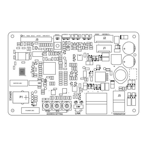
Page 16: Leds And Switches
LEDs and Switches Table 1. Interpreting the LEDs and switches LED type LED activity Indicates... The controller is in boot mode. The controller will be placed into boot mode if the service pin is held in when power is applied. In boot mode, the controller is non-operational and Solid green is waiting for a new main application to be downloaded. -
Page 17: Bacnet Data Points And Configuration Property Definitions
BACnet Data Points and Configuration Property Definitions The BCI-R controller allows a ReliaTel control system to communicate with BACnet systems and devices using BACnet MS/TP . This section includes information about: • BACnet protocol implementation conformance statement (PICS) • Object types: descriptions and configuration (refer to Table 2, p. -
Page 18: Segmentation Capability
BACnet Data Points and Configuration Property Definitions Device Management Description Supported BIBB Device Management-Backup and Restore-B (DM-BR-B) Device Management-Device Communication Control-B (DM-DCC-B) Device Management-Dynamic Device Binding-A (DM-DDB-A) Device Management-Dynamic Device Binding-B (DM-DDB-B) Device Management-Dynamic Object Binding-B (DM-DOB-B) Device Management-List Manipulation-B (DM-LM-B) Device Management-Object Creation and Deletion-B (DM-OCD-B) Device Management-Reinitialize Device-B (DM-RD-B) Device Management-TimeSynchronization-B (DM-TS-B) -
Page 19: Object Types
BACnet Data Points and Configuration Property Definitions Object Types Table 2. Descriptions and configurations Ability Object Ability to Type Required Properties Read Properties Written Optional Properties Read Create Delete Analog • Object_Identifier • Object_Name • Description Yes, only Input • Object_Name •... - Page 20 BACnet Data Points and Configuration Property Definitions Table 2. Descriptions and configurations (continued) Ability Object Ability to Type Required Properties Read Properties Written Optional Properties Read Create Delete Binary • Object_Identifier • Object_Name • Description Yes, only Output • Object_Name •...
- Page 21 Table 2. Descriptions and configurations (continued) Ability Object Ability to Type Required Properties Read Properties Written Optional Properties Read Create Delete Event Log • Object_Identifier • Object _Name • Description Object • Object_Name • Enable • Total_Record_Count (add. 135– • Object_Type •...
-
Page 22: Bacnet Protocol
BACnet Data Points and Configuration Property Definitions BACnet Protocol Data Link Layer Options Supported Data Link Layer Description Option ANSI/ATA 878.1, 2.5 Mb ARCNET (Clause 8) ANSI/ATA 878.1, RS-485 ARCNET (Clause 8), Baud Rate(s) BACnet IP, (Annex J) BACnet IP, (Annex J), Foreign Device ISO 8802-3, Ethernet (Clause 7)(10Base2, 10Base5, 10BaseT, Fiber) LonTalk, (Clause 11), Medium MS/TP Master (Clause 9), Baud Rate(s): 9600, 19200, 38400, and 76800 @1.5% Nominal Baud Rate... - Page 23 BACnet Data Points and Configuration Property Definitions Character Sets Indicates support for multiple characters sets, but does not imply that all character sets are supported simultaneously. Maximum supported string length is 64 bytes (any character set). Character Set Descriptions Supported ANSI X3.4 IBM/Microsoft DBCS ISO 10646 (UCS-4)
-
Page 24: Object Data Points And Diagnostic Data Points
Object Data Points and Diagnostic Data Points For quick reference, the following tables are listed two different ways. Tables 3 through 9 are listed by input/output type and sorted by object identifier. These tables provide the user with the units type for each object type. - Page 25 Object Data Points and Diagnostic Data Points Table 3. Analog Output (continued) Refresh Units of Measure Rate Object Identifier Object Name Description IP/SI Valid Range (Sec.) Sets the equipment exhaust or Analog Output, 33 Exhaust or Return Fan Configuration 1.0 to 255 return fan type.
- Page 26 Object Data Points and Diagnostic Data Points Table 4. Analog Input (continued) Units of Measure Object Identifier Object Name Description IP/SI Exhaust Enable Damper Position Setpoint Exhaust air damper minimum position to enable Analog Input, 71 Percent (98) Status exhaust sequence. Cooling temperature setpoint from space sensor Fahrenheit (64) Analog Input, 74...
- Page 27 2 = Heat Pump 3 = Blower Coil 4 = Unit Ventilator 5 = Fan Coil General description of the equipment-type Multi-State Input, 2 Trane Unit Type 6 = Rooftop classification. 7 = Air Handler 8 = Vertical Self Contained 9 = Unitary...
- Page 28 Object Data Points and Diagnostic Data Points Table 7. Multistate Input (continued) BCI-R Object Object States Identifier Object Name Description *not all states apply to all equipment 1 = Occupied Indicates the current occupancy mode of 2 = Unoccupied Multi-State Input, 20 Occupancy Status the unit.
- Page 29 Object Data Points and Diagnostic Data Points Table 7. Multistate Input (continued) BCI-R Object Object States Identifier Object Name Description *not all states apply to all equipment 1 = Disabled Indicates the operating state of the Multi-State Input, 44 Economizer System Status 2 = Enabled waterside economizer system.
- Page 30 Object Data Points and Diagnostic Data Points Table 9. Binary Input (continued) Object Identifier Object Name Description Object States Indicates the status of the airside economizer Inactive = Disabled Binary Input, 22 Economizer Airside Enable Status system. Active = Enabled Indicates the state of the alarm relay on the Inactive = De-energized Binary Input, 165...
- Page 31 Object Data Points and Diagnostic Data Points Table 10. Diagnostics, Binary Input (continued) Object Identifier Object Name Description Notification Class Binary Input, 246 Diagnostic: Smoke Detector Diagnostic: Smoke Detector 004 – Information Binary Input, 247 Diagnostic: FroStat Trip Diagnostic: FroStat Trip 004 –...
- Page 32 Object Data Points and Diagnostic Data Points Table 10. Diagnostics, Binary Input (continued) Object Identifier Object Name Description Notification Class Binary Input, 295 Diagnostic: Enthalpy Setpoint Fail Diagnostic: Enthalpy Setpoint Fail 004 – Information Diagnostic: Design Min Position at Minimum Fan Diagnostic: Design Min Position at Minimum Binary Input, 296 004 –...
- Page 33 Object Data Points and Diagnostic Data Points Table 11. All Object Types Sorted by Object Name ( ) (continued) Refer to previous tables for detailed descriptions of objects Object Identifier Object Name Description Analog Input, 8 Exhaust Fan Speed Command Indicates the unit commanded exhaust fan speed.
- Page 34 Object Data Points and Diagnostic Data Points Table 11. All Object Types Sorted by Object Name ( ) (continued) Refer to previous tables for detailed descriptions of objects Object Identifier Object Name Description Analog Input, 102 RTDM Minor Version Minor software version number of the RTDM module Analog Input, 99 RTEM Major Version Major software version number of the RTEM module...
- Page 35 Object Data Points and Diagnostic Data Points Table 12. Notification Classes Notification Class Severity Class 001 Critical Class 002 Service Required Class 003 Advisory Class 004 Information Table 13. Diagnostic Objects Sorted by Object Name Object Identifier Binary Input (BI) Object Name Description Notification Class...
- Page 36 Object Data Points and Diagnostic Data Points Table 13. Diagnostic Objects Sorted by Object Name (continued) Object Identifier Binary Input (BI) Object Name Description Notification Class Binary Input, 107 Diagnostic: Entering Evap Temp Sensor Fail Diagnostic: Entering Evap Temp Sensor Fail 002 –...
-
Page 37: Additional Resources
• Tracer™ TU Service Tool Getting Started Guide (TTU-SVN02) (X39641083) • Tracer TU Service Tool for Water-cooled CenTraVac Chillers with Tracer AdaptiView Control Programming Guide (current version of CTV-SVP02) Note: For further assistance, contact your local Trane sales office. BAS-SVP09B-EN... -
Page 38: Glossary
ANSI/ASHRAE Standard 135-2008) An interoperable protocol developed specifically for the building controls industry. The American National Standards Institute named it as a standard, and Trane advocates BACnet protocol for use in system-level control devices. BAS-SVP09B-EN... - Page 39 Glossary BAS-SVP09B-EN...
- Page 40 HVAC systems, comprehensive building services, and parts. For more information, visit www.Trane.com. Trane has a policy of continuous product and product data improvement and reserves the right to change design and specifications without notice. © 2011 Trane All rights reserved...