JRC JSS-2150 Instruction Manual
Mf/hf radio equipment
Hide thumbs
Also See for JSS-2150:
- Instruction manual (248 pages) ,
- Installation manual (114 pages) ,
- Brochure (6 pages)

Related Manuals for JRC JSS-2150


Summary of Contents for JRC JSS-2150
- Page 1 JSS - 2150 2150 MF/HF RADIO EQUIPMENT MF/HF RADIO EQUIPMENT INSTRUCTION INSTRUCTION MANUAL MANUAL WRC-12 WRC-12...
- Page 3 CAUTIONS AGAINST HIGH VOLTAGE Radio and radar devices are operated by high voltages of anywhere from a few hundred volts up to many hundreds of thousands of volts. Although there is no danger with normal use, it is very dangerous if contact is made with the internal parts of these devices. (Only specialists should attempt any maintenance, checking or adjusting.) There is a very high risk of death by even a few thousand volts, in some cases you can be fatally electrocuted by just a few hundred volts.
- Page 4 First aid ☆Note points for first aid Unless there is impending danger leave the victim where he or she is, then begin artificial respiration. Once you begin artificial respiration, you must continue without losing rhythm. (1) Make contact with the victim cautiously, there is a risk that you may get electrocuted. (2) Switch off the machinery and then move the victim away slowly if you must.
- Page 5 ☆If the victim has a pulse but is not breathing (“Mouth to mouth” resuscitation) Figure 1 (1) Place the victim’s head facing backward (place something under the neck like a pillow). (2) Point the chin upward to widen the trachea. (3) Pinch the victim’s nose, take a deep breath, then put your mouth over the victim’s mouth and exhale completely, making sure that your mouth completely covers the victim’s mouth.
- Page 6 ☆ If the victim has no pulse and is not breathing (Heart massage in combination with artificial respiration.) Figure 2 If the victim has no pulse, his or her pupils are dilated, and if you cannot detect a heartbeat, the heart may have stopped, beginning artificial respiration is critical.
-
Page 7: Preface
Preface Thank you for choosing the Model JRC JSS-2150 150W MF/HF radio equipment. This radio equipment can be used as a Global Maritime Distress and Safety System (GMDSS) radio device, compliant with international regulations, that provides emergency communications and standard communications capabilities for small and large ships. -
Page 8: Before Operation
Before operation Concerning the symbols This manual uses the following symbols to explain correct operation and to prevent injury or damage to property. The symbols and descriptions are as follows. Understand them before proceeding with this manual. WARNING Indicates a warning that, if ignored, may result in serious injury or even death. - Page 9 NFC-2150 Antenna tuner NBD-2150 AC/DC Power supply NBB-714/724 Battery charger...
-
Page 10: Handling Precautions
Doing so may save the lives of the crews and passengers on the ship in distress. This equipment is used for both distress communication and routine communication. Contact JRC or our agent if any problem is observed in this unit during routine operation or inspection. - Page 11 CAUTION Do not use this equipment anyplace other than specified. Doing so may cause failure or malfunction. Do not turn the trimmer resistors or the trimmer capacitors on the PCB unit. Doing so may cause failure or malfunction. Do not install the equipment in a place near water or in one with excessive humidity, steam, dust, or soot.
- Page 12 CAUTION DSC messages with incorrect format or data may not be received, but it is not a malfunction. Also if the data terminal is not connected, the equipment does not receive DSC calls requesting ARQ/FEC communication, regardless of either the category of routine, safety, urgency or distress.
- Page 13 CAUTION The print head of the NKG-900 printer may be very hot after printing. Do not touch the print head of the printer. Make sure the print head is cool before replacing the paper or cleaning the print head. Do not use the NKG-900 printer if there is no ink ribbon cartridge or paper. Do not twist the ink ribbon when installing the ink ribbon cartridge.
- Page 14 Sending a Distress Alert CAUTION When sending a distress alert, follow the instructions of the ship's captain or officer in charge. Open the DISTRESS key cover on the NCM-2150 MF/HF CONTROLLER. Press and hold the DISTRESS key for 4 seconds to send the distress alert. When the countdown is finished the screen below on the right is displayed, and after antenna tuning the distress alerts are transmitted.
- Page 15 After receiving acknowledgement, use the radiotelephone to request rescue. First, the responding station calls by radiotelephone. Communicate the following information to that station. Say "MAYDAY". Say "This is (name of your ship)". Tell the station the ship's Maritime Mobile Service Identity (MMSI) number, call sign, ship's position, nature of distress, and rescue requests.
- Page 16 Receiving a Distress Alert WARNING If a distress alert is received, make sure to inform the ship's captain or officer in charge. Doing so may save the lives of the crews and passengers on the ship in distress. When a distress alert is received, the information such as the ID number of the ship in distress and the stage of the distress event are displayed.
-
Page 17: Equipment Exterior
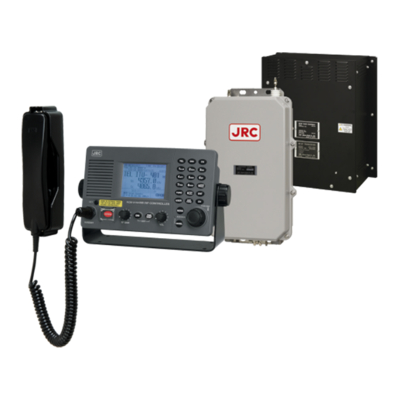
Equipment exterior JSS-2150 150W MF/HF Radio Equipment ● NTD-2150 150W MF/HF Transceiver NFC-2150 Antenna tuner NCM-2150 MF/HF Controller/NQW-261 Handset... - Page 18 NDZ-227 Data terminal / NDF-369 Keyboard NKG-800 Printer...
- Page 19 NKG-900 Printer DPU-414 Printer ● ● NKG-91 Printer NBD-2150 AC/DC Power supply ● ● NBB-714 Battery charger (10A) NBB-724 Battery charger ● ● NCH-321A Distress Message Controller (DMC) ● xvii...
-
Page 20: Table Of Contents
Contents Preface ......................Before operation ..................Handling precautions ................viii DISTRESS ALERTS ..................Equipment exterior ..................Glossary of terms ..................xxii 1. EQUIPMENT OVERVIEW ................ Functions ........................Features ........................Basic configuration ....................1.3.1 DSC model ......................1.3.1.1 Standard components .................. 1.3.1.2 Options ...................... - Page 21 4. OPERATION ..................... Operation overview ....................4.1.1 Operation of the controller ..................4.1.2 Operation of the data terminal ................Basic communications procedure ................4.2.1 Turning on the power ................... 4.2.2 Turning off the power/ Putting into sleep mode ........... 4.2.3 Communicating in radiotelephone mode .............
- Page 22 DSC call log ......................4-55 4.6.1 Received distress messages ................4-55 4.6.2 Received other messages ................... 4-56 4.6.3 Transmitted messages ..................4-56 Display of telex communication logs ................. 4-57 USB memory operation ..................... 4-58 Popup screens ......................4-59 5. SETTINGS & REGISTRATIONS .............
- Page 23 6-12 6.5.5 Regular replacement parts ................... 6-13 7. AFTER-SALES SERVICE ................ 8. DISPOSAL ....................9. SPECIFICATIONS ..................JSS-2150 150W MF/HF Radio Equipment ..............Options ........................Peripheral interfaces ....................10. OPTIONS OPERATION ................. 10-1 10.1 AC/DC power supply (NBD-2150) ................10-1 10.2 Battery charger (NBB-714)
-
Page 24: Glossary Of Terms
Glossary of terms This section defines general and DSC terms related to this equipment. ● General terms AMVER Automated Mutual-assistance Vessel Local time Rescue System MF/HF System that informs another ship of position Medium frequencies and high frequencies of distress ship operated in the United States. (300 kHz to 30 MHz) MMSI Automatic Repeat reQuest... - Page 25 SFEC Selective Forward Error Correction Universal Time Coordinated When broadcasting to a specific group in the VOL (Volume) telex mode, this SFEC is used. Speaker volume SOLAS Convention International Convention for Safety of Life at World Radiocommunication Conference The international convention applies to all Watch Keeping Receiver ships engaged on international voyages.
- Page 26 ・ No reason… No reason Type ・ Congestion… Maritime information Message code indicating the type of the call. exchange center Codes are listed below. congested ・ Individual call… Individual call message ・ Busy… Busy ・ Individual ACK… Acknowledgement ・ Queue… Queued individual call message ・...
-
Page 27: Equipment Overview
Equipment Overview 1. EQUIPMENT OVERVIEW 1.1 Functions This equipment includes MF/HF transceiver, Class-A DSC and DSC watch keeping receiver required as the Global Maritime Distress and Safety System (GMDSS). It is designed as a separated transceiver and small, lightweight controller(s) for easy installation not only in SOLAS Convention ships such as international passenger ships and freight ships of 300 tons or more, but also non-conventional ships of less than 300 tons. -
Page 28: Basic Configuration
Equipment Overview 1.3 Basic configuration 1.3.1 DSC model Standard components Description Model Notes MF/HF transceiver NTD-2150 MF/HF controller NCM-2150 Controller cable 7ZCJD0343 Handset NQW-261 Includes the cradle Antenna tuner NFC-2150 Instruction manual 7ZPJD0699 This manual Options Description Model Notes AC/DC power supply NBD-2150 Battery charger NBB-724... -
Page 29: Dsc/Nbdp Model
DTE cable 7ZCJD0388 For expansion of the controller DTE power cable 7ZCJD0419 Keyboard NDF-369 Mounting bracket MPBP31721 USB memory UDG4-1GAR-JRC Hagiwara Sys-Com / 1GB Printer NKG-800/900 6ZCSC00407 Printer connection cable 7ZCSC0205A/0322B Desktop type Printer power cable 6JNKD00100B Printer paper (100m) -
Page 30: System Configuration
Equipment Overview 1.3.3 System configuration NKG-800/900 Printer NDZ-227 Data terminal NCM-2150 MF/HF Controller NDF-369 Keyboard NQW-261 Handset (DSC/NBDP model only) Expansion Controller NFC-2150 Antenna Tuner NTD-2150 MF/HF Transceiver NCH-321A DMC * The equipment can also be connected to the VDR server to use the remote maintenance system. -
Page 31: External Dimensions
Equipment Overview 1.4 External dimensions Below are the external dimensions of each unit. MF/HF Transceiver (NTD-2150) (1) Unit: mm Weight: Approx. 13 kg MF/HF Controller (NCM-2150) (2) Unit: mm Weight: Approx. 1.4 kg... - Page 32 Equipment Overview Handset (NQW-261) (3) Unit: mm MOUNTING Weight: Approx. 0.5 kg HOLES Connection box (NQD-2250) (4) Unit: mm Weight: Approx. 0.6 kg...
- Page 33 Equipment Overview Antenna Tuner (NFC-2150) (5) Unit: mm Weight: Approx. 3.3 kg Junction Box (NQD-2253) (6) Unit: mm Weight: Approx. 1.2 kg...
- Page 34 Equipment Overview Data Terminal (NDZ-227) (7) Unit: mm Weight: Approx. 4.6 kg Keyboard (NDF-369) (8) Unit: mm Weight: Approx. 0.4 kg...
- Page 35 Equipment Overview Printer (NKG-800) (9) ● Desktop type Unit: mm Weight: Approx. 3.7 kg (10) Printer (NKG-900) ● Desktop type Unit: mm Weight: Approx. 4.8 kg...
- Page 36 Equipment Overview (11) Printer (DPU-414) ● Desktop type Unit: mm Weight: Approx. 0.6 kg (12) Printer (NKG-91) ● Wall mount type WIRING HOLE (SIDE) MOUNTING HOLES Unit: mm Weight: Approx. 1.5 kg WIRING HOLE (BACK) 1-10...
- Page 37 Equipment Overview ● Flash mount type Unit: mm Weight: Approx. 0.8 kg (13) AC/DC Power Supply (NBD-2150) Unit: mm Weight: Approx. 9.8 kg 1-11...
- Page 38 Equipment Overview (14) Battery Charger (NBB-714) Unit: mm Weight: Approx. 8.6 kg (15) Battery Charger (NBB-724) Unit: mm Weight: Approx. 12 kg 1-12...
-
Page 39: Block Diagram
Equipment Overview 1.5 Block diagram 1.5.1 DSC model Rx/WKR Tx antenna antenna JQD-69C Joint box Lead wire RG-12/UY TH-7/1.6 NQW-261 M-P-7 Handset 7ZCJD M-P-7/M-P-5 RX/WKR ANT TX ANT TTYCSLA- 4 M-P-7 M-A-JJ 0343 DPYC-2.5 (5m) RG-10/UY 5D-2VH NCM-2150 MF/HF Controller NTD-2150 NFC-2150 MF/HF Transceiver... - Page 40 Equipment Overview 1.5.2 DSC/NBDP model Rx/WKR Tx antenna antenna JQD-69C Joint box Lead wire RG-12/UY TH-7/1.6 NQW-261 M-P-7 Handset 7ZCJD M-P-7/M-P-5 RX/WKR ANT TX ANT 0343 TTYCSLA- 4 M-P-7 M-A-JJ DPYC-2.5 (5m) RG-10/UY 5D-2VH NCM-2150 MF/HF Controller NTD-2150 NFC-2150 MF/HF Transceiver Antenna tuner TTYCYSLA-4 NQD-2250...
-
Page 41: Names And Functions
Names and Functions 2. NAMES AND FUNCTIONS 2.1 Controller (NCM-2150) The controller parts and their functions are described below. 11 12 1. Internal loud speaker 2. Jack for telegraph in continuous wave (CW) mode 3. Black and white liquid crystal display unit 4. - Page 42 Names and Functions ···· Enter key. ・ USER ···· User defined key. Register a frequently used menu to open it quickly. ・ ···· Tunes the antenna. ・ TUNE ···· Sets the channel input mode (user channel, ITU channel, or free frequency). ・...
-
Page 43: Controller's Display
Names and Functions 2.2 Controller’s display The LCD screen on the controller changes according to current conditions. This section describes the status display, operating display, FUNC menu, and main menu screens. 2.2.1 Status display Occupied mark. Indicates another controller 10. Indicates the frequency (band) the DSC has the access rights. -
Page 44: Operating Display
Names and Functions 2.2.2 Operating display (1) General After setting the frequency, pressing PTT key in TEL mode, sending/receiving messages in DSC/TLX mode, and things like that, the controller shows the operating display as follows. Indicates the MMSI and the latest position Indicates the S meter (or TX meter), and and that time. - Page 45 Names and Functions (2) Operating display of DSC calls When communicating using DSC messages, the controller shows as follows. Indicates the transceiver setting screen Indicates the message info as follows; similar to the status display mentioned Destination/source ID to comm with: above.
-
Page 46: Function Screen And Key Operations
Names and Functions 2.2.3 Function screen and key operations The functions assigned to the number keys are temporarily enabled by pressing the FUNC key in the status display or holding down the FUNC key and pressing the number key. I D 4 3 1 0 0 1 2 3 4 2 3 : 5 9 ( U T C ) P o s 8 9 ゚... -
Page 47: Menu Screen
Names and Functions 2.2.4 Menu screen I D 4 3 1 0 0 1 2 3 4 2 3 : 5 9 ( U T C ) P o s 8 9 ゚ 5 9 . 0 1 2 3 ' N 1 7 9 ゚... -
Page 48: Data Terminal(Ndz-227
Names and Functions 2.3 Data terminal(NDZ-227) This section describes the name of each part in the data terminal and the function. 1. Color liquid crystal display (LCD) unit 2. POWER lamp This lamp lights to green while operating the data terminal, and blinks during the sleep. 3. -
Page 49: Display Of Data Terminal
Names and Functions 2.4 Display of data terminal The content displayed on the LCD screen in the data terminal is different according to the situation. This section describes a regular screen, the telex communication screen, and the message file edit screen. 2.4.1 Regular screen Indicates the guide according to the... -
Page 50: Telex Communication Screen
Names and Functions 2.4.2 Telex communication screen Indicates the operating condition of the Indicates the telex message or the name telex communication from the left of each of the executed function key. segment as follows. Indicates the usable function keys guide. 1)... - Page 51 Names and Functions 2.4.3 Message file edit screen Indicates the state of the edit screen as ・ F6 : follows. ・ F7 :Quit Editing telex file :File name ・ F8 :Save As Line :Line position of cursor ・ F9 :Save & Quit Column :Row position of cursor ・...
-
Page 52: Installation
Installation 3. INSTALLATION CAUTION To install this equipment, contact our service center or agents. Special knowledge on selecting the place where the antenna is to be mounted and setting the ID number (MMSI) assigned to the ship is required in addition to installing the equipment. -
Page 53: Operation
Operation 4. OPERATION This chapter describes basic operations of the controller and the data terminal, radiotelephone communications, telex communications, DSC calling procedures, and other radio functions. Operation overview 4.1.1 Operation of the controller Basically, the controller is operated with the numeric keypad (10key), the MENU key, and the jog dial for other than the telex communication. - Page 54 Operation Menu tree Main Menu Hierarchical Menu 1 Hierarchical Menu 2 Shortcut Key Note MENU+1 ( R T N ) 1. DSC non-distress call FUNC+0 ( Te s t ) 2. DSC drobose call MENU+2 3. Editing a distress msg MENU+3 4.
- Page 55 Operation DSC alarm specifications The following table summarizes the alarm characteristics when communicating particularly in the DSC mode. Reason for the alarm Sound Increase Shutdow n Receiving a new distress Two tones of Manually event 2200Hz(250ms) and 1300Hz(250ms) Acknowledging a received Two tones of Manually distress event...
-
Page 56: Operation Of The Data Terminal
Operation 4.1.2 Operation of the data terminal Basically, the every function concerning the telex mode such as ARQ/FEC communication or scanning can be operated from the data terminal. ● To connect and install the data terminal, setup the 7.6 Option menu of the controller. To set the communicate mode to the telex mode, press the Enter key of the keyboard. - Page 57 Operation Menu tree in data terminal Short-cut Short-cut Main Menu Drop-do wn Ke y Remarks File Edit new file Edit existing file Rename file Delete file Cop y file Initialize USB Remo ve USB Tune Frequency list Printable ITU channel set Tx/Rx frequenc y set Tx tune Scanning start (stop)
-
Page 58: Basic Communications Procedure
The start screen of the data terminal is as shown at right. If errors are detected during the operation check, the message is displayed. Please inform JRC or our agent of the error contents. -
Page 59: Turning Off The Power/ Putting Into Sleep Mode
Operation 4.2.2 Turning off the power/ Putting into sleep mode CAUTION When completely turning off the power to the equipment, turn off the breaker on the transceiver ■ ■ Procedure Press the PW R key and C O N T simultaneously. -
Page 60: Communicating In Radiotelephone Mode
Operation 4.2.3 Communicating in radiotelephone mode Use the handset to communicate in radiotelephone mode. ■ ■ Procedure When operating on a controller without access rights (OCC is displayed), press the jog dial to obtain the access rights. Unless the controller with access rights is being used, the access rights are acquired and the OCC display on the screen disappears. - Page 61 Operation A N T Press the key to tune the antenna. T U N E blinks if the transmission frequency Note is not tuned. Even if is not displayed, tune the antenna before making a call. lights during tuning. It goes out after tuning.
-
Page 62: Communicating In Cw Mode
Operation 4.2.4 Communicating in CW mode Use a CW keyer to communicate in CW mode. ■ ■ Procedure When operating on a controller without access rights (OCC is displayed), press the jog dial to obtain the access rights. Unless the controller with access rights is being used, the access rights are acquired and the OCC display on the screen disappears. - Page 63 Operation Press the A N T key to tune the antenna. T U N E blinks if the transmission frequency Note is not tuned. Even if is not displayed, tune the antenna before making a call. lights during tuning. It goes out after tuning.
-
Page 64: Receiving Am Broadcasts
Operation 4.2.5 Receiving AM broadcasts It is possible to listen to the radio in AM mode. ■ ■ Procedure When operating on a controller without access rights (OCC is displayed), press the jog dial to obtain the access rights. Unless the controller with access rights is being used, the access rights are acquired and the OCC display on the screen disappears. -
Page 65: Communicating In Telex Mode (Tlx)
Operation 4.2.6 Communicating in telex mode (TLX) When communicating in the telex mode, the data terminal is used. In the telex communication, the ARQ (Automatic Repeat reQuest) mode and FEC (Forward Error Correction) mode are available to communicate between two stations and to broadcast respectively. Additionally in the FEC mode, there are two modes of the CFEC (Collective Forward Error Correction) mode for unspecified receivers and SFEC (Selective Forward Error Correction) mode for specified receivers, which are selectable according to the purpose. - Page 66 Operation Select the station to be called with the cursor, and press Enter key. The frequency list of the selected radio station is displayed. If the position of the station is registered, the MUF (maximum usable frequency) is displayed in the lowest line as a reference to select the frequency.
- Page 67 Operation The characters typed with the keyboard can be transmitted in sequence. And all of the characters displayed on the screen are printed out on the printer. In the ARQ mode, it is [ T L X ] T x = 2 1 7 4 . 5 0 k H z / R x = 2 1 7 4 . 5 0 k H z U S B S t a t i o n I D : [ 0 0 4 3 1 0 1 2 3 ] possible to alternate the...
-
Page 68: Cfec Mode Operation
Operation CFEC mode operation ( 1 ) Sending with CFEC Messages can be sent as a broadcast on the selected work frequency using the CFEC mode. ■ ■ Procedure If displaying the message of "Press Enter key to get the access right in the NBDP mode…"... - Page 69 Operation Select Yes and press Enter key to start the call at the selected frequency. Sending the phasing signal is [ T L X ] T x = 2 1 7 4 . 5 0 k H z / R x = 2 1 7 4 . 5 0 k H z U S B started with the CFEC mode.
- Page 70 Operation To finish the communication, press F10 Stop key. After sending the end of [ T L X ] T x = 2 1 7 4 . 5 0 k H z / R x = 2 1 7 4 . 5 0 k H z U S B communication for about five F i l e...
- Page 71 Operation Input the receiving frequency of the CFEC broadcasting, and press Enter key. The antenna is tuned to the frequency and the message as shown at right is displayed. The transmitting frequency is set simultaneously by the above procedure, but in Note this case the frequency is meaningless.
-
Page 72: Sfec Mode Operation
Operation SFEC mode operation Messages can be sent to the specific stations as a broadcast on the selected work frequency using the SFEC mode. Additionally, regarding the SFEC reception, refer to the previous section because it is similar to the CFEC reception. ■... - Page 73 Operation Select the work frequency with the cursor, and press Enter key. The selected frequency is set and the antenna is tuned to the frequency. The message as shown at right is displayed to confirm that the channel is busy. Select Yes and press Enter key to start the call at the selected frequency.
-
Page 74: Editing Telex Messages
Operation Editing telex messages When communicating in the telex mode, the message file can be sent, which is prepared beforehand as follows. ■ ■ Procedure If displaying the message of "Press Enter key to get the access right in the NBDP mode…"... - Page 75 Operation The function keys available for the edit screen and the content are as follows. Note Group 1 ● ・ F1 : Insert On/Off ············· Sets the input condition to the insert mode by pressing it while Insert On is displayed. And sets the input condition to the overwrite mode by pressing it while Insert Off is displayed.
- Page 76 Operation Besides editing messages mentioned above, the following items in the file menu concerning to the message files are available. ・ Rename file ········· Changes the name of the file saved in flash ROM(C:) or USB memory (A:) . Delete file ··········· Deletes the file saved in the flash ROM (C:) or the ・...
-
Page 77: Setting The Radio
Operation 4.3 Setting the radio This section describes how to set the communication frequencies and how to use the receiver and transceiver functions. 4.3.1 Setting the communication frequencies Use the free frequency input mode to input the communication frequencies directly. ■... - Page 78 Operation 4.3.2 Setting the communication channels Besides the free frequencies described previously, ITU channel mode and user channel modes can also be set. The ITU channel mode is mode for using channels based on the international standard and is built-in to the equipment. The user channel mode is the mode for using channels on pre-registered frequencies.
- Page 79 Operation (2) Setting the ITU channels ■ ■ Procedure After setting the TEL, DSC or CW modes, press the key to set the display to the ITU channel mode. Input the channel by using the numeric keypad. When 4 is input using the numeric Note keypad, it appears on the far right as shown in the screen on the right.
- Page 80 Operation (3) Setting user channels A total of 20 groups with 20 channels set to each group (i.e. 400 channels) can be registered on the equipment. This section explains how to set channels that are already registered. Note See "5.4 Registering user channels" for how to register frequencies to user channels. ■...
- Page 81 Select 1. User channel list and press ENT. 5.1)User channel list (index) CH group name Type 01 JRC Tokyo The user channel list index (group list) as Pacific ABC shown at right is displayed. Select the intended channel group and press ENT.
-
Page 82: Setting The Automatic Gain Control (Agc)
Operation 4.3.3 Setting the automatic gain control (AGC) ■ ■ Procedure Press the key, and through MENU 5.4)Receiver hierarchical menus, select 5.4 Receiver. 1.Auto gain control :Slow 2.Noise reduction :OFF 3.Attenuation :OFF 4.Clarifier :+000Hz 5.Squelch :OFF 6.CW bandwidth :Narrow 7.Scan 0.Back Select 1. -
Page 83: Setting The Attenuation (Att)
Operation 4.3.5 Setting the attenuation (ATT) ■ ■ Procedure Press the key, and through MENU 5.4)Receiver hierarchical menus, after 5.4 Receiver 1.Auto gain control :Slow 2.Noise reduction :OFF appears, move the cursor to 3. 3.Attenuation :OFF 4.Clarifier :+000Hz Attenuation. 5.Squelch :OFF 6.CW bandwidth :Narrow... -
Page 84: Setting The Squelch Level
Operation 4.3.7 Setting the squelch level ■ ■ Procedure Press the key, and through MENU 5.4)Receiver hierarchical menus, after 5.4 Receiver 1.Auto gain control :Slow 2.Noise reduction :OFF appears, move the cursor to 5. Squelch. 3.Attenuation :OFF 4.Clarifier :+000Hz 5.Squelch :OFF 6.CW bandwidth :Narrow... -
Page 85: Scanning The Rx Frequencies
5.4.7)Scan Note No CH group name Type by pressing and holding the FUNC 01 JRC Tokyo key and then pressing the Pacific ABC key on the status display. SCAN If the user channel is not registered, scan cannot be done so the screen shown at right is not displayed. - Page 86 Operation Scanning of channels in telex mode ( 2 ) The scanning of channels in the telex mode is started with the data terminal. ■ ■ Procedure If displaying the message of "Press Enter key to get the access right in the NBDP mode…"...
-
Page 87: Reducing The Tx Power
Operation 4.3.10 Reducing the Tx power ■ ■ Procedure Press the key, and through 5.5)Transmitter MENU hierarchical menus, select 5.5 1.Power :High 2.Tune power :Normal Transmitter. 3.Auto tune start :ON 0.Back Select 1. Power and press ENT to move 5.5)Transmitter the cursor to the right, then use the jog dial 1.Power :Low... -
Page 88: Basic Dsc Operations
If no data is shown in the working FRQ field Note just after turning on, please contact JRC or our agency to register the nonvolatile data. In this case, the input MF data is stored temporarily as the volatile data. - Page 89 Operation The operating display is appeared and initiates the DSC call After checking the channel free condition, sends the message and waits for the acknowledgement. During waiting for the acknowledgement, Note the handling menus are available for the following purposes. Note) To focus the cursor on it, use FUNC or CANCEL key to move the...
-
Page 90: Receiving Routine Individual Calls
Operation 4.4.2 Receiving routine individual calls When receiving an individual DSC call from a coast or ship station, according to the message, perform the following procedures as appropriate. ■ ■ Procedure The screen at right is displayed, and the ALM lamp blinks and the alarm grows louder gradually. - Page 91 Operation After sending an acknowledgement, the I D 4 3 1 0 0 1 2 3 4 2 3 : 5 9 ( U T C ) P o s 8 9 ゚ 5 9 . 0 1 2 3 ' N 1 7 9 ゚...
-
Page 92: Routine Group Calls
Operation 4.4.3 Routine group calls For radiotelephone or FEC broadcasting, a DSC routine call to a group of stations is available. ■ ■ Procedure On the menu “1. DSC non-distress call” 1)DSC non-distress call Call type :[RTN/Group/TEL ] mentioned above, set the Call type on the Address Calling FRQ:[ 2177.00kHz] menu shown at right to RTN/Group/TEL or... -
Page 93: Emergency Calls (Dsc Distress/Urgency/Safety Calls)
Operation 4.5 Emergency calls (DSC distress/urgency/safety calls) In emergency, the DSC is available for safety, urgency calls, or distress alerts. For safety and urgency calls, either individual or area calls is selectable for the type of call. For distress alerts, enabled to send either after entering the nature of distress or frequency, or without entering anything. - Page 94 Operation When the acknowledgement is received, the ALM lamp blinks and the alarm starts sounding. After silencing it with CANCEL key, the screen becomes as shown at right. The safety test call process is now complete. However note that even though the call is sent normally, the acknowledgement may not be received from the called station for some reason.
-
Page 95: Receiving Safety Or Urgency Individual Calls
Operation 4.5.2 Receiving safety or urgency individual calls When receiving an individual DSC call from a coast or ship station, according to the message, perform the following procedures as appropriate. ■ ■ Procedure The screen at right is displayed, and the ALM lamp blinks and the alarm grows louder gradually. -
Page 96: Safety Or Urgency Area Calls
Operation 4.5.3 Safety or urgency area calls For radiotelephone or FEC broadcasting, a DSC safety area call can be made as follows. ■ ■ Procedure On the menu 1.DSC non-distress call, set the 1)DSC non-distress call Call type to SAF/Area/TEL or URG/Area/TEL Call type :[SAF/Area/TEL Area form... -
Page 97: Receiving Safety Or Urgency Area Calls
Operation 4.5.4 Receiving safety or urgency area calls ■ ■ Procedure The screen at right is displayed, and the ALM lamp blinks and the alarm grows louder gradually. If no procedure exists, starts operating the received message, i.e. the specified working frequency is set automatically. -
Page 98: Quick Distress Alerts
Operation 4.5.5 Distress alerts When in distress, distress alerts are always transmitted by pressing the dedicated DISTRESS key. The distress alerts transmit your own MMSI, ships position, time of the position, and the nature of distress. CAUTION Do not test the distress alert. Doing so may inconvenience local shipping and rescue centers. - Page 99 Operation After the antenna is tuned, the distress alert is sent. The distress alerts are sent on all 6 distress and safety frequencies. The equipment stays in distress mode until acknowledgement is received or the distress alert cancelling procedure is complete. Unless an acknowledgement is received or the distress alert is cancelled manually, the distress alert repeats automatically in a...
- Page 100 Operation If cancelling the distress alert since a false distress alert is transmitted Note accidentally, perform the distress alert cancelling procedure as follows. Press the CANCEL key while the option selectable screen is focused. On the popup screen, select Continue with the jog dial, and press ENT.
-
Page 101: Distress Alerts From The Menu
Operation Distress alerts from the menu Attention During communicating in telex mode, finish it to enable the menu before practicing below. The following describes the procedure to send a distress alert with the nature of distress selected in the menu. Also, besides manually inputting position and the time information, the subsequent communication mode, the transmission method and frequency can be set here. - Page 102 Operation Press ENT. 3)Editing a distress msg Nature :[Fire The cursor moves to Position. If a valid position Position :[NE] :[ 89゚59.0123'N] and time of that position are already displayed, :[179゚59.6789'E] UTC of pos :[23:59] no entry is necessary. Skip to step 6. Mode(fixed) :[Radiotelephone] Attempt type:[Multi-FRQ ] Tx bands...
- Page 103 Operation If pressing DISTRESS key during the Tx bands settings (before fixing by pressing Note ENT), the distress alerts are sent on the band(s) registered previously. Open the DISTRESS key cover. Press and hold the DISTRESS key for 4 seconds until the countdown is completed.
-
Page 104: Receiving Distress Alerts
Operation Receiving distress alerts When a distress alert is received from another ship, displays the event immediately with the specific two-tone alarm sound. WARNING If a distress alert is received, make sure to inform the ship's captain or officer in charge. Doing so may save the lives of the crews and passengers on the ship in distress. -
Page 105: Distress Relay Calls On Behalf Of Someone Else (Drobose)
Operation with the ship in distress according to the following procedure. Say "MAYDAY". Repeat the identity (MMSI) of the ship in distress 3 times Say "This is..." Repeat the identity (MMSI) of your ship 3 times Say "RECEIVED MAYDAY". Incase of the FEC specified, after sending the acknowledgement the frequency is set to 2174.50 kHz. - Page 106 Operation Input the Distress ID (MMSI) of the ship 2)DSC drobose call Format :[Individual] in distress, Nature, Position and/or UTC, Address :[001234567] Distress ID:[0 if known. Nature :[Undesignated ] Position ゚ The nature of distress is selectable from below. ゚ UTC of pos :[ Nature of distress Contents...
-
Page 107: Dsc Call Log
Operation 4.6 DSC call log DSC messages are classified as received distress messages, received other messages and transmitted messages. The 20 most recent messages for every type are saved in the log. CAUTION Received distress message logs are automatically deleted after 48 hours to avoid accidental resending or other misoperation. -
Page 108: Received Other Messages
Operation 4.6.2 Received other messages Received messages other than the distress (routine, safety, and urgency) are stored in this log. ■ ■ Procedure Press the key, and through MENU hierarchical menus, select “4.2 Received others”. On the bottom line, the MMSI of the ship is displayed highlighted by the cursor. -
Page 109: Display Of Telex Communication Logs
Operation 4.7 Display of telex communication logs The telex communication is saved automatically as the log, and the reference is available later. ■ ■ Procedure If displaying the message of "Press Enter key to get the access right in the NBDP mode…"... -
Page 110: Usb Memory Operation
Operation 4.8 USB memory operation This section describes how to use the USB memory. Attention ・ The following conditions are required for the USB memory. Note) Not all USB memories satisfying the every condition are guaranteed. - The specification is complied with USB 1.1 or USB 2.0 standards. - No USB hub is built-in and is used to connect the USB memory. -
Page 111: Popup Screens
Operation 4.9 Popup screens The contents of the popup screens of the data terminal are as follows (in alphabetical order). Message Buttons Description Is it OK to delete a file? Attention Yes/ No Yes: Deletes the file. Are you sure to erase? Cancels this operation. - Page 112 Operation Message Buttons Description Error The specified file cannot be used for File access failed. any malfunction. Error The file is malformed and invalid. Invalid file. Detected the keyboard I/F ROM Error Keyboard I/F ROM checksum error. checksum error. Error A specified folder is not found.
- Page 113 Operation Message Buttons Description Error The file name extension is allowed only Input “DB” as the correct extension. “DB”. Error The file name extension is allowed only Input “TLX” as the correct extension. “TLX”. The specified file is not found, or Error The file name is wrong.
- Page 114 Operation Message Buttons Description USB memory is being formatted. Formatting the USB memory. ----- Please wait. Wait for a while. It is printing. Now printing. ----- Please wait. Wait for a while. Now reading data. Information on the file and the folder ----- Please wait.
-
Page 115: Settings & Registrations
Settings & Registrations 5. SETTINGS & REGISTRATIONS This chapter describes the procedures for settings and registrations such as manual date and time settings, registration of channels in each mode, advanced DSC settings, printer settings, and other settings for the equipment. 5.1 Date and time settings Normally, the date and time are updated automatically if importing GPS information. - Page 116 Settings & Registrations To input the present time, press ENT. 7.1)Date & time 1.Date :2012-12-31 Input the hours and minutes with the 2.Present time numeric keypad or jog dial, and press 3.Display form - UTC/LT :UTC ENT. - LT diff To close this menu after completing the 0.Back date and time settings, place the cursor...
-
Page 117: Own Ship Position And Time Settings
Settings & Registrations 5.2 Own ship position and time settings Normally, the ship's position and the time are updated automatically if importing GPS information. But, if necessary, input these parameters manually as follows. CAUTION The time in the 7.2 POS/TIME menu means the time when the position information is valid, and is different from the present time mentioned in the 7.1 Date &... -
Page 118: Controller Settings
Settings & Registrations 5.3 Controller settings The following describes the procedure regarding individual settings for the controller such as LCD adjustment. 5.3.1 LCD adjustment The LCD conditions for viewability are adjustable as follows. ■ ■ Procedure Press the key, and through MENU 7.3.1)LCD adjustment hierarchical menus, select 7.3.1 LCD... -
Page 119: User Key Assignments
Settings & Registrations 5.3.3 User key assignments User key assignment enables the desired menu to be displayed immediately without moving through the hierarchical menus, and is assignable as follows. ■ ■ Procedure Press the key, and through MENU 7.3.3)User key assign hierarchical menus, select 7.3.3 User 1.DSC non-distress call 2.DSC drobose call... -
Page 120: Selecting Tx Meters
Settings & Registrations 5.3.4 Selecting Tx meters The meter displayed in the status display indicates the strength of the received signal (S meter). However, it can also indicate one of Tx power, antenna current, PA voltage, PA current or key information during transmission. -
Page 121: Transferring User Channel Data To Another Controller
Settings & Registrations 5.3.5 Transferring user channel data to another controller When 2 controllers are connected, user channel table can be transferred from the controller having access rights to another controller (monitor condition). ■ ■ Procedure 7.3)My controller Press the key, and through MENU 1.LCD adjustment... -
Page 122: Setting The Inactivity Timer (For Menu Shutdown)
Settings & Registrations 5.3.6 Setting the inactivity timer (for menu shutdown) To close menus of the controller automatically which is left as opening menus, the inactivity timer can be set according to the following procedure. ■ ■ Procedure 7.3)My controller Press the key, and through MENU... -
Page 123: Setting The Frequency Step Width Due To The Jog Dial
Settings & Registrations 5.3.8 Changing the frequency digit on screen (6, 7 digits / 7 digits) The frequency digits on screen of the controller and the data terminal can be set according to the following procedure. ■ ■ Procedure 7.3)My controller Press the key, and through MENU... -
Page 124: Registering User Channels
Procedure 7.4)User channels (index) No CH group name Type Press the key, and through MENU 01 JRC Tokyo Pacific ABC hierarchical menus, select 7.4 User channels (index). Select the desired row or group to be edited 7.4)User channels (table) Name: with the numeric keypad or jog dial. - Page 125 Settings & Registrations After completing the above steps, the 7.4)User channels (table) cursor returns to Type. Name: Japan Radio Type: TEL CHNo Rx[kHz] Tx[kHz] Mode If necessary, change the group attribute (communication mode or custom). The following attributes can be selected: TEL ··········...
-
Page 126: Advanced Settings For Dsc/Wkr
Settings & Registrations 5.5 Advanced settings for DSC/WKR The following describes the procedure for the advanced DSC settings such as automatic acknowledgement, as well as setting the watch frequency of the watch keeping receiver. ■ ■ Menu screen Press the key, and through MENU 7.5)DSC/WKR condition... -
Page 127: Setting Receiving Alarms
Settings & Registrations 5.5.3 Setting receiving alarms The DSC receiving alarm can be set as follows. ■ ■ Procedure 7.5.3)DSC alarm setting Move the cursor to 3. DSC alarm setting, and 1.Safety/Routine RX ALM press ENT. 2.Distress RX ALM - Maximum distance(NM):500 - Self-terminating :OFF The screen as shown at right is displayed. -
Page 128: Setting The Inactivity Timer (For Procedures On Hold)
Move the cursor to 8. DSC call list, and 7.5.8)DSC call list No Station name MMSI press ENT. JRC Mitaka1 431000001 The screen as shown at right is displayed. Move the cursor to the line to be 7.5.8)DSC call list(FRQ) -
Page 129: Setting Connections For Options
Settings & Registrations 5.6 Setting connections for options When setting connections between the controller and optional devices, such as a printer, configure the conditions as appropriate according to the device type, as follows. ■ ■ Procedure Press the key, and through MENU 7.6)Option hierarchical menus, select 7.6 Option. -
Page 130: Setting Of Data Terminal
Settings & Registrations 5.7 Setting of data terminal The following describes the procedure regarding LCD adjustment, such as the color settings and brightness, and registration of the station list. 5.7.1 LCD adjustment ■ ■ Procedure If displaying the message of "Press Enter key to get the access right in the NBDP mode…"... - Page 131 Settings & Registrations When completing the setting, move the cursor to the Set and press Enter key. The content of each setting item is as follows. Note Item Content of setting Remarks Without using this menu, Adjusts the brightness of the LCD the dimmer is adjustable LCD/LED dimmer (0-15) and the panel lamp by 16 steps.
-
Page 132: Registering Station List
Settings & Registrations 5.7.2 Registering station list ■ ■ Procedure If displaying the message of "Press Enter key to get the access right in the NBDP mode…" on the data terminal, press Enter key on the keyboard. The operation of the data terminal becomes possible in the telex mode, except when the controller is used. - Page 133 Settings & Registrations There is the station database menu (Service Station database) as a similar Note registration menu to register the station information. The station database operation is basically the same with the station list. However note that the station list is designed for the manual input only, but the station database is designed to register the station information more easily such as copying the original station database prepared in advance.
-
Page 134: Setting Telex Mode
Settings & Registrations 5.8 Setting telex mode The following describes the procedure to check or set the condition for the telex communication. ■ ■ Procedure If displaying the message of "Press Enter key to get the access right in the NBDP mode…"... - Page 135 Settings & Registrations When the cursor is located on Set, press Enter key to set the value and close the popup screen. After completing the every input, move the cursor to Set and press Enter key to save and finish the registration. When selecting the Initialize with the cursor and pressing Enter key, the every Note accessible item is reset to the factory default setting.
-
Page 136: Set The Channel To Use In The Telex Mode
Settings & Registrations 5.9 Set the channel to use in the telex mode HF radio equipment capable of operating NBDP should be updated to have seven digits frequency resolution to the hundredth place when using the unit of kHz to meet new channeling arrangement of amended Appendix 17 of the 2012 Radio Regulations after January 2017. -
Page 137: Maintenance & Inspection
Maintenance & Inspection 6. MAINTENANCE & INSPECTION The performance and lifetime of the equipment depend on appropriate maintenance. This chapter describes an outline of maintenance and inspection, self diagnosis and troubleshooting. 6.1 General maintenance & inspection In order to operate the equipment under optimum conditions, it is vital to perform regular inspections and also, to keep accurate records. -
Page 138: Self Diagnosis Inspection
Maintenance & Inspection 6.2 Self diagnosis inspection The following describes the procedure for performing self diagnosis in the 6.1 Self diagnosis menu. ■ ■ Procedure Press FUNC 6.1)Self diagnosis T E S T 1.Transceiver The 6.1 Self diagnosis menu is displayed. 2.Controller/DTE 3.Transceiver log 4.Controller/DTE log... - Page 139 Maintenance & Inspection Unit Name Test Item Contents Results Serial I/F :Serial communication Band1-Input :2140 kHz input value Band1-Tune :2140 kHz tuning operation Band2-Input :4149 kHz input value Band2-Tune :4149 kHz tuning operation Band3-Input :6230 kHz input value OK: Normal Band3-Tune :6230 kHz tuning operation NG: Abnormal...
- Page 140 Maintenance & Inspection Unit Name Test Item Contents Results Memory1 :FROM operation OK: Normal DGT CKT Memory2 :EEPROM operation NG: Abnormal Memory3 :SDRAM operation OK: Normal AF output AF connection to TRX NG: Abnormal Screen and ALM lamp display operation LCD&LED DONE Note:...
-
Page 141: System Alarm Indication
Maintenance & Inspection 6.3 System alarm indication This equipment displays alarms as follows when an internal or external error is detected. Alarm information :001,Overcurrent :008,High temperature To return to the previous screen after the alarm is displayed, press the Note CANCEL key. -
Page 142: Alarm List
Detected an out-of-range temperature Stop transmission, or High temperature (110°C or more) at the radiator. reduce output. Please contact JRC or RBK overcurrent Detected RBK overcurrent. our agency. Detected a drop (12V or less) in Please contact JRC or 24V low voltage the PA power supply voltage. - Page 143 Also, the following alarms are displayed when an error is detected just after turning on the equipment. Please notify JRC or our agency of the details of the alarm. Display Contents Detected this controller's barcode number lost!
-
Page 144: Viewing The Alarm History
Maintenance & Inspection 6.3.2 Viewing the alarm history The following describes how to view alarm information detected by the equipment or a history of past occurring alarms in the 6.2 Alarm information menu. ■ ■ Procedure Press the key, and through MENU 6.2)Alarm information hierarchical menus, select 6.2 Alarm... -
Page 145: Software Version
Maintenance & Inspection 6.4 Software version To view the version of the software currently 6.3)Software version running on the equipment, press the MENU - Controller :06.00 key, and display 6.3 Software version in the - WKR MODEM :04.00 menu list. - TRX :02.00 - PA... -
Page 146: Troubleshooting
WARNING This equipment is used for both distress communication and routine communication. Contact JRC or our agent if any problem is observed in this unit during routine operation or inspection. Do not open the equipment to inspect or repair internal circuits. -
Page 147: Guide To Locating Faults
6.5.2 Guide to locating faults Use the following table as a guide to locating the causes of malfunctions in the equipment. Also, when contacting JRC or our agency, please notify us of the malfunction conditions. Symptom Typical causes Malfunction in the controller or data terminal cable... -
Page 148: Consumables
Maintenance & Inspection 6.5.3 Consumables The following shows consumables. Please contact JRC or our agency to order parts. Location Description Model (Part number) Replacement Guide NKG-91 PRINTER Printer paper 7ZPJD0384 Indicating red mark on the paper edge DPU-414 PRINTER Printer paper... -
Page 149: Regular Replacement Parts
NBB724_Dustfilter NBB724-FIL NBB724_Fan NBB724-FAN 6.5.5 Regular replacement parts The following shows parts that need to be replaced regularly. Please contact JRC or our agency to order parts. Description Model (Part number) Replacement Period Approx. 50,000 hours of use at Cooling fan for transceiver... - Page 150 Maintenance & Inspection 6-14...
-
Page 151: After-Sales Service
USB flash memory), or any external abnormal condition such as fire, pollution, abnormal voltage, natural disaster (ex. thunder storms, earthquake) etc., JRC will repair the equipment for a fee. Furthermore, regardless of the warranty period, orders of consumables will be charged. -
Page 152: Disposal
Disposal 8. DISPOSAL Observe all rules and regulations of the local authorities when disposing of this equipment. -
Page 153: Specifications
Specifications 9. SPECIFICATIONS 9.1 JSS-2150 150W MF/HF Radio Equipment General Specifications Transmission frequency 1605.00 - 27500.00 kHz (10 Hz steps) Reception frequency 90.00 - 29999.99 kHz (10 Hz steps) Within Frequency stability ±10 Hz Type of emission TEL mode : J3E... - Page 154 Specifications Transmitter Antenna output power 1605.00 - 3999.99 kHz : 75 ~ 100Wpep 4000.00 - 27500.00 kHz : 75 ~ 150Wpep Modulation method Low-power stage balanced modulation Occupied bandwidth J3E/ J2D/ H2B : Within 3 kHz F1B/ A1A : Within 0.5 kHz Carrier suppression (J3E) 40 dB or more Unwanted emissions in the...
- Page 155 Specifications DSC Watch Keeping Receiver Reception frequency Distress and safety frequencies of 2187.50 kHz and 8414.50 kHz, and additionally on one or more of the 4207.50 kHz/ 6312.00 kHz/ 12577.00 kHz/ 16804.50 kHz Receiving system Double superheterodyne 1st IF 40.04025 MHz 2nd IF 40.25 kHz Frequency stability...
- Page 156 Specifications MF/HF controller Communication speed 57.6 kbps Communication interface RS-485 and RS-232C, and Centronics compliant Microphone input impedance 150Ω balanced Standard modulation input -54 dBm Audio output Internal loud speaker (8Ω) : 5W max External speaker impedance : 8Ω or more Handset phone (150Ω) : Rated 1mW or more LCD display...
-
Page 157: Options
Specifications 9.2 Options (1) AC/DC Power supply (NBD-2150) Source voltage 90 VAC to 264 VAC (50/60 Hz) and 24 VDC (21.6 VDC to 31.2 VDC) Output voltage AC operation : 24 VDC DC operation : Outputs the DC-IN directly Maximum output current 30 A Source switching function Automatic switching to DC power when AC power is cut off. - Page 158 Specifications (3) Battery charger (NBB-724) Source voltage 90 VAC to 132 VAC or 180 VAC to 264 VAC (50/60 Hz) Current consumption Charging : 15 A or less (100 VAC input) 8 A or less (220 VAC input) Discharging : 0.5 A or less (at 24 VDC ope) Charging current Maximum 22 A (Common to Floating &...
-
Page 159: Peripheral Interfaces
Specifications 9.3 Peripheral interfaces (1) GPS or other navigation aid interface Interface standard NMEA0183/ IEC61162-1 Ed.4 (2010-11) compliant 4800 bps, start 1 bit, data 8 bit, stop 1 bit Protocol Non parity NMEA0183 V1.5: GGA/ GLL/ RMC V2.0: GGA/ GLL/ RMC/ ZDA Input sentence V2.3: GGA/ GLL/ RMC/ GNS/ ZDA... - Page 160 Specifications (1.2) List of sentences and associated data fields (1.2.1) GGA – Global positioning system (GPS) fix data $--GGA, hhmmss, llll.ll, a, yyyyy.yy, a, x, xx, x.x, x.x, M, x.x, M, x.x, xxxx *hh<CR><LF> Differential reference station ID, 0000-1023 Age of differential GPS data Units of geoidal separation, m Geoidal separation Units of antenna altitude, m...
- Page 161 Specifications (1.2.3) RMC – Recommended minimum specific GNSS data $--RMC, hhmmss.ss, A, llll.ll, a, yyyyy.yy, a, x.x, x.x, xxxxxx, x.x, a, a, a *hh<CR><LF> Navigational status Mode indicator: A = Autonomous, D = Differential, E = Estimated, F = Float RTK, M = Manual input, N = Data not valid P = Precise, R = Real Time Kinematic S = Simulator,...
- Page 162 Specifications (1.2.5) ZDA – Time and date $--ZDA, hhmmss.ss, xx, xx, xxxx, xx, xx *hh<CR><LF> Local zone minutes, 00 to +59 Local zone hours, 00 h to ±13 h Year (UTC) Month, 01 to 12 (UTC) Day, 01 to 31 (UTC) RMS interface Interface standard IEC61162-1 compliant...
-
Page 163: Options Operation
Options Operation 10. OPTIONS OPERATION 10.1 AC/DC Power supply (NBD-2150) AC breaker DC OUTPUT lamp DC OPERATION lamp Dimmer control DC breaker ■ ■ Procedure Turn on the AC and DC breakers. Turn on only the DC breaker when the AC input is not connected to the equipment. Make sure that the DC OUTPUT lamp lights in green. -
Page 164: Battery Charger (Nbb-714)
Options Operation 10.2 Battery charger (NBB-714) CAUTION When replacing fuses, always use fuses of the same type. 1. 10A fuse ····················· AC mains fuses (2pcs) 2. AC switch ···················· Turns on the AC mains power supply. 3. BATT LOW/HIGH lamp ···· This lamp turns on and the buzzer sounds to indicate low voltage of the battery (approx. - Page 165 Options Operation ■ ■ Procedure Turn on the AC switch and the BATT breaker to start charging the battery. The AC FAIL/CHG ALARM is activated if the AC switch and BATT breaker are turned ON at different timing. However it is due to the notification function of the switch/breaker ON/OFF state and is NOT the alarm for any malfunction.
-
Page 166: Battery Charger (Nbb-724)
Options Operation 10.3 Battery charger (NBB-724) CAUTION The batteries, except for sealed lead-acid batteries that require no equalization, should be carried out the equalizing charge at least every six months AC breaker ················ When turned on, enables to use the AC mains input. BATT breaker ·············... - Page 167 Options Operation Charging a battery in the floating mode ■ ■ Procedure Turn the AC and BATT breakers on. FLOAT lamp turns on during the floating charge operation. When turning on the AC breaker prior to BATT breaker, CHG alarm lamp turns on and the buzzer sounds.
-
Page 168: Printer (Nkg-91)
Options Operation 10.4 Printer (NKG-91) CAUTION The thermal head of the NKG-91 printer may be very hot after printing. Do not touch the thermal head of the printer. Make sure that the thermal head is cool before replacing the paper or cleaning the thermal head. The paper used in the NKG-91 printer is heat sensitive. -
Page 169: Printer (Nkg-800)
Options Operation 10.5 Printer (NKG-800) CAUTION The print head of the NKG-800 printer may be very hot after printing. Do not touch the print head of the printer. Make sure that the print head is cool before replacing the paper or cleaning the print head. Do not use the NKG-800 printer if there is no ink ribbon cartridge or paper. - Page 170 Options Operation ■ ■ Loading the printer paper Turn the printer OFF, loosen the roll paper stand fixing screws, and slide the stand backwards to open the printer cover. Fixing screws At this step, also remove the roll paper cover. Pass the roll bar through the roll paper, and install the roll paper onto the roll paper Roll bar...
- Page 171 Options Operation Return the roll paper cover to its original position, and place the roll support cover Roll support as shown in the figure at right. cover Roll paper cover Close the printer cover, return the roll paper stand to its original position, and tighten the fixing screws.
-
Page 172: Printer (Nkg-900)
Options Operation 10.6 Printer (NKG-900) CAUTION The print head of the NKG-900 printer may be very hot after printing. Do not touch the print head of the printer. Make sure that the print head is cool before replacing the paper or cleaning the print head. Do not use the NKG-900 printer if there is no ink ribbon cartridge or paper. - Page 173 Options Operation The following shows the functions of the operation panel. On Line ······ When the On Line lamp is lit, the printer is ready for printing. And the following operation is available in this condition. - Preview : Feeds the paper some lines temporally to show the printed lines hidden under the cover.
- Page 174 Options Operation Pass the roll bar through the roll paper, and install the roll paper onto the roll paper stand in the right direction. When passing the roll bar through the roll paper, push the roll bar all the way in. Pass the roll paper over the guide bar as Guide bar shown in the figure at right.
- Page 175 Options Operation ■ ■ Replacing the ink ribbon Ink ribbon cartridge Turn off the printer and following the same Projection procedure as that in the previous section, open the printer cover, lift up the ink ribbon cartridge by holding the projection on the cartridge, and lift up the cartridge to remove it.
-
Page 176: Operations Using A Selcall Unit
Options Operation 10.7 Operations using a SELCALL unit The JSS-2150 MF/HF radio equipment can be connected to external selective calling devices for fishing boats (Selcall) to send signals for calling Selcall buoys or Selcall receivers on ships. For details on operations of the Selcall device, refer to the manuals of that device. -
Page 177: Appendix
Appendix 11. Appendix This section lists frequencies used for DSC such as frequencies used for routine calls and frequencies used for safety and distress calls. It also lists the channel list of ITU frequencies built-in to this equipment and the instructions for operating the MF/HF radio equipment. -
Page 178: National Dsc Frequencies For Routine Calls
Appendix 11.2 National DSC frequencies for routine calls When ship and coast stations call national stations for purposes that are not safety or distress purposes, normally use the national frequencies allocated by the administrator prior to using the international frequencies listed later. The frequencies for Japan are as follows. -
Page 179: Itu Channel List (Tel/Cw/Tlx)
Appendix 11.4 ITU channel list (TEL/CW/TLX) This section lists the channels preprogrammed into this equipment as TEL, CW and TLX ITU frequencies. (1) Radiotelephone mode (ITU-RR Appendix 17) CH No. Tx (kHz) Rx (kHz) Remarks CH No. Tx (kHz) Rx (kHz) Remarks 4065.00 4357.00... - Page 180 Appendix CH No. Tx (kHz) Rx (kHz) Remarks CH No. Tx (kHz) Rx (kHz) Remarks 8285.00 8809.00 1239 12344.00 13191.00 8288.00 8812.00 1240 12347.00 13194.00 8291.00 8291.00 Simplex(*1) 1241 12350.00 13197.00 8294.00 8294.00 Simplex(*6) 1242 12353.00 12353.00 Simplex(*3) 8297.00 8297.00 Simplex(*7) 1243 12356.00 12356.00 Simplex(*3)
- Page 181 Appendix CH No. Tx (kHz) Rx (kHz) Remarks CH No. Tx (kHz) Rx (kHz) Remarks 1636 16465.00 17347.00 1816 18825.00 18825.00 Simplex(*3) 1637 16468.00 17350.00 1817 18828.00 18828.00 Simplex(*3) 1638 16471.00 17353.00 1818 18831.00 18831.00 Simplex(*3) 1639 16474.00 17356.00 1819 18834.00 18834.00 Simplex(*3) 1640...
- Page 182 Appendix CH No. Tx (kHz) Rx (kHz) Remarks CH No. Tx (kHz) Rx (kHz) Remarks 2237 22108.00 22804.00 2258 22171.00 22171.00 Simplex(*3) 2238 22111.00 22807.00 2259 22174.00 22174.00 Simplex(*3) 2239 22114.00 22810.00 2260 22177.00 22177.00 Simplex(*3) 2240 22117.00 22813.00 2241 22120.00 22816.00 2501...
- Page 183 Appendix (2) Additional usable frequencies in TEL mode (ITU-RR Appendix 17 / Sub Section C-1/ C-2) Tx (kHz) Rx (kHz) Remarks Tx (kHz) Rx (kHz) Remarks 4000.00 4000.00 Simplex 8116.00 81160.00 Simplex 4003.00 4003.00 Simplex 8119.00 8119.00 Simplex 4006.00 4006.00 Simplex 8122.00 8122.00...
- Page 184 Appendix (3) CW mode (ITU-RR Appendix 17) CH No. TRx (kHz) Remarks CH No. TRx (kHz) Remarks CH No. TRx (kHz) Remarks 4182.00 Calling 6278.00 Calling 8370.00 Calling 4182.50 Calling 6278.50 Calling 8370.50 Calling 4184.00 Calling 6279.00 Calling 8342.00 4184.50 Calling 6279.50 Calling...
- Page 185 Appendix CH No. TRx (kHz) Remarks CH No. TRx (kHz) Remarks CH No. TRx (kHz) Remarks 8364.00 1232 12432.50 1279 12456.00 8364.50 1233 12433.00 1280 12456.50 8365.00 1234 12433.50 1281 12457.00 8365.50 1235 12434.00 1282 12457.50 8371.00 1236 12434.50 1283 12458.00 8371.50 1237...
- Page 186 Appendix CH No. TRx (kHz) Remarks CH No. TRx (kHz) Remarks CH No. TRx (kHz) Remarks 1605 16735.00 Calling 1652 16639.50 1699 16663.00 1606 16735.50 Calling 1653 16640.00 16100 16663.50 1607 16736.50 Calling 1654 16640.50 16101 16664.00 1608 16737.00 Calling 1655 16641.00 16102...
- Page 187 Appendix CH No. TRx (kHz) Remarks CH No. TRx (kHz) Remarks CH No. TRx (kHz) Remarks 2206 22282.00 Calling 2241 22257.00 2276 22274.50 2207 22282.50 Calling 2242 22257.50 2277 22275.00 2208 22283.00 Calling 2243 22258.00 2278 22275.50 2209 22283.50 Calling 2244 22258.50 2279...
- Page 188 Appendix From January 1, 2017 (4) Telex mode(ITU-RR Appendix 17) HF radio equipment capable of operating NBDP should be updated to have seven digits frequency resolution to the hundredth place when using the unit of kHz to meet new channeling arrangement of amended Appendix 17 of the 2012 Radio Regulations after January 2017 : Please contact the Administrations and the Recognized Organizations about the judgment of updating for 7 digits.
- Page 189 Appendix CH No. Tx(kHz) Rx(kHz) Remarks CH No. Tx(kHz) Rx(kHz) Remarks 1214 12483.50 12586.00 1258 12505.50 12608.00 1215 12484.00 12586.50 1259 12506.00 12608.50 1216 12484.50 12587.00 1260 12506.50 12609.00 1217 12485.00 12587.50 1261 12507.00 12609.50 1218 12485.50 12588.00 1262 12507.50 12610.00 1219 12486.00 12588.50 1263...
- Page 190 Appendix CH No. Tx(kHz) Rx(kHz) Remarks CH No. Tx(kHz) Rx(kHz) Remarks 1601 16683.50 16807.00 1808 18874.00 19684.50 1602 16684.00 16807.50 1809 18874.50 19685.00 1603 16684.50 16808.00 1810 18875.00 19685.50 1604 16685.00 16808.50 1811 18875.50 19686.00 1605 16685.50 16809.00 1812 18876.00 19686.50 1606 16686.00 16809.50 1813...
- Page 191 Appendix Until December 31, 2016 (5) Telex mode(ITU-RR Appendix 17) CH No. Tx(kHz) Rx(kHz) Remarks CH No. Tx(kHz) Rx(kHz) Remarks 4172.50 4210.50 6269.50 6320.50 4173.00 4211.00 6270.00 6321.00 4173.50 4211.50 6270.50 6321.50 4174.00 4212.00 6271.00 6322.00 4174.50 4212.50 6271.50 6322.50 4175.00 4213.00 6272.00...
- Page 192 Appendix CH No. Tx(kHz) Rx(kHz) Remarks CH No. Tx(kHz) Rx(kHz) Remarks 6311.50 6311.50 Simplex 8397.50 8397.50 Simplex 8398.00 8398.00 Simplex 8376.50 8376.50 Simplex(*1) 8398.50 8398.50 Simplex 8377.00 8417.00 8399.00 8399.00 Simplex 8377.50 8417.50 8399.50 8399.50 Simplex 8378.00 8418.00 8400.00 8400.00 Simplex 8378.50 8418.50...
- Page 193 Appendix CH No. Tx(kHz) Rx(kHz) Remarks CH No. Tx(kHz) Rx(kHz) Remarks 1210 12481.50 12584.00 1254 12503.50 12606.00 1211 12482.00 12584.50 1255 12504.00 12606.50 1212 12482.50 12585.00 1256 12504.50 12607.00 1213 12483.00 12585.50 1257 12505.00 12607.50 1214 12483.50 12586.00 1258 12505.50 12608.00 1215 12484.00 12586.50 1259...
- Page 194 Appendix CH No. Tx(kHz) Rx(kHz) Remarks CH No. Tx(kHz) Rx(kHz) Remarks 1298 12525.50 12627.50 12142 12547.50 12649.50 1299 12526.00 12628.00 12143 12548.00 12650.00 12100 12526.50 12628.50 12144 12548.50 12650.50 12101 12527.00 12629.00 12145 12549.00 12651.00 12102 12527.50 12629.50 12146 12549.50 12651.50 12103 12528.00 12630.00 12147...
- Page 195 Appendix CH No. Tx(kHz) Rx(kHz) Remarks CH No. Tx(kHz) Rx(kHz) Remarks 12186 12574.50 12574.50 Simplex 1639 16702.50 16825.50 12187 12575.00 12575.00 Simplex 1640 16703.00 16826.00 12188 12575.50 12575.50 Simplex 1641 16703.50 16826.50 12189 12576.00 12576.00 Simplex 1642 16704.00 16827.00 12190 12576.50 12576.50 Simplex 1643...
- Page 196 Appendix CH No. Tx(kHz) Rx(kHz) Remarks CH No. Tx(kHz) Rx(kHz) Remarks 1683 16724.50 16,847.50 16127 16751.50 16,869.50 1684 16725.00 16,848.00 16128 16752.00 16,870.00 1685 16725.50 16,848.50 16129 16752.50 16,870.50 1686 16726.00 16,849.00 16130 16753.00 16,871.00 1687 16726.50 16,849.50 16131 16753.50 16,871.50 1688 16727.00 16,850.00 16132...
- Page 197 Appendix CH No. Tx(kHz) Rx(kHz) Remarks CH No. Tx(kHz) Rx(kHz) Remarks 16171 16773.50 16891.50 16215 16795.50 16795.50 Simplex 16172 16774.00 16892.00 16216 16796.00 16796.00 Simplex 16173 16774.50 16892.50 16217 16796.50 16796.50 Simplex 16174 16775.00 16893.00 16218 16797.00 16797.00 Simplex 16175 16775.50 16893.50 16219 16797.50 16797.50...
- Page 198 Appendix CH No. Tx(kHz) Rx(kHz) Remarks CH No. Tx(kHz) Rx(kHz) Remarks 1826 18883.00 19693.50 2213 22290.50 22382.50 1827 18883.50 19694.00 2214 22291.00 22383.00 1828 18884.00 19694.50 2215 22291.50 22383.50 1829 18884.50 19695.00 2216 22292.00 22384.00 1830 18885.00 19695.50 2217 22292.50 22384.50 1831 18885.50 19696.00 2218...
- Page 199 Appendix CH No. Tx(kHz) Rx(kHz) Remarks CH No. Tx(kHz) Rx(kHz) Remarks 2257 22312.50 22404.50 22101 22334.50 22426.50 2258 22313.00 22405.00 22102 22335.00 22427.00 2259 22313.50 22405.50 22103 22335.50 22427.50 2260 22314.00 22406.00 22104 22336.00 22428.00 2261 22314.50 22406.50 22105 22336.50 22428.50 2262 22315.00 22407.00 22106...
- Page 200 Appendix CH No. Tx(kHz) Rx(kHz) Remarks CH No. Tx(kHz) Rx(kHz) Remarks 22145 22356.50 22356.50 Simplex 2508 25176.50 26104.50 22146 22357.00 22357.00 Simplex 2509 25177.00 26105.00 22147 22357.50 22357.50 Simplex 2510 25177.50 26105.50 22148 22358.00 22358.00 Simplex 2511 25178.00 26106.00 22149 22358.50 22358.50 Simplex 2512...
- Page 201 Appendix CH No. Tx(kHz) Rx(kHz) Remarks CH No. Tx(kHz) Rx(kHz) Remarks 2552 25198.50 25198.50 Simplex 2562 25203.50 25203.50 Simplex 2553 25199.00 25199.00 Simplex 2563 25204.00 25204.00 Simplex 2554 25199.50 25199.50 Simplex 2564 25204.50 25204.50 Simplex 2555 25200.00 25200.00 Simplex 2565 25205.00 25205.00 Simplex 2556...
-
Page 202: Guide To Mf/Hf Operation
Appendix 11.5 Guide to MF/HF operation Be aware of the following points when using the MF/HF radio equipment. Frequencies available for communication are always changing. Not all frequency bandwidths can always be used for communication. After sending the DSC test call to a coast station, you will not always receive the acknowledgement. - Page 203 Appendix Selecting communication frequencies in the MF/HF band (reference) When communicating with the MF/HF radio equipment, select frequencies referring to the frequency transition table and the radio wave propagation images (excluding the polar latitudes) shown below Example: When communicating with a station approximately 5000 km away at around 12 pm in the winter with a sunspot number of 100, select frequencies in the 18, 22, or 25 MHz bands for the best results.
- Page 204 Appendix 11-28...
- Page 206 Not use the asbestos For further information,contact: URL Head office : http://www.jrc.co.jp/eng/ Marine Service Department : msc@jrc.co.jp e - mail One - call : +81-50-3786-9201 ISO 9001, ISO 14001 Certified CODE No.7ZPJD0699 DEC. 2016 Edition 1...