Table of Contents
Advertisement
Quick Links
Advertisement
Table of Contents

Related Manuals for FUTABA 7PXR


Summary of Contents for FUTABA 7PXR
- Page 1 NSTRUCTION NSTRUCTION ANUAL ANUAL...
- Page 2 INTRODUCTION Thank you for purchasing a Futaba T-FHSS SR 2.4GHz* 7PXR digital proportional R/C system. This sys- tem is extremely versatile and may be used by beginners and pros alike. In order for you to make the best Due to unforeseen changes in production procedures, the information contained in this manual is subject http://www.futabausa.com...
- Page 3 The responsible party for the compliance of this device is: Futaba Service Center CAUTION: To assure continued FCC compliance: authority to operate the equipment. Compliance Information Statement (for Canada) interference, including interference that may cause undesired operation of the device.
-
Page 4: Table Of Contents
Table Of Contents For Your Safety As Well As That Of Others ......8 Explanation Of Symbols ...............8 Receiver Mode Precautions ............8 Operation Precautions ..............9 NiMH/NiCd/LiFe Battery Handling Precautions ......10 Storage And Disposal Precautions ...........11 Other Precautions ...............11 Before Using ..............12 Features ..................12 Set Contents ................14 Transmitter T7PXR ...............15... - Page 5 Initial Set-Up ...............37 Preparations (Transmitter) ............37 RF Output & Rx Type Check ............37 Receiver system Change & How To Link ........38 For Your Safety S-FHSS/FASST Receiver Link ..........40 As Well As Kyosho Mini-Z EVO dedicated receiver RA-42......41 That Of Others Response Mode/SR Check .............42 Trigger Ratio Check ..............44 Trims Initial Set-Up ..............44...
- Page 6 Lap List ..................138 Lap timer data (lap time, average lap time) check S.BUS Servo ................139 The special function, Futaba S.BUS/S.BUS2 servo parameter/SR mode setup MC (ESC) Link ................145 The special function, Futaba ESC (MC960CR, MC851C, MC602C, MC402CR...etc.) Roll Out Chart ................154 Gear Ratio Chart ................155...
- Page 7 HOME Screen Setting ...............157 Telemetry System ..............159 Telemetry ..................160 Telemetry: Receiver Battery ...........161 For Your Safety Telemetry: The Drive Battery Voltage ........162 As Well As Telemetry: RPM ..............163 Telemetry: Temperature ............164 That Of Others Telemetry: The Drive Battery Electric Current ......165 Telemetry: GPS ..............167 Sensor List .................169 Before...
-
Page 8: For Your Safety As Well As That Of Others
Under other conditions, the set will not operate, or the specified performance will not be displayed even if it operates. Besides, it may cause servo trouble. Futaba will not be responsible for problems caused by the use of other than genuine Futaba parts. Use the components specified in the instruction manual and catalog. -
Page 9: Operation Precautions
Operation Precautions Warning Do not operate outdoors on rainy days, run through puddles of water, or use when visibility is limited. Should any type of moisture (water or snow) enter any component of the system, erratic operation and loss of control may occur. Do not operate in the following places. -
Page 10: Nimh/Nicd/Life Battery Handling Precautions
There is the danger of collision if the power is cut while running (cruising). The use of Futaba genuine Ni-MH or LiFe batteries is strongly recommended. -
Page 11: Storage And Disposal Precautions
Always use only genuine Futaba transmitters, receivers, servos, ESCs (electronic speed controls), Ni-MH/ Ni-Cd/LiFe batteries, and other optional accessories. Futaba will not be responsible for problems caused by the use of other than genuine Futaba parts. Use the parts specified in the instruction manual and catalog. -
Page 12: Before Using
-Dual ESCs mixing for crawlers ESC at the front and rear are controlled independently. -Gyro mixing The sensitivity of Futaba car rate gyros can be adjusted from the T7PXR. -Tank mixing This function is intended for vehicles such as tanks. - Page 13 -S.BUS servo -MC-Link -Throttle speed model to not accelerate smoothly. By setting the throttle speed function, the operation can be performed smoothly and easily. It also suppresses battery consumption. -Steering speed -Non-telemetry LED -Trim dial select function ating direction can also be adjusted. Trim positioning at each model call is unnecessary because all the dials are digital.
-
Page 14: Set Contents
Always use only genuine Futaba transmitters, receivers, servos, ESCs (electronic speed controls), Ni-MH/ Ni-Cd/LiFe batteries, and other optional accessories. Futaba will not be responsible for problems caused by the use of other than Futaba genuine parts. Use the parts specified in the instruction manual and catalog. -
Page 15: Transmitter T7Pxr
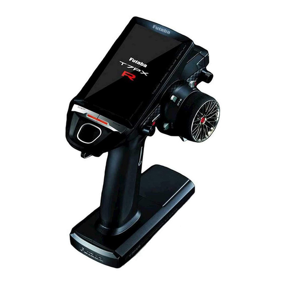
Transmitter T7PXR Nomenclature Touch screen LCD Power switch Digital Trim 2 (DT2) Display switch (default throttle trim) Digital Trim1 (DT1) (default steering trim) Digital Dial (DL1) /Push switch 6 (PS6) Home button Steering wheel Hook Push switch 3 (PS3) Digital Trim4 (DT4) Push switch 2 (PS2) Grip Handle A vibration motor is built into the grip handle... -
Page 16: Battery Replacement Method
There is the danger of collision if the power is cut while running (cruising). The use of Futaba genuine Ni-MH or LiFe batteries is strongly recommended. -
Page 17: When Using The Optional Battery
When Using The Optional Battery chargeable battery. Battery Replacement Method Refer to the previous description and remove the transmitter battery cover. Battery cover After removing the dry cell battery box from the transmitter, disconnect the connector. Caution If you remove the dry cell battery box from the transmit- ter, replace it carefully with the wiring on the same side as before. -
Page 18: When Charging For The Optional Battery
When Charging For The Optional Battery Charging A Ni-MH Battery (Example: When charging Futaba Ni-MH battery with the special charger) Plug the transmitter cord of the special charger into not been used for some time, repeat charging 2 or 3 the charging jack on the rear of the transmitter. -
Page 19: Power & Display Switch
Warning Never plug it into an outlet having other than the indicated voltage. Plugging the charger into the wrong outlet could result in an explosion or fire. Do not insert and remove the charger when your hands are wet. It may cause an electric shock. Always use the special charger or a quick charger for digital proportional R/C sets to charge a digital pro- portional R/C set battery. -
Page 20: Display When Power Switch Is Turned On
Display When Power Switch Is Turned On The current system is displayed. Total timer or clock display (H:M) (T-FHSS SR/T-FHSS/S-FHSS/FASST) Battery voltage display When turned on by DSP switch, "Dis- Telemetry function play" is displayed Receiver -> Transmitter The reception strength is shown. Model #, Model name (15 characters) User name (15 characters) T-FHSS/S-FHSS/FASST - Response type... -
Page 21: Steering Wheel And Throttle Trigger Operation
Steering Wheel And Throttle Trigger Operation (CH1: Steering wheel, CH2: Throttle trigger) Throttle trigger function Steering wheel function Forward Pull Left turn Right turn Push brake or back Left Right Digital Trim Operation (Initial settings: DT1: Steering trim, DT2: Throttle trim, DT3: Channel 3, DT4: Channel 4, DT5: Steering D/R, DT6: ATL-Brake rate) •... -
Page 22: Mechanical Atl Adjustment
Mechanical ATL Adjustment throttle trigger for operation feel. Adjustment Using a 1.5mm hex wrench, adjust the trigger brake (reverse) stroke. (The screw moves the throttle trigger stopper.) • When the screw is turned clockwise, the stroke becomes narrower. Adjust the stroke while watching the screw. Mechanical ATL adjusting screw Note:... -
Page 23: Trigger Slide Adjustment & Remove The High Point Spring
Trigger Slide Adjustment & Remove The High Point Spring Adjustment Using a 2.0mm hex wrench, loosen the trigger slide mounting screw by turning it slightly counterclockwise. Always loosen this screw. Note: range of mark. Adjust the trigger slide position within the marked range. -
Page 24: Changing Wheel Position And Modifying For Left-Hand Use
Changing Wheel Position And Modifying For Left-hand Use Changing the wheel position Modifying for left-hand use stallation direction can be reversed. The angle can be adjusted The angle can be finely adjusted by adjusting the steering wheel unit installation. (See the modification method on the next page for the adjustment details.) The operating angle of the wheel can be adjusted The operating angle of the wheel can be changed from 34 deg to 32 deg by installing the... -
Page 25: Installing The Accessory Apa Steering Wheel Offset Adapter
Installing the accessory APA steering wheel offset adapter - Obtain 2.5mm hex wrench./Remove The battery. - The length of the screws used at each part differs. When reassembling the steering wheel unit, always use the specified screws. Remove the two screws (3.0 x12 mm cap screws) for steering wheel unit mounting. - Page 26 Pass the wiring from the steering wheel unit through the hole in the APA, as shown in the figure. Using a Phillips screwdriver, fasten the wheel unit and APA at the desired angle us- ing the 2.6x19 tapping screws. - - Be careful that the screw length is correct. Be cautious that the wiring does not get pinched. - The 2.6x19 tapping screws in the accessory bag.
-
Page 27: Modifying For Left-Hand Use
Install the assembled steering wheel unit and APA to the transmitter using the screw (3.0x12mm cap screw) supplied. (Using a 2.5 mm hex wrench.) - Install slowly so that the wiring is not pinched. - Installation is easy if inserted in 1 2 order. Steering wheel unit mounting screws Steering wheel unit... - Page 28 Install the charging unit to the connector on the opposite side of the transmitter body. • Install slowly so that the wiring is not pinched. Charging unit Using a 2.5 mm hex wrench, attach the Charge unit mounting screws charging unit and the transmitter body with mounting screws.
-
Page 29: Using The Optional Angle Spacer
Angle spacer " Angle spacer ". " Angle spacer ". Angle spacer Example of installing angle spacer Angle spacer 2.6x15mm 2.6x10mm tapping screws tapping screws 2.6x8mm Mount the angle spacer and wheel unit with tapping screws 2.6x15mm tapping screws. 2.6x10mm tapping screws 2.6x8mm tapping screws... -
Page 30: Non-Telemetry Led (Telemetry Off Sign)
Non-telemetry LED (telemetry OFF sign) telemetry function is not operating. Non-telemetry LED (Lit when telemetry function is OFF) Handling the antenna and card slot and receiver About The Transmitter Antenna Cannot rotate more than Antenna Antenna Antenna Moving Range 90˚.If rotated forcibly, the antenna will be damaged. -
Page 31: Receiver Terminology
Receiver Terminology R334SBS Connectors Coaxial cable Antenna Link switch/LED CH4 servo(CH4) CH3 servo(CH3) Throttle servo(CH2) Steering servo(CH1) S.BUS2 :Power/S.BUS2 connector R334SBS-E Connectors Link switch/LED CH4 servo(CH4) CH3 servo(CH3) Throttle servo(CH2) Steering servo(CH1) Antenna S.BUS2 :Power/S.BUS2 connector The receiver power supply can be connected to the S.BUS2 connector or each of CH1-4. Receiver Installation NOTE: The operating range may be reduced, depending on where the receiver and the antenna are mounted. -
Page 32: Handling A Microsd Card (Commercial Product)
Under other conditions, the set will not operate, or the specified performance will not be displayed even if it operates. In ad- dition, it may cause trouble with servos and other equipment. Futaba will not be responsible for damage, etc. caused by combination with the products of other companies. -
Page 33: Installation
Installation Receiver And Servo Connections " Installation Safety Precautions " on the next page. the motor and battery depends on the motor controller used. Purchase the motor controller and servos separately. The receiver also depends on the set. Installation When An Electronic Speed Control Is Used Installation For Gas Powered Models CH4 servo CH3 servo... -
Page 34: Installation Safety Precautions
Connection example of S. BUS using a telemetry sensor Switch Telemetry sensors Receiver (Option) Temperature sensor RPM sensor S.BUS2 S.BUS2 Each telemetry sensor is connected Voltage sensor to the S.BUS 2 port collectively with a hub or double extention cable. Note: In SR mode, the S.BUS 2 port cannot be used other than battery input. - Page 35 Warning Receiver Vibration-proofing/Waterproofing (Car) Vibration-proof the receiver by wrapping it in foam rubber or other vibration-absorbing material and mount it with thick double-sided tape. When using the receiver holder supplied with the model kit, mount the holder to the chassis through a rubber grommet.
- Page 36 Warning Servo Throw Operate each servo over its full stroke and be sure the linkage does not bind or come loose. The continuous application of unreasonable force to a servo may cause damage and excessive battery drain. Caution! A whining noise indicates that the steering servo is improperly set.
-
Page 37: Initial Set-Up
"T-FHSS SR" is displayed output typically, " T-FHSS SR " , " T-FHSS " , " S-FHSS " , or " FASST " is so contact a Futaba Service Center. " DSP " side, " Display " is displayed. the T7PXR receiver setup must set to T-FHSS SR or T-FHSS. -
Page 38: Receiver System Change & How To Link
Receiver system Change & How To Link First, set up the " Receiver " function. Setting changes are immediately ref lected. Next, the transmitter and receiver are linked, and the receiver memorizes the trans- The method of setting up the receiver system and the method of linking the transmitter and Set the transmitter "PWR"... - Page 39 After setting up this far is complete, when using a FASST system (R614FS/FF/FF-E) or S- FHSS system (R2104GF, R204GF-E, etc.) receiver, go to "S-FHSS/FASST Receiver Link" on page 40. When using a T-FHSS SR receiver (R334SBS) and T-FHSS receiver (R304SB, etc.), go to the next step 3.
-
Page 40: S-Fhss/Fasst Receiver Link
Precaution: If there are many Futaba 2.4GHz systems turned on close to your receiver might not link to your transmitter. In this case, even if the receiver’s LED stays solid green, unfortunately, the receiver might have established a link to one of the other transmitters. -
Page 41: Kyosho Mini-Z Evo Dedicated Receiver Ra-42
Kyosho Mini-Z EVO dedicated receiver RA-42 Display the "Receiver setting" screen from the "Linkage menu" or "User menu". Set the system to "Mini-Z T-FHSS". Bring the transmitter and the receiver close to each other, within 20-inches (half a meter). Turn on the Mini-Z receiver RA-42. -
Page 42: Response Mode/Sr Check
Response Mode/SR Check Make sure that the response mode or SR mode setting matches the servo or other equipment to be used. Response mode is displayed. Display ON/OFF of SR mode. "Digital servo" In the case of the channel indicated as [SR], SR mode is ON. - Page 43 Under other conditions, the set will not operate, or the specified performance will not be displayed even if it operates. In addition, it may cause servo trouble. Futaba will not be responsible for problems caused by the use of other than Futaba genuine parts. Use...
-
Page 44: Trigger Ratio Check
Throttle Ratio Check -The throttle brake operation might be close by setting it to " " Forward 50: Brake 50 Forward 70: Brake 30 Forward 100: Brake 0 Forward 70: Brake 30 Forward 100: Brake 0 Forward 50: Brake 50 Throttle mode Trims Initial Set-Up - Steering trim (DT1) check... - Page 45 - Steering dual rate (DT5) check - Brake rate (DT6) check Steering dual rate DT5 Brake rate (Brake1) DT6 Steering dual rate Brake rate (Set-Up Procedure When Installed In a Car) recommended. Initialize all the trims to zero/dual rate and brake rate to 100. Set the servo direction of operation using the Reverse function.
-
Page 46: Function Map
Function Map Menu Selection Display Menu Screen or tap the touch panel. button. Tap [User Menu] on the home screen to display the "User menu" screen. (User menu screen) Tap the [Menu] on the home screen or press the HOME button to display the menu screen. -
Page 47: Home Button Setting
Home Button Setting on the menu screen or each setting screen to return to the Home screen. The setting screen - Push------------------Display menu screen or custom menu screen. " Home button setting " of " Accessory menu " (Menu screen) (Accessory menu screen) (Home button setting screen) Select a screen to display by... -
Page 48: Value Of Each Function And Changing The Set Value
Value Of Each Function And Changing The Set Value Example: To change the right-hand side steering amount on the End point screen, tap the right of the steering wheel, and when [-] [reset] [+] is displayed at the bottom of the screen, press + To decrease, tap [-] to change the numerical value. -
Page 49: User Menu
User Menu Displaying And Editing The User Menu Screen " Home button setting " function. Menu assignment Tap the [Edit] on the user menu screen. A confirmation screen will appear with "User menu setting Are you sure?" to edit, tap [Yes] to display the edit screen. If you don’t want to edit it, please tap [No]. -
Page 50: Function List
Function List Function Name Description Of Function Page Backlight brightness setting/dimming time setting/touch panel correction Display Information Sound Battery Date and time setting/Displaying the time on the home screen or selecting the total timer Date And Time LED Setting Calibration Software Update Receiver Update Model memory call... - Page 51 Pulse brake A.B.S Throttle preset at start function Start Engine Cut Steering Mixing Brake Mixing The sensitivity of Futaba car rate gyros can be adjusted Gyro Mixing 4WS Mixing Front and rear ESCs mixing Dual ESC CPS Mixing For Tank mixing...
-
Page 52: Function Map
Function map Receiver Servo view Throttle mode (Trigger) Channel Reverse 37/54 Home screen Linkage menu-1 Sub trim End point Fail-safe Acceleration Menu screen Trim/Dial select Switch select Condition Idle-up Linkage menu-2 D/R,ATL Channel limiter Channel setting Model select Model copy Model name Model delete Data reset... - Page 53 Function map Curve(EXP) Speed Traction control A.B.S Start Engine cut Racing menu Home screen Mixing menu-1 Steering mixing Brake mixing Gyro mixing 4WS mixing Dual ESC Menu screen CPS mixing Tank mixing Program. mixing Mixing menu-2 Tilt mixing Receiver Update System menu-1 Accessory menu System menu-2...
-
Page 54: Functions
Function Receiver This menu selects the settings matched to the receiver system used and the type of servo T-FHSS telemetry system receiver is described on pages 37 to 41. Linkage menu Receiver Menu screen Home screen Menu-1 Menu-2 Telemetry function ON/OFF (Function ON/OFF) Setting Tap telemetry (ON) or (OFF) to select ON/... -
Page 55: Channel Reverse
Channel Reverse This function reverses the direction of operation of the servos related to transmitter steering, throttle, channel 3, channel 4, and auxiliary channels operation. the center, the center becomes the opposite side. Linkage menu Channel Reverse Menu screen Home screen Menu-1 Menu-2 Tap to change page. -
Page 56: Sub Trim
Sub Trim teering, throttle, channel 3, chan- nel 4, and auxiliary channels servos. Linkage menu Sub trim Menu screen Home screen Menu-1 Menu-2 Tap to change page. For the S-FHSS (analog) system, channels 5, 6, and 7 are displayed *Sub trim adjusts the entire range of on the 2nd page. -
Page 57: End Point
End Point side/brake side manipulated variable, change the channel 3, channel 4, auxiliary channel Maximum steering angle The End point function determines the maximum steering angle of each channel. are adjusted. ---------------------------------------------- ---------------------page 126 ---------------------------------------------------- page 74 --------------------------------------------- ----------------------------------- page 62 Brake rate trim rate trim must also be taken into account. - Page 58 Linkage menu End point Menu screen Home screen Menu-1 Menu-2 Tap to change page. Steering end point adjustment (Preparation) - Before setup of the steering end point adjustment, set the steer- ing D/R dial (initial setup: DT5) to the maximum steering angle position 100%.
- Page 59 Throttle end point adjustment (Preparation) Adjustment buttons - Use the [+] and [-] buttons to - Before setting the throttle end point adjustment, set the throttle make adjustments. ATL dial (initial setup: DT6) to the maximum throttle angle po- - Return to the initial value by tapping the [reset] buttons.
-
Page 60: Fail-Safe/Battery Fail-Safe
Fail-safe/Battery Fail-safe by the receiver for some reason, or the battery voltage has dropped. -Fail-safe mode signals from the transmitter for some reason. * Note after the receiver is turned on. Hold mode This function stops the output of signals to the servos and places the servos into the free ter can be received again recovers, the battery fail-safe function is automatically reset. - Page 61 Fail-safe mode selection (Preparation) - Tap the fail-safe part of the channel you want to set. The mode list appears on the Fail-safe menu screen. (Mode selection) Tap from the list and select the mode. To cancel, tap [Cancel]. Fail-safe mode Off, Hold, Fail-safe (Each channel can be individually set.) When finished with Hold mode or Off mode setting, return to the Linkage menu screen by press-...
-
Page 62: Acceleration
Acceleration " jumps " Operation 100% tle trigger neutral position 100% becomes a sharp rise. sides can be set separate- Forward Brake set, the auxiliary channel brake can also be set. Set value throttle end point function. Convenient usage method For gasoline engine cars, the linkage must have Clearance clearance because one servo controls the engine... - Page 63 Throttle acceleration adjustment Adjustment buttons (Preparation) Adjust with the [+] and [-] but- - Tap the value button of the [Forward]. Value input buttons appear tons. - Return to the initial value by on the screen and make the following adjustments: tapping the [reset] buttons.
-
Page 64: Throttle Mode (Trigger)
Throttle mode (Trigger) -Servo neutral mode: -Neutral brake: To use the " Neutral brake " " " necessary. Linkage menu Throttle mode (Trigger) Menu screen Home screen Menu-1 Menu-2 Throttle servo neutral position "Ratio" Forward 70: Brake 30 Forward 100: Brake 0 Forward 50: Brake 50 Selecting the trigger ratio (Throttle mode selection) - Page 65 Neutral brake "Rate" Neutral Brake function adjustment (Preparation) - Use the switch select function to the "Switch select". (page 71) When the switch is not set, "A switch is not assigned" is dis- played. Tap [Switch select] to display the switch selection screen and set the switch.
-
Page 66: Servo View
Servo View The servo operation of each channel can be checked. Process of the steering angle adjust- Linkage menu Servo view Menu screen Home screen Menu-1 Menu-2 For the S-FHSS (analog) system, channels 5, 6, and 7 are displayed on the 2nd page. Confirm operation Operating each channel, such as a steering wheel or throttle trigger, the graph moves, and the servo operation can be confirmed. -
Page 67: D/R, Atl
D/R, ATL The steering left and right servo travels are adjusted simultaneously. This setting is linked Linkage menu D/R, ATL Menu screen Home screen Menu-1 Menu-2 Dual rate adjustment Tap the travel button of the [Dual rate]. Val- Adjust button ue input buttons appear on the screen and Adjust with the [+] and [-] but- tons. -
Page 68: Trim/Dial Select
Trim/Dial Select Linkage menu Trim/Dial select Menu screen Home screen Menu-1 Menu-2 The screen display Example: The trim/dial is assigned to the gyro mixing function. Function select dial setup Tap the trim or dial you want to set. (DT1, 2, 3, 4, 5, 6/DL1) The value of the gyro gain is indicated to the top of the The function list appears on the Trim/Dial select menu... - Page 69 Setting direction (Changing the operation direction) - Tap [Nor.]/[Rev.]. Tap [Nor.] or [Rev.] in the direction to set the (Nor.) Normal/(Rev.) Reverse direction. (Changing the operation step amount) Adjust button Tap the travel button of the [step]. Value in- Adjust with the [+] and [-] but- tons.
- Page 70 Set table functions (DL1/DT1, DT2, DT3, DT4, DT5, DT6) Abbreviation used on the Abbreviation displayed Function name, etc setup screen on the opening screen Steering trim Steering trim Steering trim Throttle trim Throttle trim Throttle trim Channel 3 to 7 control Channel 3 to 7 control Channel 3 to 7 control (Channel 5 to 7 is for S-FHSS analog system only.) Flap...
-
Page 71: Switch Select
Switch Select operation. Linkage menu Switch select Menu screen Home screen Menu-1 Menu-2 The steering switch and trig- ger switch are displayed on the 2nd page. Function select dial setup Function list (Function setup) See page 73 Tap the switch you want to set. (PS1, PS2, PS3, PS4, PS5, PS6/steer ing wheel, throttle trigger) Since there are... - Page 72 Setting direction (Changing the operation direction) - Tap [Nor.]/[Rev.]. Tap [Nor.] or [Rev.] to set the direction. (Nor.) Normal/(Rev.) Reverse (Changing the type of operation) Tap [Nor.] or [Alt.] to set the type. Setting type - Tap [Nor.]/[Alt.]. (Nor.) Normal/(Alt.) Alternate Adjust button (Steering/trigger switch setting) Adjust with the [+] and [-] but-...
- Page 73 Set table functions (PS1/PS2/PS3/PS4/PS5/PS6) & steering switch (SS) Trigger switch (TS) Abbreviation used on the setup screen Function name, etc Channel 3 to 7 control Operation of channel 3 to 7 (Channel 5 to 7 is for S-FHSS analog system only.) Condition 1 Change between condition 1 and 2 Condition (1-5)
-
Page 74: Idle-Up
Idle-Up To use the " " " " necessary. This function is used to improve engine starting performance by raising the that the ESC is in the neutral position and the set is in the operation mode before setting the Operation age locking, etc. - Page 75 Idle-up function adjustment (Preparation) - Use the switch setting function to the "Switch select". (page 71) When the switch is not set, "A switch is not assigned" is displayed. Tap [Switch select] to display the switch selection screen and set the switch.
-
Page 76: Channel Limiter
Channel Limiter The channel limiter function limits the maximum servo movement. By superimposing mix- ing, the linkage can be protected by setting the limiter in case servo motion becomes unex- pectedly large. Linkage menu Channel limiter Menu screen Home screen Menu-1 Menu-2 Tap to change page. -
Page 77: Channel Setting
Channel Setting This function assigns steering or throttle to any channel. You can operate steering and throt- Linkage menu Channel setting Menu screen Home screen Menu-1 Menu-2 How to select steering/throttle (Channel setup) Tap the channel you want to set, and the [Steering], [Throttle] setting screen will be displayed. -
Page 78: Condition
Condition " Condition " can be set for each model. - To use the " Condition " " func- " " Trim/Dial select " - It is possible to name the condition. - First, the initial settings of each condition 2 to 4 functions are created. function is indicated by an audible alarm, and the condition number is displayed in the up- -The functions that can be set at each condition are displayed by condition number at the top of the menu screen. - Page 79 Tap the [Condition] button to change the number of available conditions. A list of condition numbers is displayed in the "Condition name" group box. Up to 4 condi- tions can be used. Condition name This function allows you to assign a fifteen character name to each condition. From the "Condition Name"...
- Page 80 Tap the [Copy], The confirmation message "Are you sure" appears. To execute the copy, tap [Yes] and to cancel copy, select [No]. When the copy destination condition name becomes the same name as the copy source, copying is complete. Condition change switch setting This function sets the switch to change the condition.
- Page 81 Condition change trim/dial setting This function can change the condition by trim or dial. By operating Trim or Dial, you can change the condition as Condition 1 4 or 4 Tap the [Trim/Dial select] button to display the "Trim/Dial select" screen. (The "Trim/Dial se- lect"...
-
Page 82: Curve (Exp)
Curve (EXP) Steering curve This function is used to change the sensitivity of the steering servo around the neutral posi- " Fine-tune " can adjust the rate for left and right separately. Steering curve Menu screen Racing menu screen Curve screen Home screen Quick Mild... - Page 83 Steering EXP adjustment Adjustment buttons (Preparation) - Adjust with the [+] and [-] but- -Tap the curve type and select [EXP]. tons. - Return to the initial value by Tap the value button of the [EXP rate]. tapping the [reset] buttons. Value input buttons appear on the screen.
-
Page 84: Throttle Curve (Forward Side)
Throttle curve (Forward side) This function makes the throttle high side direction servo operation quicker or milder. It has Advice Throttle curve Menu screen Racing menu screen Curve screen Home screen * Tap the type to switch the curve type. EXP curve screen VTR curve screen Curve screen... - Page 85 Adjustment method for EXP curve (Preparation) Adjustment buttons -Tap the curve type and select [EXP]. - Adjust with the [+] and [-] but- tons. - Return to the initial value by Tap the value button of the [EXP rate]. tapping the [reset] buttons. Value input buttons appear on the screen.
- Page 86 Adjustment buttons Adjustment method for Curve - Adjust with the [+] and [-] but- (Preparation) tons. - Return to the initial value by -Tap the curve type and select [Curve]. tapping the [reset] buttons. Curve rate Tap the value button of the [Point rate] (1 +0~+100 to 9).
-
Page 87: Brake Curve
Brake curve This function makes the servo operation on the brake side faster or gentler. It does not af- fect the maximum servo movement. The selection from among three kinds of curves (EXP/ Brake curve Menu screen Racing menu screen Curve screen Home screen When brake mixing (page 110) -
Page 88: Speed
Speed Steering speed This function is useful in such cases. Understeering Spin Smooth cornering Without "Steering speed function" With "Steering speed function" Operation dently set. the set speed, the steering servo is not af- fected. Steering speed Menu screen Racing menu screen Speed screen Home screen Speed... - Page 89 Adjustment buttons Steering Speed adjustment - Adjust with the [+] and [-] but- tons. ("Turn" direction delay adjustment) - Return to the initial value by Tap the value button of the [Turn]. Value input buttons appear tapping the [reset] buttons. on the screen.
-
Page 90: Throttle Speed
Throttle speed Without "Throttle speed function" With "Throttle speed" function Quick start without skidding Slow start due to skidding Operation the throttle trigger is operated more than necessary. This delay function is not performed - " 1 " speed, " 2 " speed, or " 3 " speed can be selected. Throttle speed Menu screen Racing menu screen... - Page 91 Adjustment buttons Adjustment method for 1 Speed mode - Adjust with the [+] and [-] but- (Preparation) tons. - Return to the initial value by -Tap the speed mode and select [1]. tapping the [reset] buttons. ("ALL" turn direction delay adjustment) Speed range 1~100 Tap the [Turn] side of the [All] value button.
- Page 92 Adjustment buttons ("Low" and "High" return direction delay adjustment) - Adjust with the [+] and [-] but- tons. Tap the [Return] side of [Low] or [High] - Return to the initial value by value button. A warning is displayed tapping the [reset] buttons. saying "Return speed will be slow.
- Page 93 Adjustment buttons ("Low", Middle", and "High" return direction delay adjustment) - Adjust with the [+] and [-] but- tons. Tap the [Return] side of [Low], [Middle] - Return to the initial value by or [High] value button. A warning is tapping the [reset] buttons.
-
Page 94: Pulse Brake
A.B.S other types of vehicles, understeer may occur. The tendency to under- steer can be eliminated and corners can be smoothly cleared by using this function. Operation Without "A.B.S" full-size car - The brake return amount, pulse cycle, and brake duty can be ad- justed. - Page 95 - Delay proximately 1.4-seconds. - Cycle speed - Duty ratio Sets the proportion of the time the brakes are applied, and the time the brakes are released - Trigger point When the trigger ratio was set to 100:0 does not operate even if the ABS function is set. A.B.S.
- Page 96 Adjustment buttons ("Delay" amount setup) - Adjust with the [+] and [-] but- tons. Tap the value button of the [Delay]. Value - Return to the initial value by input buttons appear on the screen. Use tapping the [reset] buttons. the [+] and [-] buttons to adjust the delay amount.
- Page 97 Adjustment buttons ("Trigger point" setup) - Adjust with the [+] and [-] but- tons. Tap the value button of the [Trigger point]. Value input buttons - Return to the initial value by appear on the screen. Use the [+] and [-] buttons to adjust tapping the [reset] buttons.
- Page 98 Switch setting Trim/Dial Setting Example of A.B.S. function setting when S9373SV used Delay: Reduce the delay. applied fully. A.B.S...
-
Page 99: Traction Control
Traction control smooth cornering cannot be done. By intermittently operating the operation of the throttle, mittently operating the motor in the high point direction, a pseudo revving engine sound can be reproduced. Operation direction. pumping, the operating point, and the duty ratio of pumping. point side. - Page 100 - Delay - Cycle speed - Duty ratio in the pumping operation. - Trigger point Traction control function adjustment (Function ON/OFF) Tap "Mixing" (ON) or (OFF) to select ON/ OFF. "OFF": Traction control function OFF "ON": Traction control function ON * Displays ON/OFF of the condi- tion that traction control is work- When using traction control function ON/...
- Page 101 Adjustment buttons ("Delay" amount setup) - Adjust with the [+] and [-] but- tons. Tap the value button of the [Delay]. Value - Return to the initial value by input buttons appear on the screen. Use tapping the [reset] buttons. the [+] and [-] buttons to adjust the delay amount.
- Page 102 Adjustment buttons ("Trigger point" setup) - Adjust with the [+] and [-] but- tons. Tap the value button of the [Trigger point]. Value input buttons - Return to the initial value by appear on the screen. Use the [+] and [-] buttons to adjust tapping the [reset] buttons.
-
Page 103: Start
Start If the track is slippery and you begin to accelerate by pushing the trigger to full throttle, the grip and the car accelerates smoothly. Without the "Start" function With the "Start" function Tires grip the track firmly- Car accelerates Wheels spin- Car does not accelerate Operation servo moves to the preset position. - Page 104 Adjustment buttons ("Trigger point" setup) - Adjust with the [+] and [-] but- Tap the value button of the [Trigger point]. tons. - Return to the initial value by Value input buttons appear on the screen. tapping the [reset] buttons. Use the [+] and [-] buttons to adjust the op- eration point.
-
Page 105: Engine Cut
Engine cut Menu screen Racing menu screen Engine cut Home screen Engine cut ON/OFF is indicated on the home screen for a few seconds. heard. Immediately set I t i s d i s p l ay e d i n t h e h o m e screen, when the engine cut is Warning display When the trigger ratio was set to 100:0... - Page 106 (Preset position setup) *Shows the ON/OFF state Tap the value button of the [Preset]. Value Adjust button input buttons appear on the screen. Use the Adjust with the [+] and [-] but- [+] and [-] buttons to set the preset position tons.
-
Page 107: Steering Mixing
Steering Mixing and right steering can be set independently, so smooth cornering is possible. By using the " Steering mixing rate " function, the motions of the servos on the left and right sides of the steering can be adjusted at the same time. The right side steering servo or the left side steer- ing servo connects to receiver channel 1, and the other side connects to receiver auxiliary left and right servos are adjusted individually, Ackerman can also be adjusted by the Ack- erman rate. - Page 108 (Channel setup) The channel list screen used for steering 2 is displayed. Tap the auxiliary channel that con- nected the servo of steering 2. - When all channels are in use, a screen saying "No assignable channel" is displayed, please turn off other mixing and select an unused channel.
- Page 109 (Steering mixing rate adjustment) Adjustment buttons Tap the value button of the "Steering mixing - Adjust with the [+] and [-] but- rate" [Left] or [Right]. Value input buttons tons. - Return to the initial value by appear on the screen, adjust each of the tapping the [reset] buttons.
-
Page 110: Brake Mixing
Brake Mixing vos, or controls the 2nd channel by the independent throttle and controls the rear and front rate in proportion to steering operation is possible. Operation -Brake 2 and brake 3 amount, brake 1,2,3 delay, and Brake 2 and brake 3 EXP and ABS can be set. - Page 111 Mixing menu Brake mixing Menu screen Home screen Menu-1 Menu-2 Brake mixing ON Brake mixing Brake mixing Brake mixing Brake 2 "ON" Brake 3 "ON" Brake 2&3 "ON" The mixing function is assigned to auxiliary channels used by another mixing cannot be Steering mixing adjustment Setting (Function ON/OFF)
- Page 112 (Channel setup) The channel list screen used for brake 2 or brake 3 is displayed. Tap the auxiliary channel that connected the servo of brake 2 or brake 3. - When all channels are in use, a screen saying "No assignable channel" is displayed, please turn off other mixing and make an unused channel.
- Page 113 (Steering mixing) Use this function when you want to soften Adjustment buttons the brakes when the steering is operated. - Adjust with the [+] and [-] but- Tap the value button of the "Brake 1 or 2,3" tons. - Return to the initial value by [Left].
-
Page 114: Gyro Mixing
Gyro Mixing gyro at the T7PXR side, and is mixing that uses the auxiliary channels to improve the gyro For a description of the " Car rate gyro " mounting method and handling, refer to the rate gyro instruction manual. not operate properly. - Page 115 Gyro mixing adjustment (Preparation) - Refer to the gyro instruction manual and connect the gyro to the receiver. When using remote gain, connect gyro sensitivity adjustment to the auxiliary channels of the receiver. - When using gyro mixing by switching between the NORM (normal) and AVCS modes, use the switch select function (page 71) to set the switch to be used.
- Page 116 Setting (Gyro mixing type selection) - Tap Gain type. 1 gain/2 gain/4 gain Tap the Gyro type and select [1 gain], [2 gain] or [4 gain]. "1 gain" :One mode only "2 gain" :Switching Gyro gain 1 and Gyro gain 2 "4 gain"...
-
Page 117: 4Ws Mixing
4WS Mixing the 1st channel to control front side steering and the auxiliary channel to control rear side steering. " " Mixing menu 4WS mixing Menu screen Home screen Menu-1 Menu-2 When the mode is activated by a switch, indicated on the home screen for a few seconds. - Page 118 (Channel setup) The channel list screen used for rear steering is displayed. Tap the auxiliary channel that connected the servo of rear steering. - When all channels are in use, a screen saying "No assignable channel" is displayed, please turn off other mixing and make an unused channel.
- Page 119 Adjustment buttons (Rear side travel adjustment) - Adjust with the [+] and [-] but- Tap the value button of the [Rear mix rate]. tons. - Return to the initial value by Value input buttons appear on the screen, tapping the [reset] buttons. use the [+] and [-] buttons to adjust the rear side travel amount.
-
Page 120: Dual Esc
Dual ESC uses the 2nd channel to control the rear motor controller and the auxiliary channel to control the front motor controller. Mixing menu Dual ESC Menu screen Home screen Menu-1 Menu-2 The mixing function is assigned to auxiliary channels used by another mixing cannot be Display the current drive mode. - Page 121 (Channel setup) The channel list screen used for the front ESC channel is displayed. Tap the auxiliary chan- nel that connected the front ESC channel. - When all channels are in use, a screen saying "No assignable channel" is displayed, please turn off other mixing and make an unused channel.
-
Page 122: Cps Mixing
CPS Mixing (1, 2, 3 ) the " CPS mixing " brake side operation. Three lines of CPS mixing can be used. nect it to the channel of the normal mode. Mixing menu CPS mixing Menu screen Home screen Menu-1 Menu-2 The mixing function is assigned to auxiliary CPS function ON/OFF... - Page 123 (Channel setup) The channel list screen used for the CPS channel is displayed. Tap the auxiliary channel that connected the CPS-1 unit channel. - When all channels are in use, a screen saying "No assignable channel" is displayed, please turn off other mixing and make an unused channel.
-
Page 124: Tank Mixing
Tank Mixing This function is intended for vehicles such as tanks and can be used for the pivotal turn, or the ultra-pivotal brake turn, by steering and throttle operation. Tank mixing Menu screen Home screen Menu-1 Menu-2 Connection channel The channels connecting the left and right motor control- lers are as shown in the figure. - Page 125 (Limit ON/OFF) Setting - Tap (ON)/(OFF). It is a function to limit the maximum opera- tion amount of the steering and throttle channel so that it does not exceed the limit by the influence of the mixing amount. Tap "Limit" (ON) or (OFF) to select ON/OFF. "OFF": Limit function OFF "ON": Limit function ON...
-
Page 126: Program Mixing (1, 2, 3, 4, 5 )
Program Mixing (1, 2, 3, 4, 5 ) channel. Additional Functions Movement of the slave channel side side. When the trigger ratio was set to 100:0 channel is set to throttle, mixing operates only at the " " side. It does not operate at the "... - Page 127 Program composite adjustment (Preparation) Setting - Use the switch select function (page 71) to select the switch. - Tap (ON)/(OFF). (as desired) - From the Program mixing screen Tap [Program mixing 1] - [Program mixing 5] to use to move to the setting screen. (Function ON/OFF) Tap [1/2] at the upper right of the screen to display page 2.
- Page 128 (Left, Forward or A side mixing amount adjustment) Adjustment buttons Tap the value button of the "Rate" [Left], - Adjust with the [+] and [-] but- [Forward] or [Rate A]. Value input buttons tons. appear on the screen. Use the [+] and [-] - Return to the initial value by tapping the [reset] buttons.
-
Page 129: Tilt Mixing
Tilt Mixing Tilt mixing uses an outboard engine and applies bidirectional mixing from the rudder to Effect of the set value of other functions on tilt mixing Steering end point function, curve function, speed function, or D/R function setup also Tilt mixing Menu screen Home screen... - Page 130 (Channel setup) The channel list screen used for the gain steering channel is displayed. Tap the auxiliary channel that connected the gain steering channel. - When all channels are in use, a screen saying "No assignable channel" is displayed, please turn off other mixing and make an unused channel.
-
Page 131: Timer
Timer lap navigate timer. Up timer function - An alarm sound can be set. The passage of time is announced by the - Alarm: Generates a beep at the set time (minutes). - Pre-alarm: Alarm advance announcement sound. Sounding begins 10-seconds before the set alarm time. Fuel down timer function - An audible alarm can be set. - Page 132 Lap timer function alarm has elapsed automatically stops the timer. Pre-alarm can also be set. The passage of time is announced by the sounding of a buzzer -Alarm: Generates a beep at the set time. Pre-alarm: Starts sounding the set time (second) before the alarm. (beeps) displayed on the setup screen.
- Page 133 Menu screen Accessory menu screen Timer Home screen Timer selection First, select the type of timer at the "Mode" item. The setup screen varies depending on the type of timer. This figure shows the Up timer setup screen. Time display -Up timer Minute display (min) -Fuel down timer...
- Page 134 Using the Up timer (Preparation) Select the "Up timer" from the timer type list and tap. (Alarm time setting) Alarm time OFF, 1~99-minutes Tap the value button of the "Alarm time". Initial value: 5-minutes Value input buttons appear on the screen. - Adjust with the [+] and [-] but- Use the [+] and [-] buttons to set the time tons.
- Page 135 Using the fuel down timer (Preparation) Select the "Fuel down timer" from the timer type list and tap. (Alarm time setting) Alarm time OFF, 1~99-minutes Tap the value button of the "Alarm time". Initial value: 5-minutes Value input buttons appear on the screen. - Adjust with the [+] and [-] but- Use the [+] and [-] buttons to set the time tons.
- Page 136 Using the lap timer (Preparation) Select the "Lap timer" from the timer type list and tap. Alarm time OFF, 1~99-minutes (Alarm time setting) Initial value: 5-minutes - Adjust with the [+] and [-] but- Tap the value button of the "Alarm time". tons.
- Page 137 Using the lap navigate timer (Preparation) Select the "Lap navigate timer" from the timer type list and tap. Alarm time (Alarm time setting) OFF, 1~99-minutes Initial value: 5-minutes Tap the value button of the "Alarm time". - Adjust with the [+] and [-] but- Value input buttons appear on the screen.
-
Page 138: Lap List
Lap list tion. -The total time and average time are displayed. The faster time is displayed in red charac- ters. -If the lap timer is reset, the lap list is also cleared. Menu screen Accessory menu screen Lap list Home screen Using the lap memory (Lap memory check) The lap time list displays 40 laps per page and 80 laps maximum on two pages. -
Page 139: S.bus Servo
S.BUS Servo " Notes " WARNING In the wireless setting, there is a danger that a car (boat) can become unexpectedly uncontrollable, because the servo temporarily stops working during communication. For safety, in case of electric car (boat), please set with driving wheel (boat propeller) not touching the road surface (water surface). Also, in the case of an internal combustion engine car (boat), be sure to stop the engine before entering wireless set-up mode. - Page 140 Connection between wired transmitter and servo Connecting S.BUS/S.BUS2 servo connector to the trans- mitter Communication port. Communication port. Cover The connection between the wireless receiver and servo Wireless 2 (Rx Ch2) - Reference When using "S.BUS/S.BUS2" servo with steering mixing (Instruction Wireless 1 (Rx Ch1) manual page 107) with a twin servo specification car such as 1/5 GP...
- Page 141 - Communication port: 7PXR communication port (conventional wired setting). - Wireless 1 (Rx Ch1): Receiver channel 1 - Wireless 2 (Rx Ch2): Receiver channel 2 -"Reading succeeded"...
- Page 142 Display data list The type and data of the loaded servo are displayed. Since there are two setting items, change the page as follows. When the connected servo type is not compatible with t h e S R m o d e , " U n s u p - por ted Nor mal mode"...
- Page 143 S.BUS function setup On the setting screen of each function, if you tap the item to be set, "[-] [Reset] [+]" is dis- played at the bottom of the screen, tap the [-] [+] on the panel set. Tap[Reset] to return to the initial value.
- Page 144 This is used when stopping hunting, etc., but the holding characteristic changes as shown below. [Relationship between stretcher and servo operation] Small - Servo holding force becomes weaker. Large - Servo holding force becomes stronger. (Note) When this parameter is large, the current consumption increases. Boost/Boost (ON/OFF) INH: Boost is ON at the time of low-speed operation.
-
Page 145: Mc (Esc) Link
MC (ESC) Link This function is used by connecting ESC directly to the transmitter. mitter and ESC. -Also, connect the battery at the ESC side. Connecting the ESC receiver connector to the transmitter Communication port. Communication port. Cover Battery Menu screen Accessory menu screen Home screen MC (ESC) Link... - Page 146 Using the ESC Link function (Preparation) -Connect the T7PXR and ESC following the connection diagram shown on page 145. -Connect the battery to the ESC. Turn the power on the transmitter. "MC link" menu is displayed referring to the map of page 145.
- Page 147 Display data list Tap the [Data list]. Depending on the ESC type, the setting items are different. If there are multiple pages, move the page as follows. To page 1 MC940/960CR page 1 MC940/960CR page 2 MC940/960CR page 3 MC940/960CR page 4 To page 1 950CR page 1 950CR page 2...
- Page 148 PWM frequency (min) MC401,402CR/601,602C/850,851C :0.1kHz(100Hz) 10kHz (10000Hz) MC950CR :0.5kHz(500Hz) 30kHz(30000Hz) MC940,960CR :1kHz(1000Hz) 30kHz(30000Hz) Same as Link software PWM frequency (at Min. load), MIn sets the " 0" PWM frequency at minimum load. PWM frequency (max) MC401,402CR/601,602C/850,851C:0.1kHz(100Hz) 10kHz (10000Hz) MC950CR:0.5kHz(500Hz) 30kHz(30000Hz) MC940,960CR:1kHz(1000Hz) 30kHz(30000Hz) Same as Link software PWM frequency (at Max.
- Page 149 Low battery protection MC401,402CR/601,602C/850,851C:2.5V 6.0V MC950CR/MC940,960CR 2.5V 7.5V Same as Link software Low Bat Protection. When the power supply voltage drops, the output current to the motor is limited, and the supply voltage to the receiver is ensured. When the power supply voltage drops to the set voltage, a protec- tion circuit operation alarm is activated, and output to the motor is cut.
- Page 150 Brake max. duty All type :0%~100% Same as Link software Brake Max. Duty. This setting can set the braking force between the neutral point and Max brake point. The larger this value, the higher the braking force. When set to "0%", the brakes are not valid. Brake (Reverse) operation Reverse max.
- Page 151 Reverse cancel MC401,402CR/MC950CR/MC940,960CR :ACT/INH Same as Link software Reverse Cancel. When set to "ACT", the reverse operation is not performed. Robot mode MC401,402CR/MC950CR/ MC940,960CR :ACT/INH Same as Link software Robot Mode. When set to "ACT", brake op- eration is not performed, there is only forward and reverse operation.
- Page 152 BEC voltage MC940,960CR/:6.0V/7.4V Same as Link software BEC Volt. The receiver BEC voltage can be selected from 6.0V and 7.4V. Match the voltage to the rating of the servo connected to the same receiver. This BEC voltage cannot output a voltage higher than the input voltage. For instance, if a 6.0V receiver and servo are used with a power supply voltage of 7.4V or more, set the BEC voltage to 6.0V, and when a high voltage receiver and servo are used, set the BEC voltage to 7.4V.
- Page 153 Lead angle use MC940,960CR :ACT/INH Turn on "Lead angle use" Same as Link software Lead Angle Use. This function is effective when Turbo Mode is Turbo1 or Turbo 2 and sets whether or not the lead angle is used. This setting has prior- ity over the Turbo Mode setting.
-
Page 154: Roll Out Chart
Roll Out Chart This function is designed for pan cars. The roll out chart can be calculated from input val- ues for the number of teeth of the spur gear and pinion gear, and the tire diameter, and dis- played as a table. Menu screen Accessory menu screen Roll out chart... -
Page 155: Gear Ratio Chart
Gear Ratio Chart The Gear Ratio Chart can be calculated from input values for the number of teeth of the spur gear and pinion gear and second gear ratio and displayed as a table. Menu screen Accessory menu screen Gear ratio chart Home screen Setup item Pinion... -
Page 156: Home Button Setting
Home Button Setting - Push------------------Display menu screen or custom menu screen. Menu screen Accessory menu screen Home button setting Home screen How to set the Home button Setting (Setting for push) - Tap [Menu]/[User menu]. Tap "Push" [Menu] or [User menu] to select "Menu"/"User menu". -
Page 157: Home Screen Setting
Home Screen Setting This function displays the telemetry meter or image on the home screen. Normal -Instrument panel Meters that display telemetry information and steering and throttle movement meters can -Picture Images can be displayed for each model data on the home screen. The images that can be "... - Page 158 Setting The meter selection method - Tap [Steering]/[Throttle]/[Each sensor]. (Set the type of meter displayed on the home screen) "Steering": Select the [Instrument panel] in the home screen display Display following the operation of the steering wheel. settings. Tap the meter you want to set on the home screen. "Throttle": Next, select the data to be displayed using the following pro- Displayed following the forward...
-
Page 159: Telemetry System
Current sensor (SBS-01C) Measures external power supply voltages up to 70V, capacity and consumption capacity. GPS sensor (SBS-01/02G) Detect the GPS and measure the position and speed of the car body. Compatibility with non-Futaba sensors (Castle TL0). (Refer to the sensor instruction manual for more information.) Telemetry System... -
Page 160: Telemetry
Telemetry This screen displays and sets the various information from the receiver. It is necessary to set telemetry to the ( can be used in the THFSS system, but not in the THFSS-SR mode. An alarm and vibration can be generated depending on the information. Each information screen sets the alarm and the vibration. -
Page 161: Telemetry: Receiver Battery
Telemetry: Receiver Battery Voltage does not have to be installed. The transmitter’s initial status voltage is also displayed. For a this page. Telemetry Current receiver battery voltage The minimum and maximum when powering ON are shown. Alarm/vibrator ON/OFF and type setting (The arrow indicates that an alarm is generated when the power supply voltage drops below the set... -
Page 162: Telemetry: The Drive Battery Voltage
Telemetry: The Drive Battery Voltage * A drive battery sensor must be installed in the model car. Install and connect the sensor following the sensor instruction manual. Telemetry Current drive battery voltage The minimum and maximum when powering ON are shown. Alarm/vibrator ON/OFF and type setting (The arrow indicates that an alarm is generated when the power... -
Page 163: Telemetry: Rpm
Telemetry: RPM speed, it can be announced by an alarm and vibration. * A RPM sensor must be installed in the model car. Install and connect the sensor following the sensor in- struction manual. Current RPM Telemetry The maximum when powering ON are shown. -
Page 164: Telemetry: Temperature
Telemetry: Temperature * A temperature sensor must be installed in the model car. Install and connect the sensor following the sensor instruction manual. Current temperature Telemetry The minimum and maximum the when powering ON are shown. Alarm and vibrator ON/OFF and type setting (The arrow indicates that an alarm is generated when the... -
Page 165: Telemetry: The Drive Battery Electric Current
Telemetry: The Drive Battery Electric Current played. * A drive battery electric current sensor must Current drive battery electric be installed in the model car. Install and current connect the sensor following the sensor T h e mi n imu m a n d m a ximu m instruction manual. - Page 166 Alarm and Vibrator function setup Adjustment buttons (Limit adjustment) - Adjust with the [+] and [-] but- tons. Tap the " Limit] or " Limit]. Value input buttons appear on " [ " [ - Return to the initial value by the screen.
-
Page 167: Telemetry: Gps
Telemetry: GPS the car. * A GPS sensor must be installed in the model car. Install and connect the sensor following the sensor in- struction manual. * When powered up, the SBS-01/02G begins to acquire GPS satellite data. This process can take several minutes. - Page 168 Alarm and Vibrator function setup Adjustment buttons (Limit adjustment) - Adjust with the [+] and [-] but- tons. Tap the " Limit] or " Limit]. Value input buttons appear on " [ " [ - Return to the initial value by the screen.
-
Page 169: Sensor List
Sensor List certain type of sensor is used, this setting is unnecessary, and the sensor can be used by di- What is a slot? " CH " " slots " . There are slots kind of sensor are used, the sensors themselves must allocate unused slots and memo- rize that slot. - Page 170 How to change start slot and set empty slot (Start slot selection) Start slot selection Tap [Slot], the list of sensors that can be - Tap the slot registered in the start slot, will be dis- played. Sensors that cannot be changed are not displayed.
-
Page 171: Sensor
Sensor initial setting one by one, setting here is unnecessary. You can use it by connecting the pur- type, such as temperature sensor for both battery and motor, you need to register that sensor in the transmitter. Menu screen Telemetry menu screen Sensor Home screen Display of sensor list screen (page 169) -
Page 172: Sensor Reload
Sensor Reload mitter. To load the sensor, connect all sensors to be used to the T7PXR communication port, as and all the slots in the sensor list are unregistered. All the sensors to be used a r e c o n n e c t e d t o t h e T7PXR. -
Page 173: Sensor Register
Sensor Register Connecting S.BUS/S.BUS2 ser vo connector to the T7PXR. Communication port. Cover Sensor (The battery is not necessary) How to change start slot and set empty slot (Start slot selection) Tap the [Register]. The confirmation screen will be displayed. To execute, tap [Yes] to hear an electronic sound and finish setting. -
Page 174: Change Slot
Change Slot This procedure changes the slot number of the one registered sensor. Connect the sensor as Sensor slot change (Change) Tap the [Change slot]. The sensor details screen is displayed. Tap the [Read]. The confirma- tion screen will be displayed. To execute, tap [Yes] to hear an electronic sound and finish reading. -
Page 175: Speech Guide Interval And Log Data Interval Setting
Speech guide interval and log data interval setting Setting interval Adjustment buttons (Setting of speech interval) - Adjust with the [+] and [-] but- tons. Tap the value button of the [Speech in- - Return to the initial value by terval]. -
Page 176: Telemetry Meter Display Settings
Telemetry meter display settings Five telemetry meters displayed on the home screen are displayed. You can select the sensor to display and set the range of display data. It can be set for each meter. Home screen Tap meter to set display range etc. -
Page 177: Model Select
Model Select cannot be used by directly calling from the card. Please copy it to the T7PXR main unit Menu screen Model menu screen Model select Home screen Model where green cursor is currently in use Since there are multiple pages, tap the mark and move the page. -
Page 178: Model Copy
Model Copy The contents of model memory can copy to another model memory. You can also save con- tent to a microSD card for backup or to copy to another T7PXR. Menu screen Model menu screen Model copy Home screen Model copying Copy source (Copy source model selection) - Page 179 When finished, return to the Model menu screen by pressing the HOME button. The microSD card storage destination When a microSD card is installed in the T7PXR, a folder called "Futaba" is created, and folders called "LOG" and "MODEL" are created in it. The "MODEL" folder contains the model data.
-
Page 180: Model Name
Model Name Menu screen Model menu screen Model name Home screen Deletion and cancellation of Move cursor characters (Undo) Tap to select characters Selection of alphabet/number/"kana" Setting the model name and user name Name cursor movement (Moving the cursor to the character you want to change.) Use the [ ]/[ ] tap to move the In the model name, tap [ ], [ ] to move the cursor and cursor. -
Page 181: Model Delete (Model Saved On Microsd Card)
Model Delete (Model saved on microSD card) This function deletes model data saved on the microSD card. card slot. Menu screen Model menu screen Model delete Home screen How to delete model data in the microSD card (selection of model data) If the number of models that do not fit on one page memo- rizes, tap [1/2] in the upper right corner to move the page. -
Page 182: Data Reset
Data Reset This function resets the contents of the currently called model memory. do not initialize the calibration function and system function. -Model data This mode is Initializes only the function setting data. The direct menu function is not initialized. -Telemetry Telemetry related setup data is initialized. -
Page 183: Display
Display This function is Backlight brightness, dimming time, etc. setting and touch panel correction menu. There is also a touch panel sensitivity adjustment. System menu screen Display Menu screen Home screen Menu-1 Menu-2 Display setup (Backlight decrease brightness adjustment) Tap the value button of the [Backlight max, brightness] or [Backlight min, brightness]. - Page 184 "ON": Function ON Setting (Setting of start/end screen) - Tap (ON)/(OFF). This turns the “Futaba T7PXR” show or not show when pow- ering the transmitter on or off. Tap on the "Opening demo" (ON ) or ( OFF) and select ON/ OFF.
-
Page 185: Information
Information System menu screen Information Menu screen Home screen Menu-1 Menu-2 Deletion and cancellation of Move cursor characters (Undo) Tap to select characters Selection of alphabet/number/"kana" Setting the user name Name cursor movement (Moving the cursor to the character you want to change.) Use the [ ]/[ ] tap to move the cursor. - Page 186 Language select Language setting Tap to select from the list (Language select) Tap [Language], a list of languages will be displayed on the screen. If you tap the language you want to use from the list, the language display will be changed and you will be taken to the home screen.
-
Page 187: Sound
Sound This function can set the volume of " " , " ", and " Telemetry speech info " . -The volume of the audible alarm sound can be adjusted. System menu screen Sound Menu screen Home screen Menu-1 Menu-2 Volume adjustment Adjust button (Adjusting the key operation volume) -
Page 188: Battery
Battery " or " NiMH " " alarm to system stopping and is very dangerous. " " tery alarm voltage on your responsibility. Futaba is not responsible for the trouble System menu screen Battery Menu screen Home screen Menu-1 Menu-2... -
Page 189: Data And Time
Data And Time This function adjusts the system clock of the T7PXR transmitter. Perform this setting screen can be set. The total time can be reset at this menu. System menu screen Data and time Menu screen Home screen Menu-1 Menu-2 Date and time setting Adjust button... -
Page 190: Led Setting
LED Setting " , " " or " Backlight " . " System menu screen LED Setting Menu screen Home screen Menu-1 Menu-2 LED setting (Setting pilot LED) Tap the [Pilot LED], a list of lighting mode will be displayed on the screen. tap the lighting mode you want to use from the list. -
Page 191: Calibration
HOME button. If the operation cannot usually be ended even when correction is repeated, please contact the Futaba Service Center. When finished, return to the System menu screen by pressing the HOME button. Calibration... - Page 192 HOME button. When operation cannot usually be ended even when correction is repeated, and cannot be ended usually, contact the Futaba Service Center. When finished, return to the System menu screen by pressing the HOME button. Calibration...
-
Page 193: Software Update
Software Update use of a microSD memory card, the other is the use of NFC communication. The use of System menu screen Software update Menu screen Home screen Menu-1 Menu-1 can update. Depending on the model of the device, the update may not start. In The N-Mark is a trademark or registered trademark of NFC Forum, Inc. -
Page 194: Receiver Update
- Download the zip file of the update data from our website or your local distributor’s website. - Extract the zip file on your computer. A folder named "FUTABA" is created. - Insert the micro SD card that contains the "FUTABA" folder into the T7PXR (see page 32 of the manual). - Page 195 Update method Hold down the Link switch first, and turn ON the receiver. Push switch After the LED flashes red once, release the Link switch and (Link switch) then press it again. As you continue holding down the Link switch, the LED starts flashing red and green.
-
Page 196: Reference
Ratings Transmitter T7PXR - Futaba T-FHSS SR/T-FHSS/S-FHSS/FASST-C2 - 4.3 inch backlighted color TFT liquid crystal touch panel. ber of TFT and is manufactured using high-precision technology. Any bright dots that may appear on your display are intrin- sic of the TFT manufacturing technology. - Page 197 SR mode Compatibility Servos 1/10th EP 1/12th 1/10th 1/8th 1/8th 1/5th On-road Drift Nitro Tour- On-road Off-road beginners scale car Touring ing car Off-road S9370SV S9470SV BLS371SV S9570SV S9372SV S9571SV S9670SV S9373SV S3470SV BLS471SV BLS671SV BLS373SV speed B1 speed T1 speed R1 S-U300 BLS571SV...
-
Page 198: Warning Displays
If the battery goes dead while in operation, you will lose control. Power off forgotten alarm message " " Audible alarm: Continuous tone. - If the alarm is not reset, the auto power off function will au- tomatically turn off the power after 5 minutes. MIX Warning " " Audible alarm: Continuous tone. - The alarm stops even if the [OK] is tapped. However, check the function switch. RF Error RF Error " " Audible alarm: Continuous tone. - To stop the alarm, turn off the power. - Turn the power back on. If the alarm is generated again, request repair from the Futaba Service Center. -
Page 199: T7Px(R)/7Xc Screen Protector
System Error " System error " Audible alarm: Continuous tone. Warning When a system error is generated, immediately stop using the sys- tem and request repair from the Futaba Service Center. If you continue to use the system, the transmitter may malfunction and cause loss of control. T7PX(R) / 7XC Screen Protector *Protect the screen from scratches and dirt. *Slightly smaller than the T7PXR screen size, so it attaches easily and Front backing sticks tight. -
Page 200: Optional Parts
Optional Parts Transmitter Battery Part name Telemetry sensors capacity. T7PX(R) / T4PX Large grip (for transmitter) This handle grip is larger than the standard handle grip. Remove and replace the standard handle grip. - Page 201 Carbon handle (for transmitter) Carbon handle Example of installing carbon handle T7PX (R) / T4PX Angle spacer (10 deg) Angle spacer Example of installing angle spacer T7PX (R) / T4PX APA wheel position offset adapter (25 mm) APA wheel position offset adapter Example of installing APA T7PX(R) / T4PX BRAKE LEVER S / SS 18mm or 20mm 15mm 13mm Normal Aluminum brake levers Example of installing Aluminum brake levers...
-
Page 202: Warranty & Repair Service (In U.s.a.)
WARRANTY & REPAIR SERVICE (IN U.S.A.) (Information needed for repair) or contact the Futaba Service Center at the e-mail address, fax or telephone number listed Phone:1-256-461-9399, FAX:1-256-461-1059 E-Mail: contactus@futaba.com your note: • Your Name, Address and Telephone number Futaba Corporation of America 2681 Wall Triana Hwy Huntsville, AL 35824, U.S.A. (Warranty) be made. - Page 203 ©Copyright 2019. No part of this manual may be reproduced in any form without prior permission. The contents of this manual are subject to change without prior notice. While this manual has been carefully written, there may be inadvertent errors or omissions. Please contact our service center if you feel that any corrections or clarifications should be made. ©FUTABA CORPORATION 2019, 12...