Table of Contents
Advertisement
Advertisement
Chapters
Table of Contents

Related Manuals for FUTABA 7C-2.4GHZ


Summary of Contents for FUTABA 7C-2.4GHZ
- Page 1 7C-2.4GHz INSTRUCTION MANUAL for Futaba 7C-2.4GHz 7-channel FASST Radio control system for Airplanes/Helicopters www.futaba-rc.com\faq\7c-faq.html Technical updates and additional programming examples available at: 1M23N13612 Entire Contents © Copyright 2007...
-
Page 2: Table Of Contents
TABLE OF CONTENTS INTRODUCTION ............3 HELICOPTER FUNCTIONS......... 57 Additional Technical Help, Support and Service..3 Table of contents and reference info for helicopters .. 57 Application, Export and Modification ......4 Getting Started with a Basic Helicopter ..... 58 Usage Precaution............ -
Page 3: Introduction
OUTSIDE NORTH AMERICA Please contact your Futaba importer in your region of the world to assist you with any questions, problems or service needs. Please recognize that all information in this manual, and all support availability, is based upon the systems sold in North... -
Page 4: Application, Export And Modification
Prior approval of the appropriate government authorities may be required. If you have purchased this product from an exporter outside your country, and not the authorized Futaba distributor in your country, please contact the seller immediately to determine if such export regulations have been met. -
Page 5: Meaning Of Special Markings
(which does not require periodic replacement) and not a battery, it still should have regular checkups for wear and tear. We recommend sending your system to the Futaba Service Center annually during your non-flying-season for a complete checkup and service. - Page 6 Always pay particular attention to the flying field's rules, as well as the presence and location of spectators, the wind direction, and any obstacles on the field. Be very careful flying in areas near power lines, tall buildings, or communication facilities as there may be radio interference in their vicinity. At the flying field To prevent possible damage to your radio gear, turn the power switches on and off in the proper sequence: 1.
-
Page 7: Introduction To The 7C
A QUICK INTRODUCTION TO THE 7C SYSTEM Note that in the text of this manual, beginning at this point, any time we are using a feature’s specialized name or abbreviation as seen on the screen of the 7C, that name, feature, or abbreviation will be exactly as seen on the radio’s screen, including capitalization, and shown in a DIFFERENT TYPE STYLE for clarity. - Page 8 RECEIVER: R617FS • Futaba’s small and light weight, powerful 2.4GHz FASST R617FS receiver for flight system can control giant-scale models as easily as park flyers. FASST transmitter module, system and receiver compatibility Receiver Transmitter R606FS R617FS/R607FS TM-7 Module — Okay T6EX 2.4G System...
-
Page 9: Contents And Technical Specifications
CONTENTS AND TECHNICAL SPECIFICATIONS (Specifications and ratings are subject to change without notice.) Your 7C-2.4GHz (packaged with a 7-channel FASST receiver) system includes the following components: • R617FS Receiver Servo S3152 ( Standard, digital ) • Servos, S3004, S3152 or S3001, with mounting Control system: Pulse width control, 1.52 ms neutral... -
Page 10: Accessories
¾ the time of a 4-cell pack. • Gyros - a variety of genuine Futaba gyros are available for your aircraft or helicopter needs. See p. 56 for aircraft or p. 73 for helicopter gyro information. -
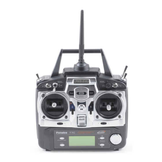
Page 11: Transmitter Controls - Airplane
TRANSMITTER CONTROLS - AIRPLANE SW(F) Snap Roll or Trainer Switch SW(E) Flap Trim Control Landing Gear Carrying Handle Switch Antenna This controls CH6, and if flaperon mixing /CH5 is activated controls the flap. SW(B) Power Rudder Dual Rate Switch LED* /CH7 SW(G) SW(A) - Page 12 TRANSMITTER CONTROLS - HELI Hovering - Pitch Knob SW(H) Power LED* Trainer Switch Antenna SW(B) Rudder Dual Rate Switch Carrying Handle /CH7 SW(G) SW(A) Throttle - Hold Switch Elevator Dual Rate Switch SW(D) /TH-CUT/P-MIX/TIMER Aileron Dual Rate Switch SW(E) Idle-up 1&2 Switch /CH5/OFFSET/GYRO Elevator Throttle/Collective...
- Page 13 LED indication When the transmitter is powered up, the LEDs on the rear of the transmitter will begin to glow or blink accordingly. The chart below provides you with an easy reference as to the meaning of the Trainer connector LEDs.
-
Page 14: Charging The Ni-Cd Batteries
RECEIVER AND SERVO CONNECTIONS Receiver Aircraft (ACRO) Helicopter (HELI) Output and Channel ailerons/combined right flap & aileron aileron (cyclic roll) elevator elevator (cyclic pitch) throttle throttle rudder rudder spare/landing gear/combined left flap and aileron spare/gyro spare/ flap(s)/combined left flap and aileron pitch (collective pitch) spare/combined left flap and aileron spare/governor... - Page 15 Adjusting the length of the non-slip control sticks You may change the length of the control sticks to make your transmitter more Stick tip A Locking piece B comfortable to hold and operate. To lengthen or shorten your transmitter’s sticks, first unlock the stick tip by holding locking piece B and turning stick tip A counterclockwise.
-
Page 16: Radio Installation
• Note the small numbers (1, 2, 3, 4) molded into each arm on the Futaba 4-arm servo arms. The numbers indicate how many degrees each arm is “off” from 90 degrees to correct for minute manufacturing deviations from servo to servo. -
Page 17: Receiver's Antenna Installation
• IMPORTANT: Since the 2.4GHz have different characteristics than that of the conventional 27MHz and 72MHz frequencies, please read this section carefully to enjoy safe ight with the 2.4GHz system. Receiver's Antenna Installation: • The R617FS has two antennas. These antennas have a diversity function to decrease the chance of a receiving error. -
Page 18: Transmitter Antenna
Transmitter Antenna 1. The transmitter antenna is adjustable so please make sure that the antenna is never pointed directly at the model when ying as this creates a weak signal for the receiver. 2. Keep the antenna perpendicular to the transmitter's face to create a better RF condition for the receiver. -
Page 19: Transmitter Displays And Buttons
TRANSMITTER DISPLAYS & BUTTONS When you first turn on your transmitter, a confirmation double beep sounds, and the screen shown below appears. Before flying, or even starting the engine, be sure that the model type and name appearing on the display matches the model that you are about to fly! If you are in the wrong model memory, servos may be reversed, and travels and trims will be wrong, leading to an immediate crash. -
Page 20: Warning And Error Displays
The BACKUP ERROR warning occurs when the transmitter memory is lost for any reason. If this occurs, all of the data will be reset when the power is turned on again. flash Do not fly when this message is displayed - all programming has been erased and is not available. Return your transmitter to Futaba for service. -
Page 21: Airplane Functions
AIRCRAFT (ACRO) MENU FUNCTIONS Please note that all BASIC menu functions are the same for airplanes (ACRO) and helicopters (H-1/H-2/HR3/HN3/H-3/HE3); the helicopter BASIC menu includes additional features (swashplate adjustment and throttle/pitch curves and revo for Normal flight mode) that are discussed in the Helicopter section. AIRPLANE FUNCTIONS .......... - Page 22 (Startup screen) Mode/Page To enter the Basic Menu, press the To return to the Startup screen, press the Mode key for one second. End key. ( for one second) ACRO Basic Menu (Basic Menu 1) ACRO Mode/Page ADVANCE Menu Select (Cursor) (Basic Menu 2) Press Mode/Page key to toggle back...
-
Page 23: Servo Reverse
A QUICK GUIDE: GETTING STARTED WITH A BASIC 4-CHANNEL AIRCRAFT This guide is intended to help you get acquainted with the radio, to give you a jump start on using your new radio, and to give you some ideas and direction in how to do even more than you may have already considered. It follows our basic format of all programming pages: a big picture overview of what we accomplish;... - Page 24 With digital trims you don't shut the engine off with . Let's set up throttle cut (THR-CUT) now. THROTTLE TRIM GOALS of EXAMPLE STEPS INPUTS for EXAMPLE THR-CUT shuts the engine off completely From the BASICmenu, choose THR-CUT. for 1 second. again.) ADVANCE, with the flip of a switch.
- Page 25 A LOOK AT THE RADIO'S FUNCTIONS STEP BY STEP MODEL submenu: includes three functions that manage model memory: MODEL SELECT, MODEL COPY and MODEL NAME. Since these functions are all related, and are all basic features used with most models, they are together in the MODEL submenu of the BASIC menu.
- Page 26 MODEL COPY: copies the current model data into another model memory in the transmitter. The number of the model memory you are copying from and into is displayed. Notes: • Any data in the model copied to will be written over and lost, including name and type. It cannot be recovered.
- Page 27 MODEL NAME: assigns a name to the current model memory. By giving each model a name that is immediately recognizable, you can easily comfirm the correct model, and minimize the chance of flying the wrong model memory which could lead to a crash. Adjustability and values: •...
- Page 28 PARAMETER submenu: sets those parameters you would likely set once, and then not disturb again. Once you have selected the correct model you wish to work with, the next step is setting up the proper parameters for this specific model: •...
- Page 29 MODEL TYPE: sets the type of programming used for this model. The 7C has 10 model memories, which can each support: • One powered aircraft (ACRO) memory type (with multiple wing and tail configurations. See FLAPERON, ELEVON and V-TAIL for further information.); •...
- Page 30 Auxiliary channel function (CH5 and CH7): defines the relationship between the transmitter controls and the receiver output for channels 5 and 7. Adjustability: • Channels 5 and 7 may be assigned to any S (A-H) or none (null). WITCH (for example, moving flaps to a switch) •...
- Page 31 End Point of servo travel adjustment (E.POINT , also called EPA): The most flexible version of travel adjustment available. It independently adjusts each end of each individual servo’s travel, rather than one setting for the servo that affects both directions. Again, for CCPM helicopters, be sure to see SWASH AFR (see p. 63) prior to adjusting end points. Adjustability: •...
-
Page 32: Trim
Engine idle management: THR-CUT: Functions which work with the digital T to provide a simple, HROTTLE consistent means of engine operation. No more fussing with getting trim in just the right spot for landings! Throttle cut (TH-CUT) (ACRO/HELI): Provides an easy way to stop the engine by flipping a switch (with T HROTTLE TICK at idle). - Page 33 Dual/triple rates and exponential (D/R,EXP): assigns adjusted rates and exponential. Dual/Triple Rates: Reduce/increase the servo travel by flipping a switch, or (ACRO ) they can be engaged by any stick position. Dual rates affect the control listed, such as aileron, not just a single (ex: channel 1) servo. For example, adjusting aileron dual rate will affect both aileron servos when using FLAPERON, ELEVON, and a CCPM helicopter.
- Page 34 Adjustability: • More sensitive around neutral. (positive exponential, see example) • Less sensitive around neutral. (negative exponential, see example) For ACRO throttle, exponential is applied at the low end to help nitro and gasoline engines have a linear throttle response, so that each 1/4 stick increases engine RPM 25% of the available range.
- Page 35 GOAL of EXAMPLE: STEPS: INPUTS: Set up aileron triple rates on S Open D/R,EXP function. WITCH for 1 second. again.) ADVANCE, with travel settings of 75% (normal), to D/R,EXP. 25% (slow roll) and 140% (extreme aerobatics) and exponential settings of Choose the channel to change to desired channel.
- Page 36 TIMER submenu (stopwatch functions): controls an electronic clock used to keep track of allowed time remaining in a competition, flying time on a tank of fuel, amount of time on a battery, etc. Adjustability: • Count down timer: starts from the chosen time, displays time remaining. If the time is exceeded, it continues to count below 0.
-
Page 37: Trainer
WITCH • Compatibility: The 7C may be master or student with any Futaba FM transmitter compatible with the cord. Simply plug the optional trainer cord (For 7C series, sold separately) into the trainer connection on each transmitter, and follow the guidelines below. - Page 38 TRIM submenu: Resets and adjusts effectiveness of digital trims. The 7C has digital trims which are different from conventional mechanical trim sliders. Each T is actually a two-direction switch. Each time the T EVER EVER pressed, the trim is changed a selected amount. When you hold the T , the trim EVER speed increases.
-
Page 39: Sub-Trim
SUB-TRIM: Makes small changes or corrections to the neutral position of each servo. Range is -120 to +120, with 0 setting, the default, being no SUB-TRIM. We recommend that you center the digital trims before making SUB-TRIM changes, and that you try to keep all of the SUB-TRIM values as small as possible. - Page 40 FailSafe (loss of clean signal and low receiver battery) submenu (F/S): Sets responses in case of loss of signal or low Rx battery FailSafe (F/S ): instructs a receiver what to do in the event radio interference is received. Adjustability: •...
-
Page 41: Acro Advance Menu Functions
ACRO ADVANCE MENU FUNCTIONS: Aircraft wing types (ACRO): There are 3 basic wing types in aircraft models: Simple. Model uses one aileron servo (or multiple servos on a Y-harness into a single receiver channel) and has a tail. This is the default setup and requires no specialized wing programming. Twin Aileron Servos. -
Page 42: Flaperon(Flaprn)
Close menu. Where next? Set FLAP-TRIM: see p. 43. Set up AIRBRAKE mix: see p. 52. View additional model setups on the internet: www.futaba-rc.com/faq/faq-7c.html FLAPERON ELEVON *If the function does not activate there is a conflicting mix activated such as... -
Page 43: Flap Trim(Fl-Trim)
FLAP-TRIM allows the flap action to be set in a way that it can be adjusted with the VR dial. AIRBRAKE will also move the flaps to a specified position via movement of a switch. The flaps can also be moved with switch using a programmable mix. See offset as master p.53. -
Page 44: Elevon (See Tail Types)
ILERON LEVATOR TICKS (For details on setting up a complex aerobatic plane, such as "space shuttle" style controls, please visit www.futaba-rc.com\faq\faq-7c.html. Many other setup examples are also available at this location.) GOAL of EXAMPLE: STEPS: INPUTS: Activate ELEVON. -
Page 45: Twin Elevator Servos(Ailvator)
Dual Elevator Servos (with a rudder) (AILEVATOR) (ACRO): Many models use two elevator servos, plugged in separate receiver channels. (Flying wings without a separate aileron control use ELEVON. V-shaped tail models use V-TAIL, p. 51. Benefits: • Ability to adjust each servo's center and end points for perfectly matched travel. •... -
Page 46: V-Tail
(For details on setting up a complex plane, such as one with a v-tail AND a separate steerable nosewheel, please visit our FAQ at Many other setup examples are also available at this location.) www.futaba-rc.com\faq\faq-7c.html. GOAL of EXAMPLE: STEPS: INPUTS: Activate V-TAIL. -
Page 47: Snap Roll
Activate the function. to OFFor ON. Adjust the travels as needed. (Ex: to +55%. elevator to +55%, rudder to +120%.) to +120%. Where next? Close menu. Set up programmable mixes: see p. 53. View additional setups on the internet: www.futaba-rc.com\faq\faq-7c.html. - Page 48 (see p. 49.) Next, we'll get an in-depth look at some pre-programmed mixes (mixes whose channels are predefined by Futaba for simplicity) we've not covered yet, and last, look at the fully-programmable mix types.
- Page 49 E input. LEVATOR TICK Close menu. Adjust flaperons' flap travel available ( FLAPERON): see p. 42. Where next? Set up AIRBRAKE: see p. 52. Set up programmable mixes (ex: FLAP-ELEVATOR): see p. 50. View additional setups on the internet: www.futaba-rc.com\faq\faq-7c.html.
- Page 50 Open the FLAP-ELEV function. for 1 second. (If basic, again.) elevator travel to 45%. to FLAP-ELEV. Activate the function. to ON. Adjust the travels as needed. (Ex: +45%) to 45%. Close menu. Where next? View additional setups on the internet: www.futaba-rc.com\faq\faq-7c.html.
- Page 51 Activate AILE-RUDD mixing. Adjust Open the AILE-RUDD function. for 1 second. (If basic, again.) rudder travel to 45%. to AILE-RUDD. Activate the function. Adjust the travels as needed. (Ex: +45%) to 45%. Close menu. Where next? View additional setups on the internet: www.futaba-rc.com\faq\faq-7c.html.
- Page 52 Adjust the travels as needed. (Ex: Flap 50%, Elevator -10%.) to -10%. to 50%. Close menu. Where next? Adjust flaperons' total flap travel available ( FLAPERON): see p. 42. Set up ELEV-FLAP mixing: see p. 49. View additional model setups on the internet: www.futaba-rc.com\faq\faq-7c.html.
- Page 53 PROGRAMMABLE MIXES (PROG.MIX1-3): Your 7C contains three separate linear programmable mixes. There are a variety of reasons you might want to use these mixes. A few are listed here. Sample reasons to use linear programmable mixes: • To correct bad tendencies of the aircraft (such as rolling in response to rudder input). To automatically correct for a particular action (such as lowering elevator when flaps are lowered).
- Page 54 • Slave: The controlled channel. The channel that is moved automatically in response to the movement of the master channel. The second channel in a mix’s name (i.e. aileron-to-rudder). • On/off choices: • S : Any of the positions of any of the 5 switches may be used to activate a mix. Up&Cntr, Cntr&Dn options WITCH allow the mix to be ON in 2 of the 3 positions of a 3-position S WITCH...
- Page 55 Close menu. Where next? View numerous additional mix setups: www.futaba-rc.com\faq\faq-7c.html. Other Examples: • RUD-THR(HELI) mix: When right rudder is applied, additional torque is needed from the motor to drive the tail left. Left rudder requires less torque. A rudder-throttle mix, positive on the left side and negative on the right, adjusts for this.
- Page 56 Gear Doors: Some scale models with retracts also have separate gear doors to cover the scale gear. For one example of how to operate the gear doors separately from the retracts, please visit our website: www.futaba-rc.com\faq\faq-7c.html. Smoke Systems: Many scale and aerobatic models use smoke systems to provide increased realism or a more impressive demonstration.
- Page 57 HELICOPTER MODEL FUNCTIONS Please note that nearly all of the BASIC menu functions are the same for airplane (ACRO setup) and helicopter (H-1/H-2/HR3/HN3/H-3/HE3) setups. The features that are identical refer back to the ACRO chapter. The Helicopter BASIC menu includes the normal condition’s throttle and collective pitch curves and revo. mixing. (idle-ups and throttle hold are advanced features and are in the ADVANCE menu).
-
Page 58: Getting Started With A Basic Helicopter
GETTING STARTED WITH A BASIC HELICOPTER This guideline is intended to help you set up a basic ( H-1 ) heli, to get acquainted with the radio, to give you a jump start on using your new radio, and to give you some ideas and direction on how to do even more with this powerful system than you may have already considered. - Page 59 Reverse servos as needed for proper In the BASIC menu, open REVERSE. to REVERSE. control operation. Ex: L UDDER to choose REVERSE. results in leading edge of tail TICK rotor blades moving left. Reverse to Choose desired servo and reverse its to CH4: RUDD.
- Page 60 Be sure to follow your model' s instructions for preflight checks, blade tracking, etc. Never assume a set of blades is properly balanced and will track without checking. Check receiver battery voltage! Always check voltage with a voltmeter prior to each and every engine start. (Never assume being plugged in all night means your radio gear is ready to fly).
-
Page 61: Heli-Specific Basic Menu Functions
Additionally, different angles of CCPM may also be created utilizing the fully assignable programmable mixes. (See our Frequently Asked Questions area at www.futaba-rc.com\faq\faq-7c.html for specific examples.) Not operating quite like you expected? In many CCPM installations you need to either reverse the direction of a specific function (SWASH AFR) or reverse a single servo's direction (REVERSE). - Page 62 GOAL of EXAMPLE: STEPS: INPUTS: Change the MODEL TYPE of model #3 Confirm you are currently using the On home screen, check model name from aircraft to 120 degree CCPM with 2 proper model memory. (example: 3) and # on top left and right. servos working in unison for collective If it is not the correct model (example: pitch and aileron [HELI(HR3) ].
-
Page 63: Swash Afr
SWASH AFR [HELI(H-2/HE3/HR3/H-3/HN3)only]: Swashplate function rate settings (SWASH AFR) reduce/increase/reverse the rate (travel) of the aileron, elevator (except H-2) and collective pitch functions, adjusting or reversing the motion of all servos involved in that function, only when using that function. Since these types utilize multiple servos together to create the controls, simply adjusting a servo' s REVERSE or END POINT would not properly correct the travel of any one control. - Page 64 CHECKING FOR PROPER MOTION ON AN HR3 SWASHPLATE HR3 Swash Type PROPER MOTION WRONG MOTION HOW TO FIX Swashplate tilts right. Swashplate tilts left. Reverse AIL setting in ILERON TICK SWASH to -50%. Back of Swashplate moves up. Ch6 servo moves incorrectly;...
-
Page 65: Setting Up The Normal Flight Condition
Setting up the Normal Flight Condition: The Normal flight condition is typically utilized for hovering. The throttle and collective pitch curves are adjusted to provide consistent engine RPM despite the increase/decrease in collective pitch of the blades. This keeps the engine from "bogging down" under excessive load (like trying to accelerate a car on a steep hill in 5th gear) or excessive RPM under insufficient load (like flooring the throttle while in neutral), risking engine damage. - Page 66 GOAL of EXAMPLE: STEPS: INPUTS: Open the THR-CV/NOR function. Set up Normal Flight Condition for 1 second. (If ADVANCE, again.) Throttle/Collective Pitch Curves to THR-CV/NOR. and Revo. Adjust the first point. (Ex: 5%.) Base point: Adjust base point of to 5%. throttle curve until engine idles Open the PIT-CV/NOR function.
-
Page 67: Heli-Specific Advancemenu Functions
HELI-SPECIFIC ADVANCE MENU FUNCTIONS THR-HOLD: This function holds the engine in the idling position and disengages it from the T when S HROTTLE TICK WITCH E (7CH) or G (7CA) is moved. It is commonly used to practice auto-rotation. Prior to setting up THR-HOLD, hook up the throttle linkage so that the carburetor is opened fully at high throttle, then use the digital trim to adjust the engine idle position. - Page 68 THR-CURVE and PIT-CURVE: These 5-point curves are utilized to best match the blade collective pitch to the engine RPM for consistent load on the engine. Curves are separately adjustable for normal, idle-up 1 and idle-up 2. In addition, a separate collective pitch curve is available for throttle hold. Sample curves are displayed in the appropriate setup types (ex: normal flight condition, p.
- Page 69 • Revo. mixing rates are linear curves. For a clockwise-turning rotor, the rudder is mixed in the clockwise direction when collective pitch is increased; for counterclockwise-turning, the opposite. Change the operating direction setting by changing the signs of the numbers in the curve from plus (+) to minus (-) and vice versa. •...
-
Page 70: Idle-Ups
OFFSET: Optional separate trims in addition to those for the normal condition. This function is used to automatically change the trim of a helicopter, for example, when transitioned from hover to flying at high speed. A clockwise-rotation rotor helicopter tends to drift to the right at high speed, so an aileron offset may be applied to offset the helicopter to the left. The necessary elevator offset varies with model geometry, so it must be determined by noting collective pitch changes at high speed. - Page 71 HOVERING ADJUSTMENTS (HOV-THR and HOV-PIT): Hovering throttle and hovering pitch are fine-tuning adjustments for the throttle and collective pitch curves individually, fecting performance only around the center point. They allow in-flight tweaking of the curves for ideal setup. Note: HOV-THR is active in normal with an option for normal and idle up 1. HOV-PIT is only active in normal condition.
-
Page 72: Throttle Mixing(Swash-Thr)
Open the SWASH-THR function. for 1 second. (If basic, again.) mixing amount (AIL-N) to 10%. to SWASH-THR. Activate the function. Adjust the mixing amount as needed. (Ex: 10%) to 10%. Close menu. Where next? View additional setups on the internet: www.futaba-rc.com\faq\faq-7c.html. -
Page 73: Gyros And Governor
As you ease off the rudder, the gain increases again, minimizing tail wag and keeping the model straight. (If your gyro does not include stick priority, you can manually create it. Please see www.futaba-rc.com\faq\faq-7c.html.) Choosing the right gyro for your skills, your helicopter, and your budget: •... - Page 74 Gain Example for AVCS/Heading-hold Gyros (GY) GOAL of EXAMPLE: STEPS: INPUTS: Set up a heading-hold/AVCS gyro with Open and activate the GYRO function. for 1 second. (If basic, again.) heading-hold/AVCS setting in idle-up to ON. to GYRO. 1 and normal mode setting in idle-up2 and normal.
- Page 75 GOVERNORS: GV-1 connections Magnetic sensor Throttle servo Control amp Mixture servo Connected only when fuel mixture function used. Speed setting channel Throttle channel Connected when speed set from transmitter (CH 7) Governor ON/OFF / Mixture trim channel (Not connected) Receiver What is a governor? A governor is made up of a set of sensors which read the RPM of the helicopter’s head, and a control unit that automatically adjusts the throttle setting to maintain a constant head speed regardless of changes in pitch of blades, weather conditions, etc.
- Page 76 Adjustability: Speed switching and governor ON/OFF may be used together on one switch. Speed setting control uses CH7. The GV-1 controls throttle when it is active, so the throttle will not obey any FailSafe settings preset for throttle in the transmitter. Always set the FailSafe setting for the GV-1’s on/off channel to OFF. This way the governor is shut off and the throttle obeys the FailSafe throttle commands.
- Page 77 Open and activate the GOVERNOR Switch between the governor settings for 1 second. (If basic, again.) function. automatically when changing conditions. to GOVERNOR. to ON. Optional: change switch assignment to SW. Consider setting the battery FailSafe to select governor settings. Ex: select settings and other helpful functions on to E.
-
Page 78: Glossary
GLOSSARY 3D: Common name for certain types of aerobatic maneuvers. Aircraft: flying below the model’s stall speed, such as torque rolls. Helicopters: combining 2 or more maneuvers, such as rolling loop. 4.8V: 4.8 volt battery pack, made of 4 Ni-Cd 1.2V cells. See Accessories. 5-cell: 6.0 volt battery pack, made of 4 alkaline cells or 5 Ni-Cd cells. - Page 79 Backup battery: Battery used to protect data storage in case of removal of master transmitter battery . In most Futaba radios, including the 7C, EEPROM data storage is used, so no backup battery is used or needed. BACKUP ERROR: Transmitter's hard-coded memory has been lost. Send for service immediately....30 Base-Loaded antenna: Also called Whip antenna.
- Page 80 Data reset: Erase all data in a specific model. See RESET. Delta peak charger: Common name for a specialized charger designed and required to properly peak charge both NiMH and NiCd batteries, actually called a Zero Delta V Peak Charger. See Battery Care and Charging. Dial: Transmitter’s rotary control and button used in various ways during programming.
- Page 81 (Governor: Electronic device that reads the speed at which the head is spinning, and adjusts the throttle servo to maintain the desired speed.) GV-1: Part number/name for Futaba electronic governor. See Gyros and Governors and Governor for details. GYRO (HELI ): Gyro sensitivity programming designed to ease the setup and use of gyroscopes on model helicopters.
- Page 82 Heading-hold gyro: Gyro that specifically measures the unwanted deflection angle and compensates until a corresponding angle has been returned. See Gyros. HELI: Model type, rotary wing. See MODEL TYPE. Helicopter radio: Transmitter that includes helicopter-friendly switch and control layout and suf f icient programming to at least support a 5-channel helicopter.
- Page 83 ....28 Neckstrap: Optional strap to suspend transmitter during use. Futaba stock # FTA8. See Accessories. Ni-Cd: Nickel Cadmium rechargeable battery. Typically used to power transmitter and receiver. See Battery care and charging.
- Page 84 OFFSET: (HELI) Separate trim settings available to each idle-up setting, or assigned to separate switches from the idle-up switch. When offset is ON, movement of the trim levers adjusts the OFFSET, not the normal condition's trims ..70 Offset mix: Mix that independently moves the slave servo a set percentage of its total throw, not in relation to any master.
- Page 85 : Controls used in various ways during programming....... .11 ELECT CURSOR BUTTONS Select a model: see MODEL SELECT.
- Page 86 Warranty information................3 Website: www.futaba-rc.com. Internet location of extensive technical information Futaba products....3...